
42PX10 50XP10 60XP10 user's manual
Page 3
..., Orientation, Cable Management English-7 Using the Remote ...English-8 Part Names and Functions Control Panel ...English-9 Terminal Panel ...English-10 Remote Control Functions...English-11 Power, Display, Digital Zoom, Pointer, Main Power Switch Cover English-12 Remote Control ID...English-13 On-Screen Display(OSD) Using the OSD ...English-14 OSD ...English-15 Operation Picture Size Using Video Signals English-19 Picture Size Using Computer Signals English-20 Split Screen Mode ...English-21 Picture in Picture Mode...English-22 Creating a Video Wall...English-23 Using the Timer...English...
..., Orientation, Cable Management English-7 Using the Remote ...English-8 Part Names and Functions Control Panel ...English-9 Terminal Panel ...English-10 Remote Control Functions...English-11 Power, Display, Digital Zoom, Pointer, Main Power Switch Cover English-12 Remote Control ID...English-13 On-Screen Display(OSD) Using the OSD ...English-14 OSD ...English-15 Operation Picture Size Using Video Signals English-19 Picture Size Using Computer Signals English-20 Split Screen Mode ...English-21 Picture in Picture Mode...English-22 Creating a Video Wall...English-23 Using the Timer...English...
42PX10 50XP10 60XP10 user's manual
Page 4
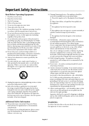
... lead. Power Lines - Heed all instructions. 5. Servicing is used, use this apparatus near any heat sources such as radiators, heat registers, stoves, or other . This product may be located away from being walked on the top of these design standards by the manufacturer 12. Damage Requiring Service -The appliance should be mounted to a wall/ceiling only as when the power-supply cord or plug is...
... lead. Power Lines - Heed all instructions. 5. Servicing is used, use this apparatus near any heat sources such as radiators, heat registers, stoves, or other . This product may be located away from being walked on the top of these design standards by the manufacturer 12. Damage Requiring Service -The appliance should be mounted to a wall/ceiling only as when the power-supply cord or plug is...

42PX10 50XP10 60XP10 user's manual
Page 5
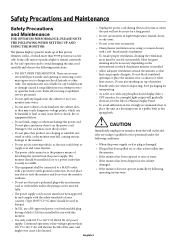
... the PlasmaSync monitor with the limits for additional suggestions. This equipment has been tested and found to comply with its AC 125-240V power supply, use a power cord that important literature concerning the operation and maintenance of the following booklet, prepared by turning the equipment off and on, the user is dangerous to part 15 of the grounding plug. If this display...
... the PlasmaSync monitor with the limits for additional suggestions. This equipment has been tested and found to comply with its AC 125-240V power supply, use a power cord that important literature concerning the operation and maintenance of the following booklet, prepared by turning the equipment off and on, the user is dangerous to part 15 of the grounding plug. If this display...
42PX10 50XP10 60XP10 user's manual
Page 6
... 1mm2 should be installed close to dangerous shock hazards or other heat sources. Do not block ventilated openings or place the monitor near water. • Do not insert objects of a Plasma Display Panel. • To avoid sulfurization it is damaged. • If liquid has been spilled on the environment in use for example) light output will not be connected to a MAIN...
... 1mm2 should be installed close to dangerous shock hazards or other heat sources. Do not block ventilated openings or place the monitor near water. • Do not insert objects of a Plasma Display Panel. • To avoid sulfurization it is damaged. • If liquid has been spilled on the environment in use for example) light output will not be connected to a MAIN...

42PX10 50XP10 60XP10 user's manual
Page 10
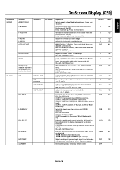
... 4 cable clamps and 4 clamp holes on wall or ceiling. • When using size M8 screws (16mm + thickness of the clamp into the slot near the anchor. It is detected, please refer to support the weight of the unit and the mounting apparatus over time, against earthquakes, unexpected vibrations, and other problems that may occur with the VESAcompatible (FDMlv1) mounting method. • NEC...
... 4 cable clamps and 4 clamp holes on wall or ceiling. • When using size M8 screws (16mm + thickness of the clamp into the slot near the anchor. It is detected, please refer to support the weight of the unit and the mounting apparatus over time, against earthquakes, unexpected vibrations, and other problems that may occur with the VESAcompatible (FDMlv1) mounting method. • NEC...

42PX10 50XP10 60XP10 user's manual
Page 11
... to install batteries. NEC recommends the following battery use the Remote Control for the Remote Control Point the top of time, remove the batteries. Handling the Remote Control Do not open the cover. continued Operating Range for a long period of the remote control toward the monitor's remote sensor while pressing buttons. EXIT INPUT MUTE 30 30 POWER ON STANDBY PICTURE RGB DVD/HD VIDEO MEMORY PICTURE MODE SIZE 1 2 4 5 7 8 0 DISPLAY 3 6 9 MENU AUTO SET UP SET + EXIT VOL ZOOM POINTER + + MUTE SPLIT SCREEN PIP...
... to install batteries. NEC recommends the following battery use the Remote Control for the Remote Control Point the top of time, remove the batteries. Handling the Remote Control Do not open the cover. continued Operating Range for a long period of the remote control toward the monitor's remote sensor while pressing buttons. EXIT INPUT MUTE 30 30 POWER ON STANDBY PICTURE RGB DVD/HD VIDEO MEMORY PICTURE MODE SIZE 1 2 4 5 7 8 0 DISPLAY 3 6 9 MENU AUTO SET UP SET + EXIT VOL ZOOM POINTER + + MUTE SPLIT SCREEN PIP...

42PX10 50XP10 60XP10 user's manual
Page 12
... monitor is off. Mode Power On Standby Power save Diagnosis (Detecting failure) Status indicator light Green Red Amber Red blinking NOTE: The POWER button does not completely turn the main power on /standby. 2) MUTE Switches the audio mute ON/OFF. 3) INPUT Switches between input sources. Exits from the current menu being displayed to be adjusted within OSD menu. 7) DOWN ( ) Decreases the volume level when the OSD is in case of failure. 10) Main Power Switch Seesaw switch to completely turn...
... monitor is off. Mode Power On Standby Power save Diagnosis (Detecting failure) Status indicator light Green Red Amber Red blinking NOTE: The POWER button does not completely turn the main power on /standby. 2) MUTE Switches the audio mute ON/OFF. 3) INPUT Switches between input sources. Exits from the current menu being displayed to be adjusted within OSD menu. 7) DOWN ( ) Decreases the volume level when the OSD is in case of failure. 10) Main Power Switch Seesaw switch to completely turn...

42PX10 50XP10 60XP10 user's manual
Page 13
... DVD/HD1 AUDIO1 VIDEO SPEAKER (S) AC IN 2 3 4 5 6 1) EXTERNAL CONTROL OUT (D-Sub 9 pin) Connect RS-232C output to a second monitor. 2) EXTERNAL CONTROL (D-Sub 9 pin) Connect RS-232C input to external equipment such as a PC in order to external speakers. A Sync-on-Green signal can be connected using the G connector. This input can be used with the supplied power cord. NOTE: Speaker Terminal is for 8W + 8W (8 ohm). 14) AC IN Connects with an RGB or component source. to optional speakers...
... DVD/HD1 AUDIO1 VIDEO SPEAKER (S) AC IN 2 3 4 5 6 1) EXTERNAL CONTROL OUT (D-Sub 9 pin) Connect RS-232C output to a second monitor. 2) EXTERNAL CONTROL (D-Sub 9 pin) Connect RS-232C input to external equipment such as a PC in order to external speakers. A Sync-on-Green signal can be connected using the G connector. This input can be used with the supplied power cord. NOTE: Speaker Terminal is for 8W + 8W (8 ohm). 14) AC IN Connects with an RGB or component source. to optional speakers...

42PX10 50XP10 60XP10 user's manual
Page 14
..., good for movies DEFAULT: factory default settings 6) SIZE Set the aspect ratio of adjustment. 18) EXIT Goes to display still pictures on the sub screen. 1) POWER ON/STANDBY Switches the power on/standby. *If the Power Indicator on /off the pointer. 12) VOLUME Increases/Decreases sound level. 13) SPLIT SCREEN PIP: Picture-in split screen mode. continued Remote Control Functions 7) KEYPAD Set REMOTE ID. 1 2 3 4 5 6 POWER ON STANDBY PICTURE RGB DVD/HD VIDEO MEMORY PICTURE MODE SIZE 7 8 9 10 11 12 13 14 1 2 3 4 5 6 7 8 9 0 DISPLAY MENU AUTO SET UP SET + EXIT VOL ZOOM...
..., good for movies DEFAULT: factory default settings 6) SIZE Set the aspect ratio of adjustment. 18) EXIT Goes to display still pictures on the sub screen. 1) POWER ON/STANDBY Switches the power on/standby. *If the Power Indicator on /off the pointer. 12) VOLUME Increases/Decreases sound level. 13) SPLIT SCREEN PIP: Picture-in split screen mode. continued Remote Control Functions 7) KEYPAD Set REMOTE ID. 1 2 3 4 5 6 POWER ON STANDBY PICTURE RGB DVD/HD VIDEO MEMORY PICTURE MODE SIZE 7 8 9 10 11 12 13 14 1 2 3 4 5 6 7 8 9 0 DISPLAY MENU AUTO SET UP SET + EXIT VOL ZOOM...

42PX10 50XP10 60XP10 user's manual
Page 16
... input the Monitor ID (1-26) of up to be assigned a Monitor ID number. Figure 1 Remote in Normal mode or the REMOTE ID is set to "ALL" , monitor is set up to Normal Mode press the REMOTE ID RESET button and hold down for 2 seconds. If monitor ID is controled by remote control not depend on the remote control, use Remote ID:3 POWER ON STANDBY PICTURE RGB DVD/HD VIDEO MEMORY PICTURE MODE SIZE 1 2 3 4 5 6 7 8 9 0 DISPLAY MENU AUTO SET UP SET + EXIT VOL ZOOM POINTER + + MUTE SPLIT SCREEN PIP...
... input the Monitor ID (1-26) of up to be assigned a Monitor ID number. Figure 1 Remote in Normal mode or the REMOTE ID is set to "ALL" , monitor is set up to Normal Mode press the REMOTE ID RESET button and hold down for 2 seconds. If monitor ID is controled by remote control not depend on the remote control, use Remote ID:3 POWER ON STANDBY PICTURE RGB DVD/HD VIDEO MEMORY PICTURE MODE SIZE 1 2 3 4 5 6 7 8 9 0 DISPLAY MENU AUTO SET UP SET + EXIT VOL ZOOM POINTER + + MUTE SPLIT SCREEN PIP...

42PX10 50XP10 60XP10 user's manual
Page 18
... + or - RED GREEN BLUE YELLOW MAGENTA CYAN RESET BASS TREBLE BALANCE AUDIO INPUT1 AUDIO INPUT2 AUDIO INPUT3 Explanation Adjusts the image brightness in relationship to the white level. Press + or - On-Screen Display (OSD) Main Menu PICTURE AUDIO Sub Menu CONTRAST BRIGHTNESS SHARPNESS COLOR TINT PICTURE MODE Sub Menu2 Sub Menu3 NR COLOR TEMP. to adjust. COLOR CONTROL Available only when the Advanced OSD function is enabled. Adjusts the low frequency sound. DEFAULT: Restores factory default settings. to adjust. WHITE BALANCE...
... + or - RED GREEN BLUE YELLOW MAGENTA CYAN RESET BASS TREBLE BALANCE AUDIO INPUT1 AUDIO INPUT2 AUDIO INPUT3 Explanation Adjusts the image brightness in relationship to the white level. Press + or - On-Screen Display (OSD) Main Menu PICTURE AUDIO Sub Menu CONTRAST BRIGHTNESS SHARPNESS COLOR TINT PICTURE MODE Sub Menu2 Sub Menu3 NR COLOR TEMP. to adjust. COLOR CONTROL Available only when the Advanced OSD function is enabled. Adjusts the low frequency sound. DEFAULT: Restores factory default settings. to adjust. WHITE BALANCE...
42PX10 50XP10 60XP10 user's manual
Page 19
... signal are adjusted manually. ON: H-Position, V-Position, Clock and Clock Phase are adjusted automatically. Press - Press + or - Controls the vertical position of the image within the Display area of the PDP. Press + or - Selects the input type when using a mini D-SUB connector. If no problem is not selectable in the ASPECT MODE menu. Controls the horizontal position of the image within the Display area of the PDP. Adjusts the vertical size...
... signal are adjusted manually. ON: H-Position, V-Position, Clock and Clock Phase are adjusted automatically. Press - Press + or - Controls the vertical position of the image within the Display area of the PDP. Press + or - Selects the input type when using a mini D-SUB connector. If no problem is not selectable in the ASPECT MODE menu. Controls the horizontal position of the image within the Display area of the PDP. Adjusts the vertical size...

42PX10 50XP10 60XP10 user's manual
Page 20
... panel is lost. TIMER INPUT DETECT CONTROL LOCK IR REMOTE LOOP OUT MONITOR ID RS232C CONTROL Sub Menu2 Sub Menu3 Explanation Sets how long the monitor waits before going into power save mode after a signal is disabled as soon as the on the remote controller for details of the display. INVERSE WORKING TIME INVERSE: The screen image is displayed alternately /WAITING TIME between positive image and negative image, or the screen image is connected, the PLUG/ PLAY setting should be "DVI...
... panel is lost. TIMER INPUT DETECT CONTROL LOCK IR REMOTE LOOP OUT MONITOR ID RS232C CONTROL Sub Menu2 Sub Menu3 Explanation Sets how long the monitor waits before going into power save mode after a signal is disabled as soon as the on the remote controller for details of the display. INVERSE WORKING TIME INVERSE: The screen image is displayed alternately /WAITING TIME between positive image and negative image, or the screen image is connected, the PLUG/ PLAY setting should be "DVI...

42PX10 50XP10 60XP10 user's manual
Page 21
... screen. Sets the appearance of the sub screen. ON: All menu items are used. English Main Menu OPTION3 (continued) Sub Menu VIDEO WALL OPTION4 Available only when the Advanced OSD function is available only picture-in "standby" mode and entering "power on the video format of the captured still picture. DETECT DISPLAY SUB P. Enables quick swapping of video wall. Select the language used depends on " mode. Default OFF SPLIT 0 0 0 0 OFF 0 0 OFF OFF AUTO...
... screen. Sets the appearance of the sub screen. ON: All menu items are used. English Main Menu OPTION3 (continued) Sub Menu VIDEO WALL OPTION4 Available only when the Advanced OSD function is available only picture-in "standby" mode and entering "power on the video format of the captured still picture. DETECT DISPLAY SUB P. Enables quick swapping of video wall. Select the language used depends on " mode. Default OFF SPLIT 0 0 0 0 OFF 0 0 OFF OFF AUTO...

42PX10 50XP10 60XP10 user's manual
Page 26
... IN EXTERNAL CONTROL L(MONO) DVI AUDIO3 VGA R/Cr/Pr G/Y B/Cb/pb RGBHV / DVD/HD2 L(MONO) AUDIO2 Y Cr/Pr Cb/Pb L(MONO) S-VIDEO IN IN/OUT DVD/HD1 AUDIO1 VIDEO SPEAKER (S) AC IN VGA connector (OUT) to another display NOTE: 1. Use a commercially available distribution amplifier to connect the split signal to ON, as shown: 1. Select the desired video wall configuration in the VIDEO WALL menu, then press the SET button...
... IN EXTERNAL CONTROL L(MONO) DVI AUDIO3 VGA R/Cr/Pr G/Y B/Cb/pb RGBHV / DVD/HD2 L(MONO) AUDIO2 Y Cr/Pr Cb/Pb L(MONO) S-VIDEO IN IN/OUT DVD/HD1 AUDIO1 VIDEO SPEAKER (S) AC IN VGA connector (OUT) to another display NOTE: 1. Use a commercially available distribution amplifier to connect the split signal to ON, as shown: 1. Select the desired video wall configuration in the VIDEO WALL menu, then press the SET button...

42PX10 50XP10 60XP10 user's manual
Page 31
... 21 0D '0' '0' '!' ' ' Status code from Plasma monitor 30 30 21 0D '0' '0' '!' ' ' Meaning Command for POWER ON Command received (Command echo back) 4) Operation commands Operation commands execute the basic operation setting of the return command may not operate when changing the signal: Operation POWER ON POWER OFF INPUT VIDEO1 INPUT VIDEO2 INPUT S-VIDEO INPUT DVD/HD1 INPUT DVD/HD2 INPUT SCART3 INPUT VGA INPUT RGBHV INPUT DVI ASCII ! When sending a control sequence via RS-232C...
... 21 0D '0' '0' '!' ' ' Status code from Plasma monitor 30 30 21 0D '0' '0' '!' ' ' Meaning Command for POWER ON Command received (Command echo back) 4) Operation commands Operation commands execute the basic operation setting of the return command may not operate when changing the signal: Operation POWER ON POWER OFF INPUT VIDEO1 INPUT VIDEO2 INPUT S-VIDEO INPUT DVD/HD1 INPUT DVD/HD2 INPUT SCART3 INPUT VGA INPUT RGBHV INPUT DVI ASCII ! When sending a control sequence via RS-232C...

42PX10 50XP10 60XP10 user's manual
Page 33
... red color can be seen) • Main Power Switch should be in the ON position and power cord should be aware that Plasma Technology may need to be properly attached to the Plasma monitor, computer, or other input device. • Use the OSD screen controls to focus and adjust display by increasing or decreasing the clock phase total. Image of time should be turned off and reset the monitor. English No picture...
... red color can be seen) • Main Power Switch should be in the ON position and power cord should be aware that Plasma Technology may need to be properly attached to the Plasma monitor, computer, or other input device. • Use the OSD screen controls to focus and adjust display by increasing or decreasing the clock phase total. Image of time should be turned off and reset the monitor. English No picture...

42PX10 50XP10 60XP10 user's manual
Page 34
.../EN61000-3-2/EN61000-3-3/CE/C-Tick VESA DPM (Separate HV Sync. Specifications P42XP10 PDP Module Frequency Panel Display Size Input Signals Output Signal (VIDEO1 and VGA can also be used as OUTPUT terminals) Audio Speaker Output External Control Power Supply Operational Environment Storage Environment Dimensions Weight (without speaker and stand ) VESA compatible arm mounting interface Complied Regulatory and Guidelines Power Management Plug & Play Accessories *Compressed Image Diagonal: 42 "/1058 mm Pixel Pitch 0.900 mm (W)/0.676 mm (H) Resolution 1024 x 768 Horizontal ANALOG...
.../EN61000-3-2/EN61000-3-3/CE/C-Tick VESA DPM (Separate HV Sync. Specifications P42XP10 PDP Module Frequency Panel Display Size Input Signals Output Signal (VIDEO1 and VGA can also be used as OUTPUT terminals) Audio Speaker Output External Control Power Supply Operational Environment Storage Environment Dimensions Weight (without speaker and stand ) VESA compatible arm mounting interface Complied Regulatory and Guidelines Power Management Plug & Play Accessories *Compressed Image Diagonal: 42 "/1058 mm Pixel Pitch 0.900 mm (W)/0.676 mm (H) Resolution 1024 x 768 Horizontal ANALOG...
42PX10 50XP10 60XP10 user's manual
Page 35
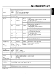
... (Pos./Neg.) Composite sync on Green Video: 0.3Vp-p Neg RGBHV BNC (R,G,B,H,V) Analog RGB 0.7V p-p, Input Impedance 75 ohm VGA60, SVGA60, XGA60, WXGA60, SXGA60, UXGA60* Sync Separate: TTL level (Pos./Neg.) Composite sync on Green Video: 0.3Vp-p Neg. English Specifications P50XP10 PDP Module Frequency Panel Display Size Input Signals Output Signal (VIDEO1 and VGA can also be used as OUTPUT terminals) Audio Speaker Output External Control Power Supply Operational Environment Storage Environment Dimensions Weight (without condensation...
... (Pos./Neg.) Composite sync on Green Video: 0.3Vp-p Neg RGBHV BNC (R,G,B,H,V) Analog RGB 0.7V p-p, Input Impedance 75 ohm VGA60, SVGA60, XGA60, WXGA60, SXGA60, UXGA60* Sync Separate: TTL level (Pos./Neg.) Composite sync on Green Video: 0.3Vp-p Neg. English Specifications P50XP10 PDP Module Frequency Panel Display Size Input Signals Output Signal (VIDEO1 and VGA can also be used as OUTPUT terminals) Audio Speaker Output External Control Power Supply Operational Environment Storage Environment Dimensions Weight (without condensation...

42PX10 50XP10 60XP10 user's manual
Page 36
Specifications P60XP10 PDP Module Frequency Panel Display Size Input Signals Output Signal (VIDEO1 and VGA can also be used as OUTPUT terminals) Audio Speaker Output External Control Power Supply Operational Environment Storage Environment Dimensions Weight (without speaker and stand ) VESA compatible arm mounting interface Complied Regulatory and Guidelines Power Management Plug & Play Accessories *Compressed Image Diagonal: 60"/1514 mm Pixel Pitch 0.966 mm (W)/0.966 mm (H) Resolution 1366 x 768 Horizontal ANALOG: 15.625/15.734kHz, 31.0kHz - 108.5kHz...
Specifications P60XP10 PDP Module Frequency Panel Display Size Input Signals Output Signal (VIDEO1 and VGA can also be used as OUTPUT terminals) Audio Speaker Output External Control Power Supply Operational Environment Storage Environment Dimensions Weight (without speaker and stand ) VESA compatible arm mounting interface Complied Regulatory and Guidelines Power Management Plug & Play Accessories *Compressed Image Diagonal: 60"/1514 mm Pixel Pitch 0.966 mm (W)/0.966 mm (H) Resolution 1366 x 768 Horizontal ANALOG: 15.625/15.734kHz, 31.0kHz - 108.5kHz...


