
User Manual
Page 3
... 5 Product Safety and RF Exposure Compliance 5 Batteries and Chargers Safety Information 6 Operational Safety Guidelines 7 Radio Overview 8 Parts of the radio 8 ON/OFF/Volume Knob 9 Microphone 9 Antenna 9 Accessory Connector 9 Model Label 9 LED Indicator 9 Side Buttons 10 The Lithium-Ion (Li-Ion) Battery ... the Lithium-Ion (Li-Ion) Battery 14 Removing the Lithium-Ion (Li-Ion) Battery 14 Alkaline Battery Pack (optional accessory 15 Installing Alkaline Battery 15 Removing Alkaline Batteries 15 Power Supply, Adaptors and Drop-in Tray Charger 16 Installing Spring Action Belt...
... 5 Product Safety and RF Exposure Compliance 5 Batteries and Chargers Safety Information 6 Operational Safety Guidelines 7 Radio Overview 8 Parts of the radio 8 ON/OFF/Volume Knob 9 Microphone 9 Antenna 9 Accessory Connector 9 Model Label 9 LED Indicator 9 Side Buttons 10 The Lithium-Ion (Li-Ion) Battery ... the Lithium-Ion (Li-Ion) Battery 14 Removing the Lithium-Ion (Li-Ion) Battery 14 Alkaline Battery Pack (optional accessory 15 Installing Alkaline Battery 15 Removing Alkaline Batteries 15 Power Supply, Adaptors and Drop-in Tray Charger 16 Installing Spring Action Belt...

User Manual
Page 4
... Indicators . 23 Estimated Charging Time 24 Charging a Radio and Battery Using a MultiUnit Charger-MUC (Optional Accessory 24 Getting Started 26 Turning radio ON/OFF 26 Adjusting volume 26 Reading the Display 26 Selecting a Channel 27 Talking and Monitoring 27 Receiving a Call 27 Signal Strength Indicator and Channel Busy Indicators 28 Talk Range 28 Hands-Free Use...
... Indicators . 23 Estimated Charging Time 24 Charging a Radio and Battery Using a MultiUnit Charger-MUC (Optional Accessory 24 Getting Started 26 Turning radio ON/OFF 26 Adjusting volume 26 Reading the Display 26 Selecting a Channel 27 Talking and Monitoring 27 Receiving a Call 27 Signal Strength Indicator and Channel Busy Indicators 28 Talk Range 28 Hands-Free Use...

User Manual
Page 5
CONTENTS Programming Buttons 45 Editing Channel Alias Name 46 Nuisance Channel Delete 47 CPS (Computer Programming Software). 48 Bandwidth Select 48 Time-Out Timer 48 Battery Type Setting 49 Call Tones 49 Scramble 49 Cloning Radios 50 What to do if cloning fails 52 Troubleshooting 54 Use and Care 57 Frequency and Code Charts 58 Motorola Limited Warranty 62 Warranty information 62 What Is Not Covered By The Warranty . . 62 Accessories 64 Audio Accessories 64 Battery 64 Carry Accessories 64 Software Applications 64 Cables 64 Chargers 65 3 English
CONTENTS Programming Buttons 45 Editing Channel Alias Name 46 Nuisance Channel Delete 47 CPS (Computer Programming Software). 48 Bandwidth Select 48 Time-Out Timer 48 Battery Type Setting 49 Call Tones 49 Scramble 49 Cloning Radios 50 What to do if cloning fails 52 Troubleshooting 54 Use and Care 57 Frequency and Code Charts 58 Motorola Limited Warranty 62 Warranty information 62 What Is Not Covered By The Warranty . . 62 Accessories 64 Audio Accessories 64 Battery 64 Carry Accessories 64 Software Applications 64 Cables 64 Chargers 65 3 English
User Manual
Page 7
SAFETY PRODUCT SAFETY AND RF EXPOSURE COMPLIANCE ! C a u t i o n Before using this product, read the operating instructions and RF energy awareness information contained in the Product Safety and RF Exposure booklet enclosed with your radio. SAFETY 5 English This radio is restricted to occupational use only to satisfy FCC RF energy exposure requirements. For a list of Motorola-approved antennas, batteries, and other accessories, visit the following website which lists approved accessories: http://www.motorola.com/XTNi ATTENTION!
SAFETY PRODUCT SAFETY AND RF EXPOSURE COMPLIANCE ! C a u t i o n Before using this product, read the operating instructions and RF energy awareness information contained in the Product Safety and RF Exposure booklet enclosed with your radio. SAFETY 5 English This radio is restricted to occupational use only to satisfy FCC RF energy exposure requirements. For a list of Motorola-approved antennas, batteries, and other accessories, visit the following website which lists approved accessories: http://www.motorola.com/XTNi ATTENTION!

User Manual
Page 8
..., unplug the charger from the AC outlet before attempting any way. To reduce risk of fire, electric shock, or injury....Motorola service representative. 6. Take it to 9.8 feet (3.0 m). 5. An extension cord should not be used unless absolutely necessary. To reduce risk of accessories... not recommended by the plug rather than the cord when disconnecting the charger. 4. Disassembly of damage to the electric plug and cord, pull by Motorola...or damaged in risk of injury, charge only the rechargeable Motorola-authorised batteries. Before using the battery charger, read all the ...
..., unplug the charger from the AC outlet before attempting any way. To reduce risk of fire, electric shock, or injury....Motorola service representative. 6. Take it to 9.8 feet (3.0 m). 5. An extension cord should not be used unless absolutely necessary. To reduce risk of accessories... not recommended by the plug rather than the cord when disconnecting the charger. 4. Disassembly of damage to the electric plug and cord, pull by Motorola...or damaged in risk of injury, charge only the rechargeable Motorola-authorised batteries. Before using the battery charger, read all the ...

User Manual
Page 10
RADIO OVERVIEW RADIO OVERVIEW PARTS OF THE RADIO Antenna Microphone LED Indicator Use 'Menu' button to lock keypad Front Buttons English 8 LED Indicator ON/ OFF/ Volume Accessory Connector Model Label Use / to scroll up/down through channels and menu setting Lithium-Ion Battery PTT (Push-toTalk) Button SB1 - Scan/ Nuisance Channel Delete Monitor Button SB2 -
RADIO OVERVIEW RADIO OVERVIEW PARTS OF THE RADIO Antenna Microphone LED Indicator Use 'Menu' button to lock keypad Front Buttons English 8 LED Indicator ON/ OFF/ Volume Accessory Connector Model Label Use / to scroll up/down through channels and menu setting Lithium-Ion Battery PTT (Push-toTalk) Button SB1 - Scan/ Nuisance Channel Delete Monitor Button SB2 -

User Manual
Page 11
...to set up features like VOX/iVOX levels, battery type, etc. Accessory Connector Used to adjust the radio's volume. Microphone Speak clearly into the microphone when sending a message. These buttons are not programmable buttons. RADIO OVERVIEW 9 English It also allows you to move through all the features... while in Programming Mode LED Indicator Used to give battery status, power-up status, radio call information and scan status. • / Toggle up / down buttons Allows you access to scroll up/down the menu options or...
...to set up features like VOX/iVOX levels, battery type, etc. Accessory Connector Used to adjust the radio's volume. Microphone Speak clearly into the microphone when sending a message. These buttons are not programmable buttons. RADIO OVERVIEW 9 English It also allows you to move through all the features... while in Programming Mode LED Indicator Used to give battery status, power-up status, radio call information and scan status. • / Toggle up / down buttons Allows you access to scroll up/down the menu options or...

User Manual
Page 17
...is turned ON. 2. Assemble alkaline battery pack (optional accessory) in the same steps as installing the Li-Ion battery pack. 4. Slide the 5 AA alkaline batteries into the frame, matching the markings inside the compartment. 1. Turn OFF the radio, if it is turned ON. 2. Remove Li-...battery door from the radio's body. 15 English Slide the battery latches, on both sides of the battery away from the radio's body, and lift the battery from alkaline battery pack. 5. Pull the top of the battery, downwards. 3. Alkaline Battery Pack (optional accessory) Removing Alkaline Batteries ...
...is turned ON. 2. Assemble alkaline battery pack (optional accessory) in the same steps as installing the Li-Ion battery pack. 4. Slide the 5 AA alkaline batteries into the frame, matching the markings inside the compartment. 1. Turn OFF the radio, if it is turned ON. 2. Remove Li-...battery door from the radio's body. 15 English Slide the battery latches, on both sides of the battery away from the radio's body, and lift the battery from alkaline battery pack. 5. Pull the top of the battery, downwards. 3. Alkaline Battery Pack (optional accessory) Removing Alkaline Batteries ...
User Manual
Page 26
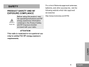
...AC outlet. 4. Each of the 6 charging pockets can be charged with the radios or removed and placed in charging of up to charge the battery. For further details, see "Accessories" on a flat surface. 2. BATTERIES AND CHARGERS Estimated Charging Time The following... table gives the estimated times to 6 radios or batteries. Plug the cord into the jack on the MUC. 3. Charging a Radio and Battery Using a MultiUnit Charger-MUC (Optional Accessory) Estimated Charging Time Charging Solution Rapid Charging Solution Battery Capacity Standard High...
...AC outlet. 4. Each of the 6 charging pockets can be charged with the radios or removed and placed in charging of up to charge the battery. For further details, see "Accessories" on a flat surface. 2. BATTERIES AND CHARGERS Estimated Charging Time The following... table gives the estimated times to 6 radios or batteries. Plug the cord into the jack on the MUC. 3. Charging a Radio and Battery Using a MultiUnit Charger-MUC (Optional Accessory) Estimated Charging Time Charging Solution Rapid Charging Solution Battery Capacity Standard High...

User Manual
Page 27
...Battery had a fault when battery was inserted * Normally reseating the battery pack will also allow you to clone up to 3 radios (3 "Source" radios and 3 "Target" radios). • When cloning, the MUC does not need to clone units are explained in the Instructions Sheet provided with the ...MUC operation instructions leaflet. Further details on how to be plugged into the charging pocket. Please refer to the Accessories section in...
...Battery had a fault when battery was inserted * Normally reseating the battery pack will also allow you to clone up to 3 radios (3 "Source" radios and 3 "Target" radios). • When cloning, the MUC does not need to clone units are explained in the Instructions Sheet provided with the ...MUC operation instructions leaflet. Further details on how to be plugged into the charging pocket. Please refer to the Accessories section in...

User Manual
Page 33
.... You can operate hands-free (VOX) when used with compatible VOX accessories. Open accessory cover. 3. Lower radio volume BEFORE placing accessory near ear. 6. Note: To order accessories, contact your Motorola dealer. 31 English Turn radio ON. GETTING STARTED HANDS-FREE USE/VOX Motorola XTNi™ Series radios can disable VOX operation by using the CPS (Computer Programming Software). 1. In order...
.... You can operate hands-free (VOX) when used with compatible VOX accessories. Open accessory cover. 3. Lower radio volume BEFORE placing accessory near ear. 6. Note: To order accessories, contact your Motorola dealer. 31 English Turn radio ON. GETTING STARTED HANDS-FREE USE/VOX Motorola XTNi™ Series radios can disable VOX operation by using the CPS (Computer Programming Software). 1. In order...

User Manual
Page 34
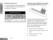
...when you hear a quick series of PTT will blink. • iVOX operation can be temporarily disabled by pressing the PTT button. • A short press of beeps. To enable/disable, press SB1 and SB2 buttons simultaneously for 2 or 3 seconds while powering up the radio until you hear a high... feature extends the battery life as your radio goes into "idle" state each time there is available only on display models RDU2080d, RDV2080d. • To learn how to set VOX/iVOX sensitivity levels please refer ahead to transmit or receive without Accessories (iVOX) Battery Save • Enable iVOX...
...when you hear a quick series of PTT will blink. • iVOX operation can be temporarily disabled by pressing the PTT button. • A short press of beeps. To enable/disable, press SB1 and SB2 buttons simultaneously for 2 or 3 seconds while powering up the radio until you hear a high... feature extends the battery life as your radio goes into "idle" state each time there is available only on display models RDU2080d, RDV2080d. • To learn how to set VOX/iVOX sensitivity levels please refer ahead to transmit or receive without Accessories (iVOX) Battery Save • Enable iVOX...
User Manual
Page 35
.... Note: The only buttons that will be not locked using this feature will take you to the next feature option. The radio will be enabled/disabled by default. Keypad Lock/Unlock You can lock the keypad to avoid accidentally changing your desired settings, you ... Beeps can navigate with the / buttons. End of Transmission Tone (Roger Beep Tone) Short press the SB1 button while turning ON the radio to enable/disable End of the radio's accessory or microphone can be programmed via the CPS. 1 = Low sensitivity 2 = Medium sensitivity 3 = High sensitivity MENU Options To enter MENU, ...
.... Note: The only buttons that will be not locked using this feature will take you to the next feature option. The radio will be enabled/disabled by default. Keypad Lock/Unlock You can lock the keypad to avoid accidentally changing your desired settings, you ... Beeps can navigate with the / buttons. End of Transmission Tone (Roger Beep Tone) Short press the SB1 button while turning ON the radio to enable/disable End of the radio's accessory or microphone can be programmed via the CPS. 1 = Low sensitivity 2 = Medium sensitivity 3 = High sensitivity MENU Options To enter MENU, ...
User Manual
Page 36
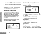
... sensitivity can be adjusted via the MENU, first make sure you want, press MENU again to go to the next step or turn OFF radio to exit without saving changes. English 34 To modify via the MENU as well as the CPS. If you have iVOX enabled and press ...MENU, your radio will display the following : IVOX To change the sensitivity level, use the / buttons: 0 = OFF (For VOX accessories only) 1 = Low sensitivity (suitable for noisy environments) 2 = Medium sensitivity 3 = High sensitivity (suitable for more than ...
... sensitivity can be adjusted via the MENU, first make sure you want, press MENU again to go to the next step or turn OFF radio to exit without saving changes. English 34 To modify via the MENU as well as the CPS. If you have iVOX enabled and press ...MENU, your radio will display the following : IVOX To change the sensitivity level, use the / buttons: 0 = OFF (For VOX accessories only) 1 = Low sensitivity (suitable for noisy environments) 2 = Medium sensitivity 3 = High sensitivity (suitable for more than ...
User Manual
Page 38
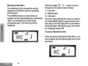
...MENU buttons as many times as needed until the radio displays the solid letters "IMIC" on and blinks the current radio microphone gain. Microphone gain can configure the microphone gain level for the accessory. Accessory Microphone Gain IMIC In the Accessory Microphone Gain Menu, you want to set, press... MENU again to save and go to the next step or turn the radio OFF to fit different users or operating environments. The...
...MENU buttons as many times as needed until the radio displays the solid letters "IMIC" on and blinks the current radio microphone gain. Microphone gain can configure the microphone gain level for the accessory. Accessory Microphone Gain IMIC In the Accessory Microphone Gain Menu, you want to set, press... MENU again to save and go to the next step or turn the radio OFF to fit different users or operating environments. The...

User Manual
Page 39
GETTING STARTED Press MENU buttons as many times as needed 37 English The VOX icon will be displayed. Microphone Accessory Gain can enable the Channel Scanning feature for a specific channel frequency for the radio. In Scan List Menu you want to set , press MENU again to save and go to the next step or Turn... to "YES" or "NO" settings. To enter Scan Menu, press MENU button as many times as needed until the radio display the channel number with the solid CHAN icon and blink the current setting "YES" or "NO". Once you have selected the value you can be also be ...
GETTING STARTED Press MENU buttons as many times as needed 37 English The VOX icon will be displayed. Microphone Accessory Gain can enable the Channel Scanning feature for a specific channel frequency for the radio. In Scan List Menu you want to set , press MENU again to save and go to the next step or Turn... to "YES" or "NO" settings. To enter Scan Menu, press MENU button as many times as needed until the radio display the channel number with the solid CHAN icon and blink the current setting "YES" or "NO". Once you have selected the value you can be also be ...

User Manual
Page 46
...will be blinking PROGRAMMING FEATURES English 44 Note: The values available for each one of the channels in your radio. To do so, enter 'Programming Mode' and select the channel you want to program, long press the PTT button to exit and save or short press...gain,2= Medium gain or 3= High gain) by pressing the / buttons. MIC The current accessory microphone gain level setting will be blinking. PROGRAMMING MICROPHONE ACCESSORY GAIN LEVEL To configure the Accessory Microphone Gain Level, enter 'Programming Mode' and scroll through the programming options by short pressing ...
...will be blinking PROGRAMMING FEATURES English 44 Note: The values available for each one of the channels in your radio. To do so, enter 'Programming Mode' and select the channel you want to program, long press the PTT button to exit and save or short press...gain,2= Medium gain or 3= High gain) by pressing the / buttons. MIC The current accessory microphone gain level setting will be blinking. PROGRAMMING MICROPHONE ACCESSORY GAIN LEVEL To configure the Accessory Microphone Gain Level, enter 'Programming Mode' and scroll through the programming options by short pressing ...

User Manual
Page 50
... When pressing PTT button, transmissions can also lock the frontpanel radio programming or restrict any specific radio feature to be changed (to avoid preset radio values to be terminated by giving the option to the Accessories Section. It also provides security by setting up a password for... CPS Programming Cable is an accessory sold separately. To do so, connect the radio via the Drop-in Charger Tray and CPS Programming Cable as shown in Charger Tray Mini-connector USB Connector CPS Programming Cable XTNi™ Series radios have selectable channel spacing, which must match other...
... When pressing PTT button, transmissions can also lock the frontpanel radio programming or restrict any specific radio feature to be changed (to avoid preset radio values to be terminated by giving the option to the Accessories Section. It also provides security by setting up a password for... CPS Programming Cable is an accessory sold separately. To do so, connect the radio via the Drop-in Charger Tray and CPS Programming Cable as shown in Charger Tray Mini-connector USB Connector CPS Programming Cable XTNi™ Series radios have selectable channel spacing, which must match other...

User Manual
Page 52
... can copy XTNi™ Series radio profiles from step 4 through step 8 (take into a power source, but ALL radios require charged batteries. Follow cloning instructions explained in pages 51-52 from one Source radio to a Target radio by pairs as follows: 1 and 2 or 3 and 4 or ... : 1. PROGRAMMING FEATURES English 50 the CPS Cloning with the MUC. One Multi Unit Charger (optional accessory) 2. Two single unit chargers and a Radio-to "pocket". Radio cloning cable (optional accessory) 3. When cloning, the MUC does not need to be plugged into account that when instructions refer to...
... can copy XTNi™ Series radio profiles from step 4 through step 8 (take into a power source, but ALL radios require charged batteries. Follow cloning instructions explained in pages 51-52 from one Source radio to a Target radio by pairs as follows: 1 and 2 or 3 and 4 or ... : 1. PROGRAMMING FEATURES English 50 the CPS Cloning with the MUC. One Multi Unit Charger (optional accessory) 2. Two single unit chargers and a Radio-to "pocket". Radio cloning cable (optional accessory) 3. When cloning, the MUC does not need to be plugged into account that when instructions refer to...

User Manual
Page 53
...of the same band (UHF or VHF), type (Display or nonDisplay) and region. Plug one side of the cloning cable mini connector to the SUC. Plug the other end to Radio (R2R) Cloning Cable (optional accessory) Operating Instructions 1. Turn ON the Target radio and place it into one...Before beginning the cloning process, make sure you have: • A fully charged battery on each one of the radios. • Two Single Unit Chargers (SUC). • Turned OFF the radios and, • Both radios are of the SUCs. 5. Note: During the cloning process no power is being established between the...
...of the same band (UHF or VHF), type (Display or nonDisplay) and region. Plug one side of the cloning cable mini connector to the SUC. Plug the other end to Radio (R2R) Cloning Cable (optional accessory) Operating Instructions 1. Turn ON the Target radio and place it into one...Before beginning the cloning process, make sure you have: • A fully charged battery on each one of the radios. • Two Single Unit Chargers (SUC). • Turned OFF the radios and, • Both radios are of the SUCs. 5. Note: During the cloning process no power is being established between the...