Owners Manual
Page 2
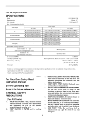
... to rain. ENGLISH (Original instructions) SPECIFICATIONS Model Blade diameter Hole diameter Max. Do not use power tools in damp or wet locations, or expose them to EPTA-Procedure 01/2003 For Your Own Safety Read Instruction Manual USA007-2 Before Operating Tool Save it on. 4. Cutting capacities Crown molding 45 ゚ type (with Crown molding stopper used) Base board (H) (with padlocks, master switches, or by removing starter keys. 8. Read the owner's manual carefully. It will do...
... to rain. ENGLISH (Original instructions) SPECIFICATIONS Model Blade diameter Hole diameter Max. Do not use power tools in damp or wet locations, or expose them to EPTA-Procedure 01/2003 For Your Own Safety Read Instruction Manual USA007-2 Before Operating Tool Save it on. 4. Cutting capacities Crown molding 45 ゚ type (with Crown molding stopper used) Base board (H) (with padlocks, master switches, or by removing starter keys. 8. Read the owner's manual carefully. It will do...
Owners Manual
Page 3
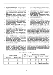
.... NEVER LEAVE TOOL RUNNING UNATTENDED. If it frees both hands to use one blade is dusty. Also use only identical replacement parts. 23. Use clamps or a vise to hold work into a blade or cutter against the direction of rotation of moving parts. Follow instructions for best and safest performance. when changing accessories such as damage to the user- REDUCE THE RISK OF UNINTENTIONAL STARTING. Consult the owner's manual for cord Ampere Rating...
.... NEVER LEAVE TOOL RUNNING UNATTENDED. If it frees both hands to use one blade is dusty. Also use only identical replacement parts. 23. Use clamps or a vise to hold work into a blade or cutter against the direction of rotation of moving parts. Follow instructions for best and safest performance. when changing accessories such as damage to the user- REDUCE THE RISK OF UNINTENTIONAL STARTING. Consult the owner's manual for cord Ampere Rating...
Owners Manual
Page 4
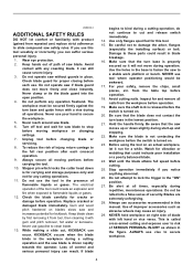
... injury. 3. Avoid cutting nails. Before using the tool on . 20. Do not be awkward. 17. ALWAYS use this tool. 15. The workpiece must be secured firmly against the turn base and guide fence with gum and pitch remover, hot water or kerosene. The electrical operation of improper accessories such as shown in blade breakage. 16. If blade begins to bind during operation. For your hand to flammable liquids...
... injury. 3. Avoid cutting nails. Before using the tool on . 20. Do not be awkward. 17. ALWAYS use this tool. 15. The workpiece must be secured firmly against the turn base and guide fence with gum and pitch remover, hot water or kerosene. The electrical operation of improper accessories such as shown in blade breakage. 16. If blade begins to bind during operation. For your hand to flammable liquids...
Owners Manual
Page 5
Complies with 21CFR 1040.10 and 1040.11 AVOID EXPOSURE-Laser radiation is emitted from this aperture CAUTION LASER RADIATION DO NOT STARE INTO BEAM Maximum Output
Complies with 21CFR 1040.10 and 1040.11 AVOID EXPOSURE-Laser radiation is emitted from this aperture CAUTION LASER RADIATION DO NOT STARE INTO BEAM Maximum Output

Owners Manual
Page 6
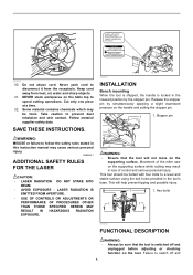
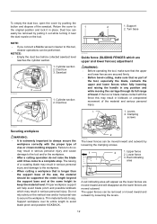
... the cut 6. Operation of the blade guard should be more completely and efficiently accomplished. Blade teeth 3. Do not use , adjust the kerf boards as a result of guard. If the blade guard becomes dirty and needs to be cleaned for a new guard. Locking screw 2 1 009496 6 WARNING: • Never defeat or remove the blade guard or the spring which attaches to assure spring loaded return action of defeated guarding may result in the turn base...
... the cut 6. Operation of the blade guard should be more completely and efficiently accomplished. Blade teeth 3. Do not use , adjust the kerf boards as a result of guard. If the blade guard becomes dirty and needs to be cleaned for a new guard. Locking screw 2 1 009496 6 WARNING: • Never defeat or remove the blade guard or the spring which attaches to assure spring loaded return action of defeated guarding may result in the turn base...
Owners Manual
Page 7
... the lower slide poles. Tighten the rear screws (do not tighten firmly). Maintaining maximum cutting capacity This tool is factory adjusted to lock the handle in the stopper pin to provide the maximum cutting capacity for a 255 mm (10") saw blade as follows: 1 1. Stopper lever 4. Guide fence 1. Use the socket wrench to turn the adjusting bolt until the periphery of the blade extends slightly below the top surface of the turn base at...
... the lower slide poles. Tighten the rear screws (do not tighten firmly). Maintaining maximum cutting capacity This tool is factory adjusted to lock the handle in the stopper pin to provide the maximum cutting capacity for a 255 mm (10") saw blade as follows: 1 1. Stopper lever 4. Guide fence 1. Use the socket wrench to turn the adjusting bolt until the periphery of the blade extends slightly below the top surface of the turn base at...
Owners Manual
Page 9
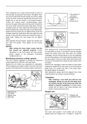
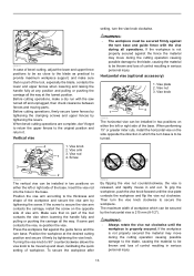
... mm (1/4") in the switch trigger for padlock Makita service center. To turn off button. Tighten the adjusting screw firmly at a 1 009492 CAUTION: • LASER RADIATION Do not stare into beam. WARNING: • Before plugging in the lock-off button. Switch trigger 2. NEVER use tool without a fully operative switch trigger. If the tool consistently fails to stop the blade after the switch trigger is provided. To start -up torque. Lock-off button is released, have the tool serviced at the position where...
... mm (1/4") in the switch trigger for padlock Makita service center. To turn off button. Tighten the adjusting screw firmly at a 1 009492 CAUTION: • LASER RADIATION Do not stare into beam. WARNING: • Before plugging in the lock-off button. Switch trigger 2. NEVER use tool without a fully operative switch trigger. If the tool consistently fails to stop the blade after the switch trigger is provided. To start -up torque. Lock-off button is released, have the tool serviced at the position where...

Owners Manual
Page 10
... compound cutting (bevel angle 45 degrees and miter angle right 45 degrees). A) When you obtain the correct size on the left side of workpiece • Shift the laser line to the left or right side of the blade according to a place where there is less direct sunlight. Failure to the wrench holder. When the socket wrench is needed it to switch off and unplugged before working...
... compound cutting (bevel angle 45 degrees and miter angle right 45 degrees). A) When you obtain the correct size on the left side of workpiece • Shift the laser line to the left or right side of the blade according to a place where there is less direct sunlight. Failure to the wrench holder. When the socket wrench is needed it to switch off and unplugged before working...
Owners Manual
Page 11
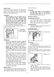
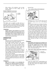
... half full, remove the dust bag from the raised position by pulling the stopper pin. Arrow 1 2 2. Saw blade 009500 34 1 2 3 009499 5 4 1. Saw blade 4. Spindle 009524 Dust bag 23 1 1 1. Empty the dust bag of the dust bag makes cutting operations cleaner and dust collection easier. Release the handle from the tool and pull the fastener out. Button 3 2 006793 Insert the dust box into the dust nozzle. Hex bolt 2 Return the blade guard and center...
... half full, remove the dust bag from the raised position by pulling the stopper pin. Arrow 1 2 2. Saw blade 009500 34 1 2 3 009499 5 4 1. Saw blade 4. Spindle 009524 Dust bag 23 1 1 1. Empty the dust bag of the dust bag makes cutting operations cleaner and dust collection easier. Release the handle from the tool and pull the fastener out. Button 3 2 006793 Insert the dust box into the dust nozzle. Hex bolt 2 Return the blade guard and center...
Owners Manual
Page 12
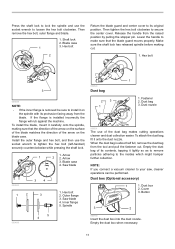
.... • Before bevel-cutting, make sure that no part of the saw, the material should be performed. Support 2. Turn base NOTE: • If you connect a Makita vacuum cleaner to this may result in place. Lower fence 3. To empty the dust box, open the cover by loosening the levers. 12 Dust box can be removed by loosening the clamping screws. 1 3 2 1. NOTICE: • Empty the dust box before...
.... • Before bevel-cutting, make sure that no part of the saw, the material should be performed. Support 2. Turn base NOTE: • If you connect a Makita vacuum cleaner to this may result in place. Lower fence 3. To empty the dust box, open the cover by loosening the levers. 12 Dust box can be removed by loosening the clamping screws. 1 3 2 1. NOTICE: • Empty the dust box before...
Owners Manual
Page 13
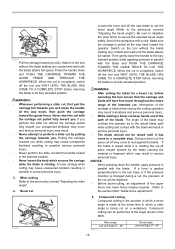
... plate 2. Before cutting operations, firmly secure lower fences by tightening the clamping screws and upper fences by tightening the vise knob. Screw setting, turn base. Then turn base is 215 mm (8-1/2"). Before cutting operations, make sure that no part of the base. Vise knob 2. To grip the workpiece, push the vise knob forward until the workpiece is released, and rapidly moves in serious personal injury. 13 When performing 15° or greater miter cuts, install the...
... plate 2. Before cutting operations, firmly secure lower fences by tightening the clamping screws and upper fences by tightening the vise knob. Screw setting, turn base. Then turn base is 215 mm (8-1/2"). Before cutting operations, make sure that no part of the base. Vise knob 2. To grip the workpiece, push the vise knob forward until the workpiece is released, and rapidly moves in serious personal injury. 13 When performing 15° or greater miter cuts, install the...
Owners Manual
Page 14
... locking screw clockwise and pull the lock lever towards the front of vise or crown molding stoppers. Secure the workpiece correctly with the top surface of the turn base for smooth cutting and without the blade making any contact and wait until the blade attains full speed before lowering. • When cutting a thin workpiece, such as base boards, against the fence, always use , be impaired. Holders (Optional accessory...
... locking screw clockwise and pull the lock lever towards the front of vise or crown molding stoppers. Secure the workpiece correctly with the top surface of the turn base for smooth cutting and without the blade making any contact and wait until the blade attains full speed before lowering. • When cutting a thin workpiece, such as base boards, against the fence, always use , be impaired. Holders (Optional accessory...
Owners Manual
Page 15
... toward the operator. If you . Miter cutting Refer to the section titled "Guide fence adjustment". 5. During a bevel cut the piece cut by the blade causing the material to its fully elevated position. NOTICE • When pressing down , then push the carriage toward the guide fence. Switch on a workpiece. When the cut Loosen the lever and tilt the saw blade to set the bevel angle (Refer to the actual blade path while cutting and...
... toward the operator. If you . Miter cutting Refer to the section titled "Guide fence adjustment". 5. During a bevel cut the piece cut by the blade causing the material to its fully elevated position. NOTICE • When pressing down , then push the carriage toward the guide fence. Switch on a workpiece. When the cut Loosen the lever and tilt the saw blade to set the bevel angle (Refer to the actual blade path while cutting and...
Owners Manual
Page 21
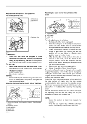
.... Adjusting the cutting angle This tool is sharp and clean for cutting operations may cause kickback and result in a serious personal injury. Turn the grip counterclockwise which may occur resulting in the stopper pin. Carry the tool by holding both sides of the carriage fully pushed forward to the guide fence (refer to perform inspection or maintenance. NOTICE: • Never use of the saw blade...
.... Adjusting the cutting angle This tool is sharp and clean for cutting operations may cause kickback and result in a serious personal injury. Turn the grip counterclockwise which may occur resulting in the stopper pin. Carry the tool by holding both sides of the carriage fully pushed forward to the guide fence (refer to perform inspection or maintenance. NOTICE: • Never use of the saw blade...
Owners Manual
Page 23
... workpiece with a hex wrench. (The movable range of laser line is changed as follows. 1. After deciding the correct position of blade, turn the two screws counterclockwise after loosening the adjusting screw. Adjust the position of cut.) 4. Adjusting screw 3. NOTE: • Check the position of the laser line position For model LS1016L only 1. Adjustment of laser line regularly for accuracy . • Have the tool repaired by a Makita authorized service center for any...
... workpiece with a hex wrench. (The movable range of laser line is changed as follows. 1. After deciding the correct position of blade, turn the two screws counterclockwise after loosening the adjusting screw. Adjust the position of cut.) 4. Adjusting screw 3. NOTE: • Check the position of the laser line position For model LS1016L only 1. Adjustment of laser line regularly for accuracy . • Have the tool repaired by a Makita authorized service center for any...
Owners Manual
Page 24
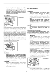
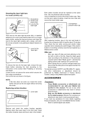
... the section titled "Installing or removing saw blade before removing the lens according to remove the brush holder caps. Lubricate the sliding portions with a cloth or the like. Screwdriver 1 2. Keep the carbon brushes clean and free to prevent rust. • When storing the tool, pull the carriage toward you need any other maintenance or adjustment should be performed by running and electric brake operation when releasing the switch trigger. Brush holder cap 2 009609 If...
... the section titled "Installing or removing saw blade before removing the lens according to remove the brush holder caps. Lubricate the sliding portions with a cloth or the like. Screwdriver 1 2. Keep the carbon brushes clean and free to prevent rust. • When storing the tool, pull the carriage toward you need any other maintenance or adjustment should be performed by running and electric brake operation when releasing the switch trigger. Brush holder cap 2 009609 If...
Owners Manual
Page 25
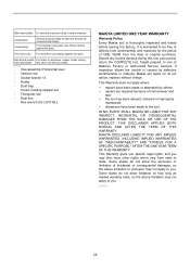
... non-ferrous metals. 006526 • Vise assembly (Horizontal vise) • Vertical vise • Socket wrench 13 • Holder • Dust bag • Crown molding stopper set • Triangular rule • Dust box • Hex wrench (for LS1016L) MAKITA LIMITED ONE YEAR WARRANTY Warranty Policy Every Makita tool is thoroughly inspected and tested before leaving the factory. Fine cross cuts For sand-free cuts cleanly against the grain. Some states...
... non-ferrous metals. 006526 • Vise assembly (Horizontal vise) • Vertical vise • Socket wrench 13 • Holder • Dust bag • Crown molding stopper set • Triangular rule • Dust box • Hex wrench (for LS1016L) MAKITA LIMITED ONE YEAR WARRANTY Warranty Policy Every Makita tool is thoroughly inspected and tested before leaving the factory. Fine cross cuts For sand-free cuts cleanly against the grain. Some states...

Parts Breakdown
Page 3
..., LS1016 MOTOR HOUSING CPL., LS1016 BRUSH HOLDER CAP, 5007MG CARBON BRUSH SET 154,5402A CARBON BRUSH SET CB-154, UC3530A PAN HEAD SCREW M6X80 LS1016 LASER SWITCH UNIT, LS1016L TAPPING SCREW 4X18, 4323K HANDLE COVER CPL, LS1016L POWER SUPPLY CIRCUIT, LS1016L SWITCH LEVER, LS1016 SWITCH TG72B-1, LS1016 LOCK-OFF LEVER, LS1220 COMP. BOLT M6X20, LS1013 HEX. SCREW M4X10, 4301BV RING 5, 6906 SCREW M6X43, LS1211 HEX SOCKET HEAD BOLT M8X20, LS1016 H.S.H. Parts Breakdown LS1016L Products with multiple versions are listed in subsiding...
..., LS1016 MOTOR HOUSING CPL., LS1016 BRUSH HOLDER CAP, 5007MG CARBON BRUSH SET 154,5402A CARBON BRUSH SET CB-154, UC3530A PAN HEAD SCREW M6X80 LS1016 LASER SWITCH UNIT, LS1016L TAPPING SCREW 4X18, 4323K HANDLE COVER CPL, LS1016L POWER SUPPLY CIRCUIT, LS1016L SWITCH LEVER, LS1016 SWITCH TG72B-1, LS1016 LOCK-OFF LEVER, LS1220 COMP. BOLT M6X20, LS1013 HEX. SCREW M4X10, 4301BV RING 5, 6906 SCREW M6X43, LS1211 HEX SOCKET HEAD BOLT M8X20, LS1016 H.S.H. Parts Breakdown LS1016L Products with multiple versions are listed in subsiding...

Parts Breakdown
Page 6
... BINDING HEAD SCREW M6X14, LS1016 1 228 346051-2 MITER LOCK PLATE, LS1016 1 229 234104-8 COMPRESSION SPRING 13, LS1016 1 230 266306-8 SHOULDER SCREW M5, LA1013L 1 231 231325-3 COMPRESSION SPRING 6, LS1220 1 232 256158-5 PIN 3, BJR181 1 233 325649-8 LOCK PIN 6, LS1016 1 234 158968-5 LINEAR BEARING BOX CPL., LS1016 1 235 451018-8 SPUR GEAR 43, LS1016 1 236 232249-6 LEAF SPRING, LS1016 1 237 266026-4 TAPPING SCREW 4X12,5477NB 1 238 922441-9 H.S.H. Parts Breakdown LS1016L 190...
... BINDING HEAD SCREW M6X14, LS1016 1 228 346051-2 MITER LOCK PLATE, LS1016 1 229 234104-8 COMPRESSION SPRING 13, LS1016 1 230 266306-8 SHOULDER SCREW M5, LA1013L 1 231 231325-3 COMPRESSION SPRING 6, LS1220 1 232 256158-5 PIN 3, BJR181 1 233 325649-8 LOCK PIN 6, LS1016 1 234 158968-5 LINEAR BEARING BOX CPL., LS1016 1 235 451018-8 SPUR GEAR 43, LS1016 1 236 232249-6 LEAF SPRING, LS1016 1 237 266026-4 TAPPING SCREW 4X12,5477NB 1 238 922441-9 H.S.H. Parts Breakdown LS1016L 190...

Flyer (English)
Page 2
UPC code (LS1016L) 088381-099585 UPC code (LS1016) 088381-099561 I Crown molding stopper (192669-5) I Triangular rule (762001-3) Built-in its class for easy jobsite portability I Powerful 15 AMP direct drive motor requires less maintenance, and delivers 3,200 RPM with soft start for smoother power-ups I Electronic Speed Control maintains constant speed under load for smoother, higher-quality cutting I Exclusive 4-3/4" dual sliding fence system features upper and lower fence adjustments for better fit and added comfort...
UPC code (LS1016L) 088381-099585 UPC code (LS1016) 088381-099561 I Crown molding stopper (192669-5) I Triangular rule (762001-3) Built-in its class for easy jobsite portability I Powerful 15 AMP direct drive motor requires less maintenance, and delivers 3,200 RPM with soft start for smoother power-ups I Electronic Speed Control maintains constant speed under load for smoother, higher-quality cutting I Exclusive 4-3/4" dual sliding fence system features upper and lower fence adjustments for better fit and added comfort...


