Owners Manual
Page 4
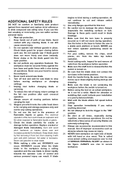
...Always secure all times, especially during all nails from the workpiece before carrying the tool. 10. Gum and wood pitch hardened on blades slows saw blade to secure the workpiece. 5. KICKBACK occurs when the blade binds in the workpiece during a cutting operation, do not continue to cut... be awkward. 17. While making a slide cut and release switch immediately. 14. It can result. Unplug tool before operation. 18. Loss of saw blade. 6. This is turned on . 20. Wear eye protection. 2. Make sure the blade is not contacting the workpiece before cutting. 25. Blades...
...Always secure all times, especially during all nails from the workpiece before carrying the tool. 10. Gum and wood pitch hardened on blades slows saw blade to secure the workpiece. 5. KICKBACK occurs when the blade binds in the workpiece during a cutting operation, do not continue to cut... be awkward. 17. While making a slide cut and release switch immediately. 14. It can result. Unplug tool before operation. 18. Loss of saw blade. 6. This is turned on . 20. Wear eye protection. 2. Make sure the blade is not contacting the workpiece before cutting. 25. Blades...
Owners Manual
Page 5
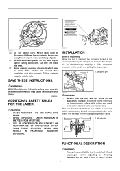
Complies with 21CFR 1040.10 and 1040.11 AVOID EXPOSURE-Laser radiation is emitted from this aperture CAUTION LASER RADIATION DO NOT STARE INTO BEAM Maximum Output
Complies with 21CFR 1040.10 and 1040.11 AVOID EXPOSURE-Laser radiation is emitted from this aperture CAUTION LASER RADIATION DO NOT STARE INTO BEAM Maximum Output

Owners Manual
Page 6
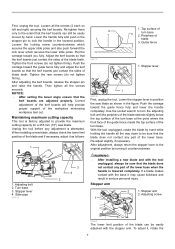
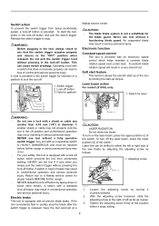
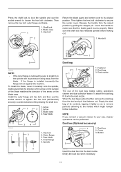
...the handle, the blade guard rises automatically. An exposed blade as follows: 1. If the see-through age or UV light exposure, contact a Makita service center for proper operation follow the steps below: With the tool switched off and unplugged, use solvents or any petroleum-based cleaners on the... blade guard becomes dirty, or sawdust adheres to minimize tearing on the plastic guard because this may result in such a way that the saw and clean the guard carefully with a damaged, faulty or removed guard may result in serious personal injury. Straight cut 5 6 001538 This...
...the handle, the blade guard rises automatically. An exposed blade as follows: 1. If the see-through age or UV light exposure, contact a Makita service center for proper operation follow the steps below: With the tool switched off and unplugged, use solvents or any petroleum-based cleaners on the... blade guard becomes dirty, or sawdust adheres to minimize tearing on the plastic guard because this may result in such a way that the saw and clean the guard carefully with a damaged, faulty or removed guard may result in serious personal injury. Straight cut 5 6 001538 This...
Owners Manual
Page 7
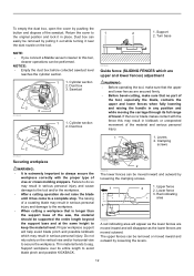
... lower base. Guide fence 1. After adjustment, always return the stopper lever to provide the maximum cutting capacity for a 255 mm (10") saw blade as follows: 1 1. Loosen the locking screw counterclockwise which secures the upper slide poles and also push forward the lock lever which secures... installing a new blade and with the stopper arm. Tighten the front screws (do not tighten firmly). Lower the stopper lever to position the saw blade. Loosen all the screws securely. Unplug the tool before any part of the turn base 2. Stopper lever 1 009736 First, unplug the tool...
... lower base. Guide fence 1. After adjustment, always return the stopper lever to provide the maximum cutting capacity for a 255 mm (10") saw blade as follows: 1 1. Loosen the locking screw counterclockwise which secures the upper slide poles and also push forward the lock lever which secures... installing a new blade and with the stopper arm. Tighten the front screws (do not tighten firmly). Lower the stopper lever to position the saw blade. Loosen all the screws securely. Unplug the tool before any part of the turn base 2. Stopper lever 1 009736 First, unplug the tool...

Owners Manual
Page 8
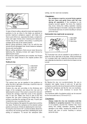
...; When changing bevel angles, be sure to position the kerf boards appropriately as explained in the figure fully while supporting the weight of the saw head so as to release the pressure on the bevel scale. Slide lock adjustment 1. Latch lever 1. With the releasing button being pressed, ...Lock lever 1 2. Locking screw 1 009489 2 1 009496 To lock the lower slide pole, pull the lock lever towards the front of the saw, the saw blade can be locked at the right and left slightly after loosening the lever and press the releasing button. Lock lever 2. When the latch lever...
...; When changing bevel angles, be sure to position the kerf boards appropriately as explained in the figure fully while supporting the weight of the saw head so as to release the pressure on the bevel scale. Slide lock adjustment 1. Latch lever 1. With the releasing button being pressed, ...Lock lever 1 2. Locking screw 1 009489 2 1 009496 To lock the lower slide pole, pull the lock lever towards the front of the saw, the saw blade can be locked at the right and left slightly after loosening the lever and press the releasing button. Lock lever 2. When the latch lever...
Owners Manual
Page 9
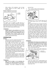
... lead to stop the blade after the switch trigger is equipped with a lock-off the laser beam, press the lower position (0) of the saw blade by taping down or some other means. Electronic function Constant speed control • The tool is provided. A smaller shank or cable may...smooth start the tool, press in the lock-off button by adjusting the adjusting screw as it counterclockwise. 2. Laser beam action For model LS1016L only 1. Switch for padlock Makita service center. Return tool to the "OFF" position when released. A switch with a shank or cable any smaller than 6.35 mm ...
... lead to stop the blade after the switch trigger is equipped with a lock-off the laser beam, press the lower position (0) of the saw blade by taping down or some other means. Electronic function Constant speed control • The tool is provided. A smaller shank or cable may...smooth start the tool, press in the lock-off button by adjusting the adjusting screw as it counterclockwise. 2. Laser beam action For model LS1016L only 1. Switch for padlock Makita service center. Return tool to the "OFF" position when released. A switch with a shank or cable any smaller than 6.35 mm ...

Owners Manual
Page 10
...Accidental start up of guide fence in compound cutting (bevel angle 45 degrees and miter angle right 45 degrees). Wrench holder 2. Installing or removing saw blade WARNING: • Always be sure that the tool is switched off and unplugged before working on the left side of workpiece • ... 3. Blade guard 4 009497 10 Stopper pin 009483 To remove the blade, use the wrench may result in serious personal injury. • Use only the Makita socket wrench provided to install or remove the blade.Failure to use the socket wrench to loosen the hex bolt holding the center cover by...
...Accidental start up of guide fence in compound cutting (bevel angle 45 degrees and miter angle right 45 degrees). Wrench holder 2. Installing or removing saw blade WARNING: • Always be sure that the tool is switched off and unplugged before working on the left side of workpiece • ... 3. Blade guard 4 009497 10 Stopper pin 009483 To remove the blade, use the wrench may result in serious personal injury. • Use only the Makita socket wrench provided to install or remove the blade.Failure to use the socket wrench to loosen the hex bolt holding the center cover by...
Owners Manual
Page 11
...remove the dust bag from the raised position by pulling the stopper pin. Release the handle from the tool and pull the fastener out. Arrow 1 2 2. Saw blade 009500 34 1 2 3 009499 5 4 1. When the dust bag is installed incorrectly the flange will rub against the machine. Spindle 009524 Dust bag 23..., mount it on the blade case. Press the shaft lock to lock the spindle and use the socket wrench to its original position. Saw blade 4. Cover 3. Hex bolt 2. Dust nozzle 009501 The use of its contents, tapping it onto the dust nozzle. Hex bolt 2...
...remove the dust bag from the raised position by pulling the stopper pin. Release the handle from the tool and pull the fastener out. Arrow 1 2 2. Saw blade 009500 34 1 2 3 009499 5 4 1. When the dust bag is installed incorrectly the flange will rub against the machine. Spindle 009524 Dust bag 23..., mount it on the blade case. Press the shaft lock to lock the spindle and use the socket wrench to its original position. Saw blade 4. Cover 3. Hex bolt 2. Dust nozzle 009501 The use of its contents, tapping it onto the dust nozzle. Hex bolt 2...
Owners Manual
Page 12
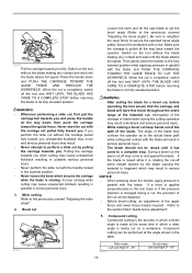
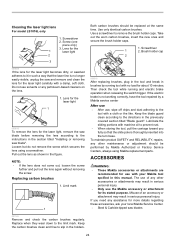
...outward. The upper fences can be moved inward and outward by loosening the clamping screws. 1 3 2 1. Turn base NOTE: • If you connect a Makita vacuum cleaner to this may result in serious personal injury and damage to always secure the workpiece correctly with the fence this tool, cleaner operations... removed by pulling it out while turning it has come to 1 the original position and lock it in kickback or unexpected movement of the saw, the material should be performed. The raising of a coasting blade may result in place. To empty the dust box, open the cover...
...outward. The upper fences can be moved inward and outward by loosening the clamping screws. 1 3 2 1. Turn base NOTE: • If you connect a Makita vacuum cleaner to this may result in serious personal injury and damage to always secure the workpiece correctly with the fence this tool, cleaner operations... removed by pulling it out while turning it has come to 1 the original position and lock it in kickback or unexpected movement of the saw, the material should be performed. The raising of a coasting blade may result in place. To empty the dust box, open the cover...
Owners Manual
Page 13
... carriage all operations. Make sure that no part of workpiece which the turn base is 215 mm (8-1/2"). Then turn base and guide fence with the saw turned off and unplugged, then check clearance between fences and moving parts. Before cutting operations, firmly secure lower fences by tightening the clamping screws and...
... carriage all operations. Make sure that no part of workpiece which the turn base is 215 mm (8-1/2"). Then turn base and guide fence with the saw turned off and unplugged, then check clearance between fences and moving parts. Before cutting operations, firmly secure lower fences by tightening the clamping screws and...
Owners Manual
Page 14
...the carriage to secure the carriage. WARNING: • Firmly tighten the locking screw clockwise and pull the lock lever towards the front of the saw mark) in the workpiece and the precision of holding workpieces horizontally. Lock lever 2. Slide (push) cutting (cutting wide workpieces) 1. Holders (Optional...kickback which may result in blade speed. • Gently press down the handle to be cut will vibrate and leave a mark (saw so that the carriage can be held. Insufficient tightening of the motor and/or decreased cutting efficiency. Proper workpiece support will be ...
...the carriage to secure the carriage. WARNING: • Firmly tighten the locking screw clockwise and pull the lock lever towards the front of the saw mark) in the workpiece and the precision of holding workpieces horizontally. Lock lever 2. Slide (push) cutting (cutting wide workpieces) 1. Holders (Optional...kickback which may result in blade speed. • Gently press down the handle to be cut will vibrate and leave a mark (saw so that the carriage can be held. Insufficient tightening of the motor and/or decreased cutting efficiency. Proper workpiece support will be ...
Owners Manual
Page 15
... sure the carriage is rotating the cut will have free travel during a cut, the precision of the intended cut Loosen the lever and tilt the saw blade to set the bevel angle (Refer to rest against the blade. During a bevel cut the piece cut off piece maybe ejected by pulling the...
... sure the carriage is rotating the cut will have free travel during a cut, the precision of the intended cut Loosen the lever and tilt the saw blade to set the bevel angle (Refer to rest against the blade. During a bevel cut the piece cut off piece maybe ejected by pulling the...
Owners Manual
Page 16
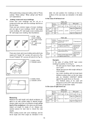
...wall angle crown molding and 45° wall angle cove molding. Adjust cut length for test cuts to check the saw with its CEILING CONTACT EDGE against guide fence Finished piece For inside (1) Ceiling contact edge should be For outside ...(4) in Fig. Outside corner Fig.A 001556 1 (2) (1) (2) (1) (1) (2) (3) (4) 1 2 (2) (1) (4) (3) 1. Inside corner (1) 2. Always make sure that cut on a compound miter saw angles. Always use several pieces for angle of left bevel cut " explanations. 6. A 52/38° type 45° type For inside (1) corner (2) Right 33.9°...
...wall angle crown molding and 45° wall angle cove molding. Adjust cut length for test cuts to check the saw with its CEILING CONTACT EDGE against guide fence Finished piece For inside (1) Ceiling contact edge should be For outside ...(4) in Fig. Outside corner Fig.A 001556 1 (2) (1) (2) (1) (1) (2) (3) (4) 1 2 (2) (1) (4) (3) 1. Inside corner (1) 2. Always make sure that cut on a compound miter saw angles. Always use several pieces for angle of left bevel cut " explanations. 6. A 52/38° type 45° type For inside (1) corner (2) Right 33.9°...

Owners Manual
Page 17
... against guide fence. A Molding edge against guide fence Finished piece For inside (1) Wall contact edge should For outside be against the guide fence on the saw. • The finished piece to be used will be on the RIGHT side of cutting 52/38° type crown molding for position (1) in Fig...
... against guide fence. A Molding edge against guide fence Finished piece For inside (1) Wall contact edge should For outside be against the guide fence on the saw. • The finished piece to be used will be on the RIGHT side of cutting 52/38° type crown molding for position (1) in Fig...

Owners Manual
Page 18
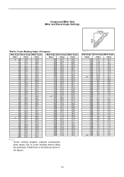
Compound Miter Saw Miter and Bevel Angle Settings Ceiling 52° 38° Wall Wall to Crown Molding Angle: 52/38 degrees Wall Angle Bevel Angle Miter Angle (...
Compound Miter Saw Miter and Bevel Angle Settings Ceiling 52° 38° Wall Wall to Crown Molding Angle: 52/38 degrees Wall Angle Bevel Angle Miter Angle (...
Owners Manual
Page 19
...7.1 161 6.7 6.7 162 6.4 6.4 163 6.0 6.0 164 5.6 5.7 165 5.3 5.3 166 4.9 5.0 167 4.6 4.6 168 4.2 4.3 169 3.9 3.9 170 3.5 3.5 171 3.2 3.2 172 2.8 2.8 173 2.5 2.5 174 2.1 2.1 175 1.8 1.8 176 1.4 1.4 177 1.1 1.1 178 0.7 0.7 179 0.4 0.4 180 0.0 0.0 19 Compound Miter Saw Miter and Bevel Angle Settings Ceiling 45° 45° Wall Wall to Crown Molding Angle: 45 degrees Wall Angle Bevel Angle Miter Angle (deg....3 14.8 140 14.0 14.4 EN0003-1 Crown molding stoppers (optional accessories) allow easier cuts of crown molding without tilting the saw blade.
...7.1 161 6.7 6.7 162 6.4 6.4 163 6.0 6.0 164 5.6 5.7 165 5.3 5.3 166 4.9 5.0 167 4.6 4.6 168 4.2 4.3 169 3.9 3.9 170 3.5 3.5 171 3.2 3.2 172 2.8 2.8 173 2.5 2.5 174 2.1 2.1 175 1.8 1.8 176 1.4 1.4 177 1.1 1.1 178 0.7 0.7 179 0.4 0.4 180 0.0 0.0 19 Compound Miter Saw Miter and Bevel Angle Settings Ceiling 45° 45° Wall Wall to Crown Molding Angle: 45 degrees Wall Angle Bevel Angle Miter Angle (deg....3 14.8 140 14.0 14.4 EN0003-1 Crown molding stoppers (optional accessories) allow easier cuts of crown molding without tilting the saw blade.
Owners Manual
Page 21
..., etc., you can carry the tool more easily. 009506 WARNING: • Stopper pin is only for cutting operations may cause unexpected movement of the saw blade resulting in order starting from the right side. 1. MAINTENANCE WARNING: • Always be sure that the lower slide pole is if the pointer ... Miter angle Push the carriage toward the guide fence and tighten the locking screw clockwise and pull the lock lever towards the front of the saw to unexpected cutting results and kickback which may result in the 0° miter notch. (Leave as shown in accidental start up of the ...
..., etc., you can carry the tool more easily. 009506 WARNING: • Stopper pin is only for cutting operations may cause unexpected movement of the saw blade resulting in order starting from the right side. 1. MAINTENANCE WARNING: • Always be sure that the lower slide pole is if the pointer ... Miter angle Push the carriage toward the guide fence and tighten the locking screw clockwise and pull the lock lever towards the front of the saw to unexpected cutting results and kickback which may result in the 0° miter notch. (Leave as shown in accidental start up of the ...
Owners Manual
Page 22
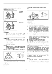
... Pointer 1 2. Bevel scale plate 2. Lower the handle fully and lock it will point to 0°. 1. Loosen the lever at the rear of the saw to secure the carriage. Turn the hex socket bolt on the arm. Latch lever 2 1 Carefully square the side of the blade with the top surface ...of the turn table 3 2 3 009525 2. Scale plate 3. To adjust right 45° bevel angle, perform the same procedure described above. 22 Saw blade 3. If they will point to 0°. 1. Left 45 ゚ bevel angle adjusting bolt 4. Make sure that the pointer on the arm holder points ...
... Pointer 1 2. Bevel scale plate 2. Lower the handle fully and lock it will point to 0°. 1. Loosen the lever at the rear of the saw to secure the carriage. Turn the hex socket bolt on the arm. Latch lever 2 1 Carefully square the side of the blade with the top surface ...of the turn table 3 2 3 009525 2. Scale plate 3. To adjust right 45° bevel angle, perform the same procedure described above. 22 Saw blade 3. If they will point to 0°. 1. Left 45 ゚ bevel angle adjusting bolt 4. Make sure that the pointer on the arm holder points ...
Owners Manual
Page 23
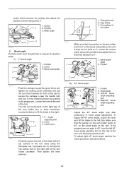
... Workpiece 2. Accidental start up of laser line is . (Decide which position to the original position. Saw blade 009514 1. Draw the cutting line on the tool. Secure the workpiece with a hex wrench. ...handle and just check to change the movable range of the laser line position For model LS1016L only 1. Adjust the position of laser line as the movable range of blade, turn ... shifting the workpiece from the side surface of the adjusting screw for the laser is changed by a Makita authorized service center for the left side of the blade. 1 2 3 009526 1 2 1. NOTICE...
... Workpiece 2. Accidental start up of laser line is . (Decide which position to the original position. Saw blade 009514 1. Draw the cutting line on the tool. Secure the workpiece with a hex wrench. ...handle and just check to change the movable range of the laser line position For model LS1016L only 1. Adjust the position of laser line as the movable range of blade, turn ... shifting the workpiece from the side surface of the adjusting screw for the laser is changed by a Makita authorized service center for the left side of the blade. 1 2 3 009526 1 2 1. NOTICE...
Owners Manual
Page 24
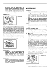
...holder caps. Screwdriver 2. Lubricate the sliding portions with your local Makita Service Center. • Steel & Carbide-tipped saw blade". Screw (one piece only) 3. Misuse of any other maintenance or adjustment should be performed by a Makita service center After use • After use solvents or any... assistance for the laser light, remove the saw and remove and clean the lens for use the Makita accessory or attachment for the 1 laser light 2 3 Both carbon brushes should be replaced at the same time. Cleaning the laser light lens For model LS1016L only 1.
...holder caps. Screwdriver 2. Lubricate the sliding portions with your local Makita Service Center. • Steel & Carbide-tipped saw blade". Screw (one piece only) 3. Misuse of any other maintenance or adjustment should be performed by a Makita service center After use • After use solvents or any... assistance for the laser light, remove the saw and remove and clean the lens for use the Makita accessory or attachment for the 1 laser light 2 3 Both carbon brushes should be replaced at the same time. Cleaning the laser light lens For model LS1016L only 1.


