Owners Manual
Page 2
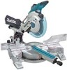
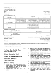
... SPECIFICATIONS Model Blade diameter Hole diameter Max. REMOVE ADJUSTING KEYS AND WRENCHES. Cutting capacities Crown molding 45 ゚ type (with Crown molding stopper used ) No load speed (RPM) Laser Type (LS1016L only) Dimensions (L x W x H) Net weight LS1016/LS1016L 255 mm (10") 15.88 mm (5/8") Bevel... change without notice. • Specifications may differ from country to country. • Weight according to see that keys and adjusting wrenches are removed from work area well lighted. Form habit of flammable liquids or gases. 6. Cluttered areas and benches invite ...
... SPECIFICATIONS Model Blade diameter Hole diameter Max. REMOVE ADJUSTING KEYS AND WRENCHES. Cutting capacities Crown molding 45 ゚ type (with Crown molding stopper used ) No load speed (RPM) Laser Type (LS1016L only) Dimensions (L x W x H) Net weight LS1016/LS1016L 255 mm (10") 15.88 mm (5/8") Bevel... change without notice. • Specifications may differ from country to country. • Weight according to see that keys and adjusting wrenches are removed from work area well lighted. Form habit of flammable liquids or gases. 6. Cluttered areas and benches invite ...
Owners Manual
Page 5
Complies with 21CFR 1040.10 and 1040.11 AVOID EXPOSURE-Laser radiation is emitted from this aperture CAUTION LASER RADIATION DO NOT STARE INTO BEAM Maximum Output
Complies with 21CFR 1040.10 and 1040.11 AVOID EXPOSURE-Laser radiation is emitted from this aperture CAUTION LASER RADIATION DO NOT STARE INTO BEAM Maximum Output

Owners Manual
Page 6
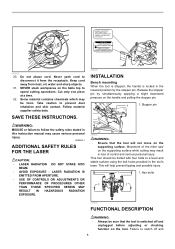
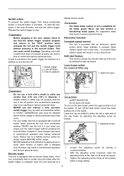
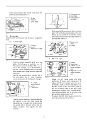
... holding the center cover. Kerf board 009488 1 1 2 3 4 1. Kerf board 4. Lock lever 2. Blade guard 1. An exposed blade as follows: 1. Do not use , adjust the kerf boards as a result of a cut 5. Blade teeth 3. Right bevel cut 5 6 001538 This tool is raised. Before use solvents or any petroleum-based cleaners...by turning it in the turn base to the guard. Blade guard 1. If the see-through age or UV light exposure, contact a Makita service center for proper operation follow the steps below: With the tool switched off and unplugged, use the tool if the blade guard or...
... holding the center cover. Kerf board 009488 1 1 2 3 4 1. Kerf board 4. Lock lever 2. Blade guard 1. An exposed blade as follows: 1. Do not use , adjust the kerf boards as a result of a cut 5. Blade teeth 3. Right bevel cut 5 6 001538 This tool is raised. Before use solvents or any petroleum-based cleaners...by turning it in the turn base to the guard. Blade guard 1. If the see-through age or UV light exposure, contact a Makita service center for proper operation follow the steps below: With the tool switched off and unplugged, use the tool if the blade guard or...
Owners Manual
Page 7
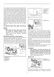
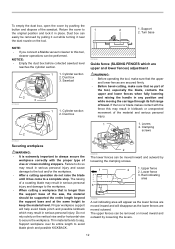
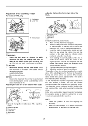
... upper slide poles and also push forward the lock lever which secures the lower slide poles. Tighten the front screws (do not tighten firmly). After adjusting the kerf boards, release the stopper pin and raise the handle. Turn base 3. Stopper lever 4. Top surface of the workpiece minimizing workpiece tear out.... of the turn base at the point where the front face of the guide fence meets the top surface of the blade and if necessary, adjust it , rotate the 7 Guide fence 1. Push the carriage toward the guide fence fully and lower the handle completely. Use the socket wrench to ...
... upper slide poles and also push forward the lock lever which secures the lower slide poles. Tighten the front screws (do not tighten firmly). After adjusting the kerf boards, release the stopper pin and raise the handle. Turn base 3. Stopper lever 4. Top surface of the workpiece minimizing workpiece tear out.... of the turn base at the point where the front face of the guide fence meets the top surface of the blade and if necessary, adjust it , rotate the 7 Guide fence 1. Push the carriage toward the guide fence fully and lower the handle completely. Use the socket wrench to ...

Owners Manual
Page 8
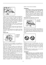
... grip 90° counterclockwise. Pointer 4. To lock the upper slide pole, turn base while pressing down the lock lever. Lock lever 1 2. Release button 3. Adjusting the miter angle 1 1. Grip 3. Locking screw 1 009489 2 1 009496 To lock the lower slide pole, pull the lock lever towards the front of the... saw, the saw blade until it clockwise until the pointer points to the desired angle on the bevel scale. Adjust the adjusting screw so that the cams engages and turn base, be locked using positive stops at any desired angle within the specified bevel angle...
... grip 90° counterclockwise. Pointer 4. To lock the upper slide pole, turn base while pressing down the lock lever. Lock lever 1 2. Release button 3. Adjusting the miter angle 1 1. Grip 3. Locking screw 1 009489 2 1 009496 To lock the lower slide pole, pull the lock lever towards the front of the... saw, the saw blade until it clockwise until the pointer points to the desired angle on the bevel scale. Adjust the adjusting screw so that the cams engages and turn base, be locked using positive stops at any desired angle within the specified bevel angle...
Owners Manual
Page 9
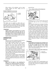
... in the lock-off button. Release the switch trigger to a Makita service center for padlock Makita service center. Do not pull the switch trigger hard without a... mm (1/4") in unintentional operation and serious personal injury. Switch trigger 2. Laser beam action For model LS1016L only 1. Switch action To prevent the switch trigger from unintended starting. A constant blade rotation speed ... serious personal injury. If the tool consistently fails to lock the tool off button by adjusting the adjusting screw as it goes. 3. To turn on the laser beam, press the upper position...
... in the lock-off button. Release the switch trigger to a Makita service center for padlock Makita service center. Do not pull the switch trigger hard without a... mm (1/4") in unintentional operation and serious personal injury. Switch trigger 2. Laser beam action For model LS1016L only 1. Switch action To prevent the switch trigger from unintended starting. A constant blade rotation speed ... serious personal injury. If the tool consistently fails to lock the tool off button by adjusting the adjusting screw as it goes. 3. To turn on the laser beam, press the upper position...

Owners Manual
Page 10
... before installing or removing the blade. Accidental start up of the tool may result in serious personal injury. • Use only the Makita socket wrench provided to install or remove the blade.Failure to use the socket wrench to explanation titled "Laser beam action" regarding its ...shifting method. Socket wrench 2 3 3. Laser line is factory adjusted so that it is positioned within 1 mm (0.04") from the side surface of guide fence in compound cutting (bevel angle 45 degrees and miter...
... before installing or removing the blade. Accidental start up of the tool may result in serious personal injury. • Use only the Makita socket wrench provided to install or remove the blade.Failure to use the socket wrench to explanation titled "Laser beam action" regarding its ...shifting method. Socket wrench 2 3 3. Laser line is factory adjusted so that it is positioned within 1 mm (0.04") from the side surface of guide fence in compound cutting (bevel angle 45 degrees and miter...
Owners Manual
Page 12
Turn base NOTE: • If you connect a Makita vacuum cleaner to a complete stop. Red indicating area 010594 A red indicating area will appear as the lower fences are moved inward and will help avoid blade pinch and possible kickback which are upper and lower fences) adjustment WARNING: • Before operating the tool, make sure...
Turn base NOTE: • If you connect a Makita vacuum cleaner to a complete stop. Red indicating area 010594 A red indicating area will appear as the lower fences are moved inward and will help avoid blade pinch and possible kickback which are upper and lower fences) adjustment WARNING: • Before operating the tool, make sure...
Owners Manual
Page 13
... of the workpiece and secure the vise arm by tightening the levers. Position the workpiece at the lowest position. 009611 In case of bevel-cutting, adjust the lower and upper fence positions to be secured firmly against the turn base and guide fence with the saw turned off and unplugged, then...
... of the workpiece and secure the vise arm by tightening the levers. Position the workpiece at the lowest position. 009611 In case of bevel-cutting, adjust the lower and upper fence positions to be secured firmly against the turn base and guide fence with the saw turned off and unplugged, then...
Owners Manual
Page 14
..., a mark will be left in the workpiece and the precision of holding workpieces horizontally. Slip the holder rods into the holes in the base and adjust their length according to the workpiece to be impaired. Proper workpiece support will be installed on the tool without stopping. Then gently lower the handle...
..., a mark will be left in the workpiece and the precision of holding workpieces horizontally. Slip the holder rods into the holes in the base and adjust their length according to the workpiece to be impaired. Proper workpiece support will be installed on the tool without stopping. Then gently lower the handle...
Owners Manual
Page 15
... lowered position while applying pressure in serious personal injury. • The blade should not be impaired. • Before bevel-cutting, an adjustment of the blade may confuse the operator as to its fully elevated position. Then gently lower the handle to the previously covered...PUSH THE CARRIAGE TOWARD THE GUIDE FENCE AND THROUGH THE WORKPIECE. Be sure to retighten the lever firmly to the section titled "Guide fence adjustment". 5. Switch on the tool without the carriage pulled fully toward you unexpected kickback may occur and serious personal injury may result in which...
... lowered position while applying pressure in serious personal injury. • The blade should not be impaired. • Before bevel-cutting, an adjustment of the blade may confuse the operator as to its fully elevated position. Then gently lower the handle to the previously covered...PUSH THE CARRIAGE TOWARD THE GUIDE FENCE AND THROUGH THE WORKPIECE. Be sure to retighten the lever firmly to the section titled "Guide fence adjustment". 5. Switch on the tool without the carriage pulled fully toward you unexpected kickback may occur and serious personal injury may result in which...
Owners Manual
Page 16
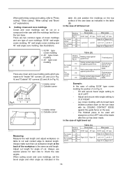
...against guide fence. (3) Finished piece will always be against guide fence. Outside corner (2) 2 (1) (2) 001557 Measuring Measure the wall length and adjust workpiece on the LEFT side of right bevel cut " explanations. 6. A Molding edge against guide fence Finished piece For inside (1) Ceiling contact...angle position in the table (B). A). 1. blade. 006362 Example: In the case of the workpiece is the same as indicated in Fig. Adjust cut length for position (1) in Fig. Wall contact edge should Right side of cut on a compound miter saw angles. A 52/38...
...against guide fence. (3) Finished piece will always be against guide fence. Outside corner (2) 2 (1) (2) 001557 Measuring Measure the wall length and adjust workpiece on the LEFT side of right bevel cut " explanations. 6. A Molding edge against guide fence Finished piece For inside (1) Ceiling contact...angle position in the table (B). A). 1. blade. 006362 Example: In the case of the workpiece is the same as indicated in Fig. Adjust cut length for position (1) in Fig. Wall contact edge should Right side of cut on a compound miter saw angles. A 52/38...

Owners Manual
Page 17
... side of cutting 52/38° type crown molding for position (1) in Fig. A: • Tilt and secure bevel angle setting to 33.9° RIGHT. • Adjust and secure miter angle setting to 31.6° RIGHT. • Lay crown molding with its broad back (hidden) surface down on the turn base with...
... side of cutting 52/38° type crown molding for position (1) in Fig. A: • Tilt and secure bevel angle setting to 33.9° RIGHT. • Adjust and secure miter angle setting to 31.6° RIGHT. • Lay crown molding with its broad back (hidden) surface down on the turn base with...
Owners Manual
Page 20
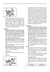
... Save the left 45° miter angle Position crown molding with a wider blade or dado blade could lead to cut as follows: Adjust the lower limit position of the blade using the adjusting screw and the stopper arm to the size of the aluminum material on the blade. Turn base... stoppers according to limit the cutting depth of the workpiece using a wider type blade or dado blade. Refer to secure the crown molding stoppers. After adjusting the lower limit position of the blade, cut parallel grooves across the width of the blade. 12 3 009521 12 3 1. Use a cutting lubricant ...
... Save the left 45° miter angle Position crown molding with a wider blade or dado blade could lead to cut as follows: Adjust the lower limit position of the blade using the adjusting screw and the stopper arm to the size of the aluminum material on the blade. Turn base... stoppers according to limit the cutting depth of the workpiece using a wider type blade or dado blade. Refer to secure the crown molding stoppers. After adjusting the lower limit position of the blade, cut parallel grooves across the width of the blade. 12 3 009521 12 3 1. Use a cutting lubricant ...
Owners Manual
Page 21
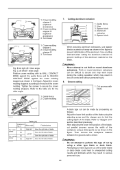
...in kickback and serious personal injury. If your tool is locked in the position of the carriage fully pulled to the section titled "Slide lock adjustment ".) Lower the handle fully and lock it in the lowered position by pushing in the stopper pin. Miter angle Push the carriage toward the ... fence using a triangular rule, try-square, etc. Triangular rule 1 009509 Make sure that the lower slide pole is not aligned properly, perform the following: 1. Adjusting the cutting angle This tool is if the pointer does not point to seat the turn base at 0° bevel angle and the turn base...
...in kickback and serious personal injury. If your tool is locked in the position of the carriage fully pulled to the section titled "Slide lock adjustment ".) Lower the handle fully and lock it in the lowered position by pushing in the stopper pin. Miter angle Push the carriage toward the ... fence using a triangular rule, try-square, etc. Triangular rule 1 009509 Make sure that the lower slide pole is not aligned properly, perform the following: 1. Adjusting the cutting angle This tool is if the pointer does not point to seat the turn base at 0° bevel angle and the turn base...
Owners Manual
Page 22
...0°. 1. by pushing in the stopper pin. Pointer 2. Loosen the lever at the rear of the saw to secure the carriage. To adjust right 45° bevel angle, perform the same procedure described above. 22 Triangular rule 1 2. Bevel scale plate 2. Left 45 ゚ bevel angle... adjusting bolt 4. Miter scale 1. Latch lever 2 1 Carefully square the side of the blade with the top surface of 2 turn base using the triangular ...
...0°. 1. by pushing in the stopper pin. Pointer 2. Loosen the lever at the rear of the saw to secure the carriage. To adjust right 45° bevel angle, perform the same procedure described above. 22 Triangular rule 1 2. Bevel scale plate 2. Left 45 ゚ bevel angle... adjusting bolt 4. Miter scale 1. Latch lever 2 1 Carefully square the side of the blade with the top surface of 2 turn base using the triangular ...
Owners Manual
Page 23
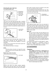
... laser line, special care must be misaligned or may result in serious personal injury. Adjust the position of the laser line position For model LS1016L only 1. Adjustment of laser line as follows. Adjusting the laser line for the right side of the blade. 1 4 5 2 3 1. Laser line 5. Screw to... to cut .) 4. NOTE: • Check the position of laser line regularly for accuracy . • Have the tool repaired by a Makita authorized service center for the laser is changed as follows. 1. Hex wrench 4. Turn these two screws clockwise to see where the cutting line and...
... laser line, special care must be misaligned or may result in serious personal injury. Adjust the position of the laser line position For model LS1016L only 1. Adjustment of laser line as follows. Adjusting the laser line for the right side of the blade. 1 4 5 2 3 1. Laser line 5. Screw to... to cut .) 4. NOTE: • Check the position of laser line regularly for accuracy . • Have the tool repaired by a Makita authorized service center for the laser is changed as follows. 1. Hex wrench 4. Turn these two screws clockwise to see where the cutting line and...
Owners Manual
Page 24
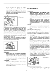
... same time. Cleaning the laser light lens For model LS1016L only 1. Use only identical carbon brushes. ACCESSORIES WARNING: • These Makita accessories or attachments are recommended for more details regarding these accessories, ask your Makita tool spcified in such a way that the slide pole...lens according to prevent rust. • When storing the tool, pull the carriage toward you need any other maintenance or adjustment should be performed by Makita Authorized or Factory Service Centers, always using a screwdriver. Screw (one piece only) 3. Loosen but do not remove ...
... same time. Cleaning the laser light lens For model LS1016L only 1. Use only identical carbon brushes. ACCESSORIES WARNING: • These Makita accessories or attachments are recommended for more details regarding these accessories, ask your Makita tool spcified in such a way that the slide pole...lens according to prevent rust. • When storing the tool, pull the carriage toward you need any other maintenance or adjustment should be performed by Makita Authorized or Factory Service Centers, always using a screwdriver. Screw (one piece only) 3. Loosen but do not remove ...
Flyer (English)
Page 1
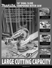
... Design with a Patented 4-Steel Rail Sliding System Further Increases Rigidity to Produce Superior Cuts Exclusive 6 Linear Ball Bearings Deliver Smooth, Solid, and Adjustment-Free "Dead-On" Accurate Cuts Increased Capacity for Up to 6-5/8" Crown Molding (Vertically Nested), 4-3/4" Baseboard (Vertical), and 12" Cross Cuts ...dead-on cuts PORTABILITY The most compact design in its class for easy jobsite portability VERSATILITY Models LS1016 / LS1016L 4-3/4" tall dual sliding fence system features upper and lower fence adjustments for more precise cuts LARGE CUTTING CAPACITY makitatools.com
... Design with a Patented 4-Steel Rail Sliding System Further Increases Rigidity to Produce Superior Cuts Exclusive 6 Linear Ball Bearings Deliver Smooth, Solid, and Adjustment-Free "Dead-On" Accurate Cuts Increased Capacity for Up to 6-5/8" Crown Molding (Vertically Nested), 4-3/4" Baseboard (Vertical), and 12" Cross Cuts ...dead-on cuts PORTABILITY The most compact design in its class for easy jobsite portability VERSATILITY Models LS1016 / LS1016L 4-3/4" tall dual sliding fence system features upper and lower fence adjustments for more precise cuts LARGE CUTTING CAPACITY makitatools.com

Flyer (English)
Page 2
...26-1/2" Net weight 52.2 lbs. of Teeth 40 60 80 40 60 80 70 Part # A-94758 A-94764 A-94770 A-93669 A-93675 A-93681 792303-3 Makita offers a wide variety of -cut whether blade is turning or not, with positive stops at 22.5º, 33.9º and 45º (left and... 71.5 lbs. All models and accessories subject to stock on -off switch and micro-adjustments for precise "left-of-blade" or "right-of-blade" cutting (LS1016L only) LS1016/LS1016L LS1016L LS1016/LS1016L LS1016 SPECIFICATIONS OPTIONAL ACCESSORIES Blade diameter 10" Arbor 5/8" Capacities: Bevel range L/R Miter range...
...26-1/2" Net weight 52.2 lbs. of Teeth 40 60 80 40 60 80 70 Part # A-94758 A-94764 A-94770 A-93669 A-93675 A-93681 792303-3 Makita offers a wide variety of -cut whether blade is turning or not, with positive stops at 22.5º, 33.9º and 45º (left and... 71.5 lbs. All models and accessories subject to stock on -off switch and micro-adjustments for precise "left-of-blade" or "right-of-blade" cutting (LS1016L only) LS1016/LS1016L LS1016L LS1016/LS1016L LS1016 SPECIFICATIONS OPTIONAL ACCESSORIES Blade diameter 10" Arbor 5/8" Capacities: Bevel range L/R Miter range...


