Owners Manual
Page 5
Complies with 21CFR 1040.10 and 1040.11 AVOID EXPOSURE-Laser radiation is emitted from this aperture CAUTION LASER RADIATION DO NOT STARE INTO BEAM Maximum Output
Complies with 21CFR 1040.10 and 1040.11 AVOID EXPOSURE-Laser radiation is emitted from this aperture CAUTION LASER RADIATION DO NOT STARE INTO BEAM Maximum Output

Owners Manual
Page 8
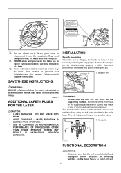
... the rear of the tool counterclockwise. When you have moved the grip to the position where the pointer points to the desired angle on the miter scale, turn the grip 90° counterclockwise to lock the turn the locking screw clockwise. 8 Latch lever 1. When the latch lever is fully raised. &#... 1 1. CAUTION: • After changing the miter angle, always secure the turn base while pressing down the lock lever. stopper arm in the direction of the arrow as shown in the figure fully while supporting the weight of the saw head so as to release the pressure on the lock pin. Lever ...
... the rear of the tool counterclockwise. When you have moved the grip to the position where the pointer points to the desired angle on the miter scale, turn the grip 90° counterclockwise to lock the turn the locking screw clockwise. 8 Latch lever 1. When the latch lever is fully raised. &#... 1 1. CAUTION: • After changing the miter angle, always secure the turn base while pressing down the lock lever. stopper arm in the direction of the arrow as shown in the figure fully while supporting the weight of the saw head so as to release the pressure on the lock pin. Lever ...

Owners Manual
Page 10
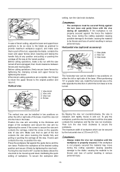
... start up of the tool may result in serious personal injury. • Use only the Makita socket wrench provided to install or remove the blade.Failure to use the socket wrench to loosen... 009495 The socket wrench is stored as shown in compound cutting (bevel angle 45 degrees and miter angle right 45 degrees). Socket wrench 2 3 3. Laser line is factory adjusted so that... workpiece • Shift the laser line to see because of the wrench holder. Installing or removing saw blade WARNING: • Always be sure that it counterclockwise. Center cover 1 2. NOTE: •...
... start up of the tool may result in serious personal injury. • Use only the Makita socket wrench provided to install or remove the blade.Failure to use the socket wrench to loosen... 009495 The socket wrench is stored as shown in compound cutting (bevel angle 45 degrees and miter angle right 45 degrees). Socket wrench 2 3 3. Laser line is factory adjusted so that... workpiece • Shift the laser line to see because of the wrench holder. Installing or removing saw blade WARNING: • Always be sure that it counterclockwise. Center cover 1 2. NOTE: •...
Owners Manual
Page 13
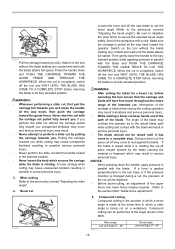
... vise 4 1. WARNING: • The workpiece must be secured firmly against the guide fence and the turn base and guide fence with the saw turned off and unplugged, then check clearance between fences and moving parts. Vise plate 2. Turning the vise knob to 90° counterclockwise allows ...(8-1/2"). Vise arm 3. Vise nut 3. Screw setting, turn the vise knob clockwise to secure the workpiece. When performing 15° or greater miter cuts, install the horizontal vise on the opposite side of vise arm. Position the vise arm according to the thickness and shape of the workpiece...
... vise 4 1. WARNING: • The workpiece must be secured firmly against the guide fence and the turn base and guide fence with the saw turned off and unplugged, then check clearance between fences and moving parts. Vise plate 2. Turning the vise knob to 90° counterclockwise allows ...(8-1/2"). Vise arm 3. Vise nut 3. Screw setting, turn the vise knob clockwise to secure the workpiece. When performing 15° or greater miter cuts, install the horizontal vise on the opposite side of vise arm. Position the vise arm according to the thickness and shape of the workpiece...
Owners Manual
Page 15
...8226; When pressing down and PUSH THE CARRIAGE TOWARD THE GUIDE FENCE AND THROUGH THE WORKPIECE. Refer to secure the selected bevel angle safely. Miter cutting Refer to the previously covered "Adjusting the bevel angle"). Interruption of the carriage or blade travel during a cut, the precision of ...blade path while cutting and contact with a vise. When the cut Loosen the lever and tilt the saw blade to set the bevel angle (Refer to the previously covered "Adjusting the miter angle". 4. 009504 Pull the carriage toward the guide fence. Make sure the carriage is completed, ...
...8226; When pressing down and PUSH THE CARRIAGE TOWARD THE GUIDE FENCE AND THROUGH THE WORKPIECE. Refer to secure the selected bevel angle safely. Miter cutting Refer to the previously covered "Adjusting the bevel angle"). Interruption of the carriage or blade travel during a cut, the precision of ...blade path while cutting and contact with a vise. When the cut Loosen the lever and tilt the saw blade to set the bevel angle (Refer to the previously covered "Adjusting the miter angle". 4. 009504 Pull the carriage toward the guide fence. Make sure the carriage is completed, ...
Owners Manual
Page 16
...contact edge to "Press cutting", "Slide cutting", "Miter cutting" and "Bevel cut has been made to check the saw base as wall length. Finished piece will be on the corner Ceiling contact edge should be cut on a compound miter saw with its CEILING CONTACT EDGE against the guide fence on... the saw. • The finished piece to be used will always be against guide fence Finished piece For inside (1)...
...contact edge to "Press cutting", "Slide cutting", "Miter cutting" and "Bevel cut has been made to check the saw base as wall length. Finished piece will be on the corner Ceiling contact edge should be cut on a compound miter saw with its CEILING CONTACT EDGE against the guide fence on... the saw. • The finished piece to be used will always be against guide fence Finished piece For inside (1)...

Owners Manual
Page 17
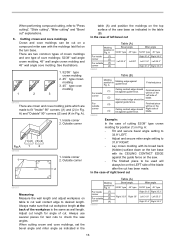
A: • Tilt and secure bevel angle setting to 33.9° RIGHT. • Adjust and secure miter angle setting to 31.6° RIGHT. • Lay crown molding with its broad back (hidden) surface down on the turn base with its WALL CONTACT ... fence on the RIGHT side of against guide fence. A Molding edge against guide fence Finished piece For inside (1) Wall contact edge should be on the saw. • The finished piece to be used will always be against guide fence. Ceiling contact edge should be on the corner (4) Wall contact edge should...
A: • Tilt and secure bevel angle setting to 33.9° RIGHT. • Adjust and secure miter angle setting to 31.6° RIGHT. • Lay crown molding with its broad back (hidden) surface down on the turn base with its WALL CONTACT ... fence on the RIGHT side of against guide fence. A Molding edge against guide fence Finished piece For inside (1) Wall contact edge should be on the saw. • The finished piece to be used will always be against guide fence. Ceiling contact edge should be on the corner (4) Wall contact edge should...

Owners Manual
Page 18
Compound Miter Saw Miter and Bevel Angle Settings Ceiling 52° 38° Wall Wall to Crown Molding Angle: 52/38 degrees Wall Angle Bevel Angle Miter Angle (deg.) (deg.) (deg.) 60 43.0 46.8 61 42... 29.0 97 31.5 28.6 98 31.1 28.2 99 30.8 27.7 100 30.4 27.3 Wall Angle Bevel Angle Miter Angle (deg.) (deg.) (deg.) 101 30.1 26.9 102 29.7 26.5 103 29.4 26.1 104 29.0 25...137 16.8 13.6 138 16.4 13.3 139 16.0 13.0 140 15.6 12.8 EN0002-1 000031 Wall Angle Bevel Angle Miter Angle (deg.) (deg.) (deg.) 141 15.3 12.3 142 14.9 12.0 143 14.5 11.6 144 14.1 11...
Compound Miter Saw Miter and Bevel Angle Settings Ceiling 52° 38° Wall Wall to Crown Molding Angle: 52/38 degrees Wall Angle Bevel Angle Miter Angle (deg.) (deg.) (deg.) 60 43.0 46.8 61 42... 29.0 97 31.5 28.6 98 31.1 28.2 99 30.8 27.7 100 30.4 27.3 Wall Angle Bevel Angle Miter Angle (deg.) (deg.) (deg.) 101 30.1 26.9 102 29.7 26.5 103 29.4 26.1 104 29.0 25...137 16.8 13.6 138 16.4 13.3 139 16.0 13.0 140 15.6 12.8 EN0002-1 000031 Wall Angle Bevel Angle Miter Angle (deg.) (deg.) (deg.) 141 15.3 12.3 142 14.9 12.0 143 14.5 11.6 144 14.1 11...
Owners Manual
Page 19
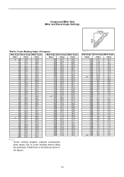
Compound Miter Saw Miter and Bevel Angle Settings Ceiling 45° 45° Wall Wall to Crown Molding Angle: 45 degrees Wall Angle Bevel Angle Miter Angle (deg.) (deg.) (deg.) 60 37.8 50.8 61 37.5 50.2 62 37.3 49.6 63 37.1 49.1 64 36.8 48.5 65 36.6 48.0 66 36.4 ... 14.0 14.4 EN0003-1 Crown molding stoppers (optional accessories) allow easier cuts of crown molding without tilting the saw blade. Install them on the base as shown in the figures. 000032 Wall Angle Bevel Angle Miter Angle (deg.) (deg.) (deg.) 141 13.7 14.1 142 13.3 13.7 143 13.0 13.3 144 12.6 12.9...
Compound Miter Saw Miter and Bevel Angle Settings Ceiling 45° 45° Wall Wall to Crown Molding Angle: 45 degrees Wall Angle Bevel Angle Miter Angle (deg.) (deg.) (deg.) 60 37.8 50.8 61 37.5 50.2 62 37.3 49.6 63 37.1 49.1 64 36.8 48.5 65 36.6 48.0 66 36.4 ... 14.0 14.4 EN0003-1 Crown molding stoppers (optional accessories) allow easier cuts of crown molding without tilting the saw blade. Install them on the base as shown in the figures. 000032 Wall Angle Bevel Angle Miter Angle (deg.) (deg.) (deg.) 141 13.7 14.1 142 13.3 13.7 143 13.0 13.3 144 12.6 12.9...
Owners Manual
Page 21
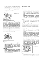
... or the like. CAUTION: • Always secure all moving portions before attempting to 0° on the miter scale. NOTICE: • Never use of the tool which may result in accidental start up of the ... in the stopper pin. Turn the turn base in the 0° miter notch. (Leave as shown in the position of the saw to operator and the upper poles are locked in the figure. Then ...securely tighten the hex socket bolts on the miter scale. Carrying tool 1 1. If portions ...
... or the like. CAUTION: • Always secure all moving portions before attempting to 0° on the miter scale. NOTICE: • Never use of the tool which may result in accidental start up of the ... in the stopper pin. Turn the turn base in the 0° miter notch. (Leave as shown in the position of the saw to operator and the upper poles are locked in the figure. Then ...securely tighten the hex socket bolts on the miter scale. Carrying tool 1 1. If portions ...
Owners Manual
Page 22
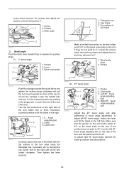
...of the tool. Lower the handle fully and lock it will point to 0°. 1. Loosen the lever at the rear of the saw to secure the carriage. Pointer 2. Right 45 ゚ bevel angle adjusting bolt Adjust the 45° bevel angle only after performing ...the triangular rule, try-square, etc. Then tighten the lever securely. 2 009490 (2) 45° bevel angle 009608 1 2 3 4 1. Screw 1 2. Lever 3. Saw blade 3. Miter scale 1. Bevel scale plate 2 001819 1 Make sure that the pointers on the arm holder point to release the positive stops. (1) 0° bevel angle 1. Lever 3....
...of the tool. Lower the handle fully and lock it will point to 0°. 1. Loosen the lever at the rear of the saw to secure the carriage. Pointer 2. Right 45 ゚ bevel angle adjusting bolt Adjust the 45° bevel angle only after performing ...the triangular rule, try-square, etc. Then tighten the lever securely. 2 009490 (2) 45° bevel angle 009608 1 2 3 4 1. Screw 1 2. Lever 3. Saw blade 3. Miter scale 1. Bevel scale plate 2 001819 1 Make sure that the pointers on the arm holder point to release the positive stops. (1) 0° bevel angle 1. Lever 3....
Owners Manual
Page 25
...Dust bag • Crown molding stopper set • Triangular rule • Dust box • Hex wrench (for LS1016L) MAKITA LIMITED ONE YEAR WARRANTY Warranty Policy Every Makita tool is thoroughly inspected and tested before leaving the factory. EN0006-1 25 For smoother cross grain cuts. If inspection ... period, return the COMPLETE tool, freight prepaid, to you may not apply to one of original purchase. Miter saw blades and other rights which vary from the date of Makita's Factory or Authorized Service Centers. This Warranty gives you specific legal rights, and you .
...Dust bag • Crown molding stopper set • Triangular rule • Dust box • Hex wrench (for LS1016L) MAKITA LIMITED ONE YEAR WARRANTY Warranty Policy Every Makita tool is thoroughly inspected and tested before leaving the factory. EN0006-1 25 For smoother cross grain cuts. If inspection ... period, return the COMPLETE tool, freight prepaid, to you may not apply to one of original purchase. Miter saw blades and other rights which vary from the date of Makita's Factory or Authorized Service Centers. This Warranty gives you specific legal rights, and you .

Parts Breakdown
Page 7
258 259 272 275 1,001 1,002 1,003 1,004 1,005 1,006 266042-6 451412-4 942151-2 253313-0 122852-0 122854-6 762001-3 783208-8 782232-8 A-93675 Parts Breakdown TAPPING SCREW BIND CT 4X20, 9046 CASE, LS1016 SPRING WASHER 6, 5007NB THIN WASHER, 4340FCT DUST BAG ASS'Y, LS1016 VISE ASS'Y, LS1016L TRIANGLE RULE, LS1011 HEX WRENCH 2.5, LS1016L BOX WRENCH 13, LS1016 10X5/8 60T MITER SAW BLADE, LS1040 LS1016L 1 1 1 1 1 1 1 1 1 1 Page 7 of 7 8/18/2010
258 259 272 275 1,001 1,002 1,003 1,004 1,005 1,006 266042-6 451412-4 942151-2 253313-0 122852-0 122854-6 762001-3 783208-8 782232-8 A-93675 Parts Breakdown TAPPING SCREW BIND CT 4X20, 9046 CASE, LS1016 SPRING WASHER 6, 5007NB THIN WASHER, 4340FCT DUST BAG ASS'Y, LS1016 VISE ASS'Y, LS1016L TRIANGLE RULE, LS1011 HEX WRENCH 2.5, LS1016L BOX WRENCH 13, LS1016 10X5/8 60T MITER SAW BLADE, LS1040 LS1016L 1 1 1 1 1 1 1 1 1 1 Page 7 of 7 8/18/2010

Flyer (English)
Page 1
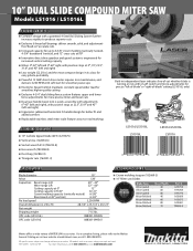
... CROWN MOLDING CAPACITY IN ITS CLASS 10" Slide Miter Saw with the Crown Molding Cutting Capacity of a 12" Saw Compact Design with a Patented 4-Steel Rail Sliding System Further Increases Rigidity to Produce Superior Cuts Exclusive 6 Linear Ball Bearings Deliver Smooth, Solid, and ...patented 4-steel rail sliding system deliver dead-on cuts PORTABILITY The most compact design in its class for easy jobsite portability VERSATILITY Models LS1016 / LS1016L 4-3/4" tall dual sliding fence system features upper and lower fence adjustments for more precise cuts LARGE CUTTING CAPACITY makitatools.com
... CROWN MOLDING CAPACITY IN ITS CLASS 10" Slide Miter Saw with the Crown Molding Cutting Capacity of a 12" Saw Compact Design with a Patented 4-Steel Rail Sliding System Further Increases Rigidity to Produce Superior Cuts Exclusive 6 Linear Ball Bearings Deliver Smooth, Solid, and ...patented 4-steel rail sliding system deliver dead-on cuts PORTABILITY The most compact design in its class for easy jobsite portability VERSATILITY Models LS1016 / LS1016L 4-3/4" tall dual sliding fence system features upper and lower fence adjustments for more precise cuts LARGE CUTTING CAPACITY makitatools.com
Flyer (English)
Page 2
...º (left and right), with on-off switch and micro-adjustments for more information, call 1-800-4MAKITA. 10" DUAL SLIDE COMPOUND MITER SAW Models LS1016 / LS1016L FEATURES & BENEFITS I Compact design with a patented 4-Steel Rail Sliding System further increases rigidity to produce superior cuts I Exclusive 6 linear ... or not, with positive stops at 22.5º, 33.9º and 45º (left -of-blade" or "right-of MITER SAW accessories. For a complete listing, please refer to the Makita General Catalog, or visit our website at 45º (vertical) 45º - 45º 52º - 60º...
...º (left and right), with on-off switch and micro-adjustments for more information, call 1-800-4MAKITA. 10" DUAL SLIDE COMPOUND MITER SAW Models LS1016 / LS1016L FEATURES & BENEFITS I Compact design with a patented 4-Steel Rail Sliding System further increases rigidity to produce superior cuts I Exclusive 6 linear ... or not, with positive stops at 22.5º, 33.9º and 45º (left -of-blade" or "right-of MITER SAW accessories. For a complete listing, please refer to the Makita General Catalog, or visit our website at 45º (vertical) 45º - 45º 52º - 60º...


