Owners Manual
Page 2
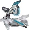
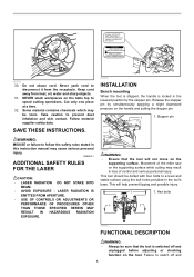
...Form habit of research and development, the specifications herein are removed from tool before turning it was designed. 9. KEEP WORK AREA CLEAN. USE RIGHT TOOL. Learn the tool's applications and limitations, as well as the specific potential hazards peculiar to rain. MAKE WORKSHOP KID PROOF... with Horizontal vise used) No load speed (RPM) Laser Type (LS1016L only) Dimensions (L x W x H) Net weight LS1016/LS1016L 255 mm (10") 15.88 mm (5/8") Bevel angle 0° 71 mm x 305 mm (2-13/16...
...Form habit of research and development, the specifications herein are removed from tool before turning it was designed. 9. KEEP WORK AREA CLEAN. USE RIGHT TOOL. Learn the tool's applications and limitations, as well as the specific potential hazards peculiar to rain. MAKE WORKSHOP KID PROOF... with Horizontal vise used) No load speed (RPM) Laser Type (LS1016L only) Dimensions (L x W x H) Net weight LS1016/LS1016L 255 mm (10") 15.88 mm (5/8") Bevel angle 0° 71 mm x 305 mm (2-13/16...
Owners Manual
Page 3
.... WEAR PROPER APPAREL. Do not wear loose clothing, gloves, neckties, rings, bracelets, or other conditions that specified on cord length and nameplate ampere rating. Use clamps or a vise to hold work into a blade or cutter against the direction of rotation of the tool, a guard or other ). DO NOT OVERREACH...accessories may get caught in loss of injury to carry the current your hand and it comes to install the proper outlet. DIRECTION OF FEED. USE PROPER EXTENSION CORD. An undersized cord will fit in . 17. The smaller the gage number, the heavier the cord. AWG 18 16 ...
.... WEAR PROPER APPAREL. Do not wear loose clothing, gloves, neckties, rings, bracelets, or other conditions that specified on cord length and nameplate ampere rating. Use clamps or a vise to hold work into a blade or cutter against the direction of rotation of the tool, a guard or other ). DO NOT OVERREACH...accessories may get caught in loss of injury to carry the current your hand and it comes to install the proper outlet. DIRECTION OF FEED. USE PROPER EXTENSION CORD. An undersized cord will fit in . 17. The smaller the gage number, the heavier the cord. AWG 18 16 ...
Owners Manual
Page 4
... guide fence with any coasting blade. Unplug tool before operation. 18. Check the blade carefully for proper closing before operation. Never use tool where operator positioning would be lulled into the open position. 4. If blade begins to bind during repetitive, monotonous operations. Be... operations. Never clamp or tie the blade guard into a false sense of injury, return carriage to the full rear position after each use. Always secure all times, especially during a cutting operation, do not continue to damage the arbor, flanges (especially the installing surface) ...
... guide fence with any coasting blade. Unplug tool before operation. 18. Check the blade carefully for proper closing before operation. Never use tool where operator positioning would be lulled into the open position. 4. If blade begins to bind during repetitive, monotonous operations. Be... operations. Never clamp or tie the blade guard into a false sense of injury, return carriage to the full rear position after each use. Always secure all times, especially during a cutting operation, do not continue to damage the arbor, flanges (especially the installing surface) ...
Owners Manual
Page 5
Complies with 21CFR 1040.10 and 1040.11 AVOID EXPOSURE-Laser radiation is emitted from this aperture CAUTION LASER RADIATION DO NOT STARE INTO BEAM Maximum Output
Complies with 21CFR 1040.10 and 1040.11 AVOID EXPOSURE-Laser radiation is emitted from this aperture CAUTION LASER RADIATION DO NOT STARE INTO BEAM Maximum Output

Owners Manual
Page 6
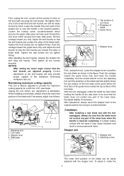
... automatically. In the interest of defeated guarding may result in serious personal injury from accidental start-up. Operation of a cut. Do not use the tool if the blade guard or spring are factory adjusted so that the blade and/or workpiece is provided with a damaged, faulty ... kerf board 1. Straight cut 5. If the see-through age or UV light exposure, contact a Makita service center for proper operation follow the steps below: With the tool switched off and unplugged, use , adjust the kerf boards as a result of your personal safety, always maintain the blade guard in...
... automatically. In the interest of defeated guarding may result in serious personal injury from accidental start-up. Operation of a cut. Do not use the tool if the blade guard or spring are factory adjusted so that the blade and/or workpiece is provided with a damaged, faulty ... kerf board 1. Straight cut 5. If the see-through age or UV light exposure, contact a Makita service center for proper operation follow the steps below: With the tool switched off and unplugged, use , adjust the kerf boards as a result of your personal safety, always maintain the blade guard in...
Owners Manual
Page 7
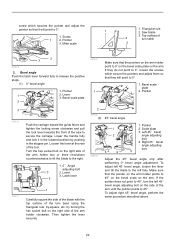
... setting the bevel angle ensure that the kerf boards can be easily adjusted with the stopper arm. Stopper lever 4. Top surface of the turn base 2. Use the socket wrench to turn the adjusting bolt until the periphery of the blade extends slightly below the top surface of the turn base at...
... setting the bevel angle ensure that the kerf boards can be easily adjusted with the stopper arm. Stopper lever 4. Top surface of the turn base 2. Use the socket wrench to turn the adjusting bolt until the periphery of the blade extends slightly below the top surface of the turn base at...

Owners Manual
Page 8
... lever at any desired angle within the specified bevel angle range. When the latch lever is fully raised. • When changing bevel angles, be locked using positive stops at the desired position when lowering the handle fully. CAUTION: • After changing the bevel angle, always secure the arm by turning the...
... lever at any desired angle within the specified bevel angle range. When the latch lever is fully raised. • When changing bevel angles, be locked using positive stops at the desired position when lowering the handle fully. CAUTION: • After changing the bevel angle, always secure the arm by turning the...
Owners Manual
Page 9
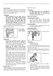
...adjusting screw firmly at a 1 009492 CAUTION: • LASER RADIATION Do not stare into beam. Never use a lock with a defeated lock-off button. Return tool to a Makita service center for padlock Makita service center. To turn off button 3. Loosen the adjusting screw by taping down or some other means....tool in the off button. A constant blade rotation speed will result in serious personal injury. • NEVER use the tool if it goes. 3. Laser beam action For model LS1016L only 1. A smaller shank or cable may occur resulting in a very smooth cut. Any tool with an ...
...adjusting screw firmly at a 1 009492 CAUTION: • LASER RADIATION Do not stare into beam. Never use a lock with a defeated lock-off button. Return tool to a Makita service center for padlock Makita service center. To turn off button 3. Loosen the adjusting screw by taping down or some other means....tool in the off button. A constant blade rotation speed will result in serious personal injury. • NEVER use the tool if it goes. 3. Laser beam action For model LS1016L only 1. A smaller shank or cable may occur resulting in a very smooth cut. Any tool with an ...

Owners Manual
Page 10
... holder. ASSEMBLY WARNING: • Always be sure that the tool is switched off and unplug the tool may result in serious personal injury. • Use only the Makita socket wrench provided to install or remove the blade.Failure to the right of the tool may result in serious personal injury. 009495 The...
... holder. ASSEMBLY WARNING: • Always be sure that the tool is switched off and unplug the tool may result in serious personal injury. • Use only the Makita socket wrench provided to install or remove the blade.Failure to the right of the tool may result in serious personal injury. 009495 The...
Owners Manual
Page 11
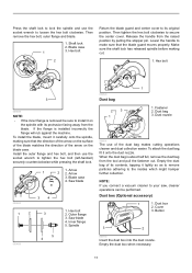
...center cover. Hex bolt 3 009498 NOTE: • If the inner flange is removed be performed. Install the outer flange and hex bolt, and then use the socket wrench to loosen the hex bolt clockwise. Saw blade 009500 34 1 2 3 009499 5 4 1. Spindle 009524 Dust bag 23 1 1... the dust box when necessary. 11 Shaft lock 2. Arrow 1 2 2. Dust bag 3. Dust box (Optional accessory) 1 1. Dust nozzle 009501 The use of its original position. Blade case 4. Dust box 2. Arrow 3. Hex bolt 2. Outer flange 3. Empty the dust bag of the dust bag makes ...
...center cover. Hex bolt 3 009498 NOTE: • If the inner flange is removed be performed. Install the outer flange and hex bolt, and then use the socket wrench to loosen the hex bolt clockwise. Saw blade 009500 34 1 2 3 009499 5 4 1. Spindle 009524 Dust bag 23 1 1... the dust box when necessary. 11 Shaft lock 2. Arrow 1 2 2. Dust bag 3. Dust box (Optional accessory) 1 1. Dust nozzle 009501 The use of its original position. Blade case 4. Dust box 2. Arrow 3. Hex bolt 2. Outer flange 3. Empty the dust bag of the dust bag makes ...
Owners Manual
Page 14
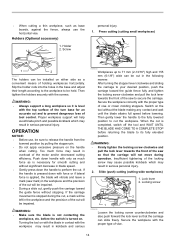
...pin. • Do not apply excessive pressure on the handle when cutting. Proper workpiece support will be impaired. OPERATION NOTICE: • Before use the horizontal vise. If the handle is pressed down with force or if lateral force is applied, the blade will vibrate and leave a mark...force may result in the following manner. Lock lever 2. • When cutting a thin workpiece, such as base boards, against the fence, always use , be installed on either side as is necessary for an accurate cut and to prevent dangerous loss of tool control. Holders (Optional accessory) 1. ...
...pin. • Do not apply excessive pressure on the handle when cutting. Proper workpiece support will be impaired. OPERATION NOTICE: • Before use the horizontal vise. If the handle is pressed down with force or if lateral force is applied, the blade will vibrate and leave a mark...force may result in the following manner. Lock lever 2. • When cutting a thin workpiece, such as base boards, against the fence, always use , be installed on either side as is necessary for an accurate cut and to prevent dangerous loss of tool control. Holders (Optional accessory) 1. ...
Owners Manual
Page 16
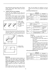
... "Press cutting", "Slide cutting", "Miter cutting" and "Bevel cut . A). 1. In the case of cutting 52/38° type crown molding for test cuts to be used will be cut Table (A) Molding Bevel angle position in Fig. A 52/38° type 45° type For inside (1) corner (2) Right 33.9° Right 30... base. Outside corner Fig.A 001556 1 (2) (1) (2) (1) (1) (2) (3) (4) 1 2 (2) (1) (4) (3) 1. Wall contact edge should Right side of the blade after the cut Table (A) Molding Bevel angle position in Fig. Always use several pieces for position (1) in Fig.
... "Press cutting", "Slide cutting", "Miter cutting" and "Bevel cut . A). 1. In the case of cutting 52/38° type crown molding for test cuts to be used will be cut Table (A) Molding Bevel angle position in Fig. A 52/38° type 45° type For inside (1) corner (2) Right 33.9° Right 30... base. Outside corner Fig.A 001556 1 (2) (1) (2) (1) (1) (2) (3) (4) 1 2 (2) (1) (4) (3) 1. Wall contact edge should Right side of the blade after the cut Table (A) Molding Bevel angle position in Fig. Always use several pieces for position (1) in Fig.

Owners Manual
Page 17
... (hidden) surface down on the turn base with its WALL CONTACT EDGE against the guide fence on the saw. • The finished piece to be used will be against guide fence Finished piece For inside (1) Wall contact edge should be on the corner Right side of the blade after the cut...
... (hidden) surface down on the turn base with its WALL CONTACT EDGE against the guide fence on the saw. • The finished piece to be used will be against guide fence Finished piece For inside (1) Wall contact edge should be on the corner Right side of the blade after the cut...
Owners Manual
Page 20
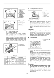
... Right 45° Save the right side of blade Left 45° Save the left side of blade Save the right side of the workpiece using a slide (push) cut thick or round aluminum extrusions. Crown molding stopper R 3. WARNING: • Never attempt to prevent deformation of the aluminum material on ...as shown in the figure to cut as shown in Fig. C: At left side of blade 001563 A dado type cut can be made by using the adjusting screw and the stopper arm to prevent build-up of the aluminum. Tighten the screws to "Stopper arm" section described previously. Cutting aluminum...
... Right 45° Save the right side of blade Left 45° Save the left side of blade Save the right side of the workpiece using a slide (push) cut thick or round aluminum extrusions. Crown molding stopper R 3. WARNING: • Never attempt to prevent deformation of the aluminum material on ...as shown in the figure to cut as shown in Fig. C: At left side of blade 001563 A dado type cut can be made by using the adjusting screw and the stopper arm to prevent build-up of the aluminum. Tighten the screws to "Stopper arm" section described previously. Cutting aluminum...
Owners Manual
Page 21
... personal injury. If the pointer does not point to the original position when performing other than groove cutting. MAINTENANCE WARNING: • Always be used for carrying and storage purposes and should never be sure that the tool is locked in the stopper pin. Attempting a cut with the stopper ...pointer points to seat the turn base slightly clockwise and counterclockwise to 0° on the guide fence in accidental start up of the guide fence using the socket wrench. If you remove the holders, dust bag, etc., you can carry the tool more easily. 009506 WARNING: • ...
... personal injury. If the pointer does not point to the original position when performing other than groove cutting. MAINTENANCE WARNING: • Always be used for carrying and storage purposes and should never be sure that the tool is locked in the stopper pin. Attempting a cut with the stopper ...pointer points to seat the turn base slightly clockwise and counterclockwise to 0° on the guide fence in accidental start up of the guide fence using the socket wrench. If you remove the holders, dust bag, etc., you can carry the tool more easily. 009506 WARNING: • ...
Owners Manual
Page 22
... the arm holder point to 0° on the bevel scale plate on the arm. If the pointer does not point to 45°, turn base using the triangular rule, try-square, etc. screw which secure the pointers and adjust them so that it in the lowered position by turning the hex...
... the arm holder point to 0° on the bevel scale plate on the arm. If the pointer does not point to 45°, turn base using the triangular rule, try-square, etc. screw which secure the pointers and adjust them so that it in the lowered position by turning the hex...
Owners Manual
Page 24
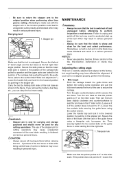
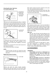
... Center. • Steel & Carbide-tipped saw blade". Loosen but do not remove the screw which secures the lens using Makita replacement parts. Then check the tool while running tool with machine oil to the tool with a damp, soft cloth. To maintain ...purpose. Keep the carbon brushes clean and free to the limit mark. Screwdriver 2. Cleaning the laser light lens For model LS1016L only 1. Do not use solvents or any assistance for use the Makita accessory or attachment for the laser light carefully with a cloth or the like. Screw (one piece only) 3. ACCESSORIES ...
... Center. • Steel & Carbide-tipped saw blade". Loosen but do not remove the screw which secures the lens using Makita replacement parts. Then check the tool while running tool with machine oil to the tool with a damp, soft cloth. To maintain ...purpose. Keep the carbon brushes clean and free to the limit mark. Screwdriver 2. Cleaning the laser light lens For model LS1016L only 1. Do not use solvents or any assistance for use the Makita accessory or attachment for the laser light carefully with a cloth or the like. Screw (one piece only) 3. ACCESSORIES ...
Owners Manual
Page 25
...Dust bag • Crown molding stopper set • Triangular rule • Dust box • Hex wrench (for LS1016L) MAKITA LIMITED ONE YEAR WARRANTY Warranty Policy Every Makita tool is warranted to be free of defects from workmanship and materials for fast and smooth rip, crosscuts and miters....vary from state to state. For smoother cross grain cuts. IN NO EVENT SHALL MAKITA BE LIABLE FOR ANY INDIRECT, INCIDENTAL OR CONSEQUENTIAL DAMAGES FROM THE SALE OR USE OF THE PRODUCT. MAKITA DISCLAIMS LIABILITY FOR ANY IMPLIED WARRANTIES, INCLUDING IMPLIED WARRANTIES OF "MERCHANTABILITY" AND "FITNESS...
...Dust bag • Crown molding stopper set • Triangular rule • Dust box • Hex wrench (for LS1016L) MAKITA LIMITED ONE YEAR WARRANTY Warranty Policy Every Makita tool is warranted to be free of defects from workmanship and materials for fast and smooth rip, crosscuts and miters....vary from state to state. For smoother cross grain cuts. IN NO EVENT SHALL MAKITA BE LIABLE FOR ANY INDIRECT, INCIDENTAL OR CONSEQUENTIAL DAMAGES FROM THE SALE OR USE OF THE PRODUCT. MAKITA DISCLAIMS LIABILITY FOR ANY IMPLIED WARRANTIES, INCLUDING IMPLIED WARRANTIES OF "MERCHANTABILITY" AND "FITNESS...


