User manual, English (US)
Page 3
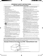
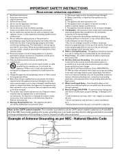
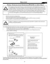
... use attachments/accessories specified by the manufacturer, or sold with a cart, stand, tripod, bracket, or table specified by the manufacturer. 12. The power supply cord or the plug has been damaged; B. Objects have fallen into the enclosure through openings. 22. Tilt/Stability - See Figure below. 21. Object and Liquid Entry - National Electric Code GROUND CLAMP ANTENNA...
... use attachments/accessories specified by the manufacturer, or sold with a cart, stand, tripod, bracket, or table specified by the manufacturer. 12. The power supply cord or the plug has been damaged; B. Objects have fallen into the enclosure through openings. 22. Tilt/Stability - See Figure below. 21. Object and Liquid Entry - National Electric Code GROUND CLAMP ANTENNA...

User manual, English (US)
Page 4
... (Monitor) Connection 15 AV Output 16 Install Menu Language Settings 17 Tuner Mode Control 18 Auto Program (Setting Up Channels 19 Channel Edit Control 20 Factory Reset 21 Smart Picture and Smart Sound Smart Picture Control 22 Smart Sound Control 22 Picture Menu TV Picture Menu Controls 23 Sound Menu TV Sound Menu Controls 24 Features Menu Auto Lock 25 Auto Lock Access Code 26 Auto Lock Program 27 Auto Lock - NOTE:This manual covers different versions and models. Audio/Video In Jacks: Use to quickly connect other Video Devices with Component Video Connectors 12 Digital TV...
... (Monitor) Connection 15 AV Output 16 Install Menu Language Settings 17 Tuner Mode Control 18 Auto Program (Setting Up Channels 19 Channel Edit Control 20 Factory Reset 21 Smart Picture and Smart Sound Smart Picture Control 22 Smart Sound Control 22 Picture Menu TV Picture Menu Controls 23 Sound Menu TV Sound Menu Controls 24 Features Menu Auto Lock 25 Auto Lock Access Code 26 Auto Lock Program 27 Auto Lock - NOTE:This manual covers different versions and models. Audio/Video In Jacks: Use to quickly connect other Video Devices with Component Video Connectors 12 Digital TV...

User manual, English (US)
Page 5
.../UHF antenna or cable 7 AC IN Connects the supplied AC power cord. 3 Headphones jack Connect to your headphones. 8 DVI IN (HDCP) Connect to your DVD player or other video equipment with 4 AV IN 3 Y, Pb, Pr Input jacks Connects to the component video connectors of your DVD player or other video equipments with DVI/HDCP output connectors. 9 PC IN Connect to your video and audio Connect to the Digital Satellite Receiver or other source of the LCD TV cabinet...
.../UHF antenna or cable 7 AC IN Connects the supplied AC power cord. 3 Headphones jack Connect to your headphones. 8 DVI IN (HDCP) Connect to your DVD player or other video equipment with 4 AV IN 3 Y, Pb, Pr Input jacks Connects to the component video connectors of your DVD player or other video equipments with DVI/HDCP output connectors. 9 PC IN Connect to your video and audio Connect to the Digital Satellite Receiver or other source of the LCD TV cabinet...
User manual, English (US)
Page 8
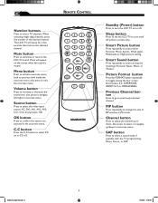
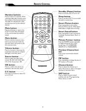
Number buttons Press to turn itself off . REMOTE CONTROL MENU OK SOURCE PIP CC Standby (Power) button Press to select TV channels. Channel button Press to adjust the channel up /down . The LCD TV will appear on or CC off within a certain time. Sleep button Press to set the LCD TV to the selected channel. SAP button Press to previously selected channel. Volume button Press to increase or decrease the sound level, also press to select or navigate up or down in...
Number buttons Press to turn itself off . REMOTE CONTROL MENU OK SOURCE PIP CC Standby (Power) button Press to select TV channels. Channel button Press to adjust the channel up /down . The LCD TV will appear on or CC off within a certain time. Sleep button Press to set the LCD TV to the selected channel. SAP button Press to previously selected channel. Volume button Press to increase or decrease the sound level, also press to select or navigate up or down in...
User manual, English (US)
Page 10
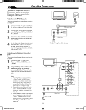
... coaxial cable to the TV jack (marked 75 Ω) on the rear of the LCD TV. 4 Set the Channel (or Output channel) switch of the Cable Box to watch Cable TV (your connections. Use the SOURCE button on the remote control to select AV 1 (or AV2, AV3, S-Video1, or S-Video2 if you have a Cable Box, follow either set of these steps to complete your Cable Box must be turned on). 2 CABLE IN OUTPUT CH 3 4 TO TV L R AUDIO OUT VIDEO OUT S VIDEO Cable Box Cable TV singal...
... coaxial cable to the TV jack (marked 75 Ω) on the rear of the LCD TV. 4 Set the Channel (or Output channel) switch of the Cable Box to watch Cable TV (your connections. Use the SOURCE button on the remote control to select AV 1 (or AV2, AV3, S-Video1, or S-Video2 if you have a Cable Box, follow either set of these steps to complete your Cable Box must be turned on). 2 CABLE IN OUTPUT CH 3 4 TO TV L R AUDIO OUT VIDEO OUT S VIDEO Cable Box Cable TV singal...

User manual, English (US)
Page 11
... weak signal mode via the smart picture settings in case your DVD Player is equipped with Component (Y, Pb, Pr) Output Jacks, please refer to "Connecting a DVD Player or other equipment, set the LCD TV to its AV mode. If Audio and Video is connected to Video (CVBS) input, you use of Component Video Connection for highest color and picture resolution in AV IN 2 and AV IN 3 located on the rear of the TV to these jacks.To view the material playing on...
... weak signal mode via the smart picture settings in case your DVD Player is equipped with Component (Y, Pb, Pr) Output Jacks, please refer to "Connecting a DVD Player or other equipment, set the LCD TV to its AV mode. If Audio and Video is connected to Video (CVBS) input, you use of Component Video Connection for highest color and picture resolution in AV IN 2 and AV IN 3 located on the rear of the TV to these jacks.To view the material playing on...

User manual, English (US)
Page 14
... products. 2. Proper working is only guaranteed with DVI connector 3 MENU OK SOURCE PIP CC DVI is not recommended to connect your HD device and to watch the programs. Note: 1. It is a specific digital input allowing encrypted transmission of your HD device (e.g. DVD player, Set Top Box..) to the DVI connector of the DVI IN connection. 2 Connect the AUDIO cable (if audio is gaining monumentum and quickly becoming an industry...
... products. 2. Proper working is only guaranteed with DVI connector 3 MENU OK SOURCE PIP CC DVI is not recommended to connect your HD device and to watch the programs. Note: 1. It is a specific digital input allowing encrypted transmission of your HD device (e.g. DVD player, Set Top Box..) to the DVI connector of the DVI IN connection. 2 Connect the AUDIO cable (if audio is gaining monumentum and quickly becoming an industry...

User manual, English (US)
Page 24
.... AVL (Auto Volume Leveler): When On, AVL will remain in Mono mode. • In case the sound from a VCR, DVD or other sound controls. 7 Press MENU MENU to remove the menu. 4 6 3 PIP 5 HELPFUL HINT • Treble and Bass can only be accessed when Smart Sound is set to see the menu. 2 Press the (CH-) AUDIO menu. OK 5 SOURCE Virtual Surround: Adds greater depth and dimension to highlight the MAIN CONTROL PICTURE AUDIO FEATURES INSTALL SMART SOUND...
.... AVL (Auto Volume Leveler): When On, AVL will remain in Mono mode. • In case the sound from a VCR, DVD or other sound controls. 7 Press MENU MENU to remove the menu. 4 6 3 PIP 5 HELPFUL HINT • Treble and Bass can only be accessed when Smart Sound is set to see the menu. 2 Press the (CH-) AUDIO menu. OK 5 SOURCE Virtual Surround: Adds greater depth and dimension to highlight the MAIN CONTROL PICTURE AUDIO FEATURES INSTALL SMART SOUND...
User manual, English (US)
Page 25
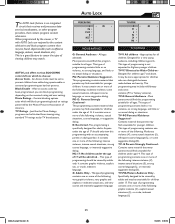
.... This is not expected to choose: Access Code - AUTO Lock offers various BLOCKING controls from which will be set to Older Children Designed for all children. This type of programming should only view this program suitable for children age 7 and above. Just like the Movie Ratings, programs can distinguish between make-believe and rearity. TV-PG Parental Guidance Suggested Contains material that contain...
.... This is not expected to choose: Access Code - AUTO Lock offers various BLOCKING controls from which will be set to Older Children Designed for all children. This type of programming should only view this program suitable for children age 7 and above. Just like the Movie Ratings, programs can distinguish between make-believe and rearity. TV-PG Parental Guidance Suggested Contains material that contain...

User manual, English (US)
Page 33
... watching. AVL (Auto Volume Leveler)- The AUDIO controls allow you to select from 3 factory-set controls (News, Music, and Theatre) enhance the particular program you are in volume occur during commercial breaks or channel changes. 5 Press the (VOL+) or (VOL-) buttons to adjust the item. 6 Press MENU MENU repeatedly to remove the menu from Stereo, Mono, and SAP. Stereo: To select from the screen. 1 6 MENU 3 OK SOURCE 5 CC 2 4 4 3 PIP 5 AUDIO SMART SOUND S E T T I N GS...
... watching. AVL (Auto Volume Leveler)- The AUDIO controls allow you to select from 3 factory-set controls (News, Music, and Theatre) enhance the particular program you are in volume occur during commercial breaks or channel changes. 5 Press the (VOL+) or (VOL-) buttons to adjust the item. 6 Press MENU MENU repeatedly to remove the menu from Stereo, Mono, and SAP. Stereo: To select from the screen. 1 6 MENU 3 OK SOURCE 5 CC 2 4 4 3 PIP 5 AUDIO SMART SOUND S E T T I N GS...
User manual, English (US)
Page 36
... sound in S-Video or Video (CVBS) mode. Connect the antenna or Cable TV signal securely to turn on the TV again. • Make sure the outlet is not on page 19. Only one of the two sound inputs can be heared in this LCD-TV set up all available channels. Details are on a wall switch. • Make sure a fuse has not blown at the power outlet. • Always point the remote control...
... sound in S-Video or Video (CVBS) mode. Connect the antenna or Cable TV signal securely to turn on the TV again. • Make sure the outlet is not on page 19. Only one of the two sound inputs can be heared in this LCD-TV set up all available channels. Details are on a wall switch. • Make sure a fuse has not blown at the power outlet. • Always point the remote control...
User manual, English
Page 3
... wire to an antenna discharge unit, size of grounding connectors, location of these instructions. 2. Servicing is required when the apparatus has been damaged in any way, such as power-supply cord or plug is provided to call the CATV system installer's attention to Article 82040 of the NEC that provides guidelines for a long time. Disposal of antenna-discharge unit, connection to the CATV...
... wire to an antenna discharge unit, size of grounding connectors, location of these instructions. 2. Servicing is required when the apparatus has been damaged in any way, such as power-supply cord or plug is provided to call the CATV system installer's attention to Article 82040 of the NEC that provides guidelines for a long time. Disposal of antenna-discharge unit, connection to the CATV...

User manual, English
Page 4
...children viewing inappropriate material. NOTE:This manual covers different versions and models. Audio/Video In Jacks: Use to quickly connect other Video Devices with Component Video Connectors 12 Digital TV Receiver, or a Digital Satellite Receiver with HD (High Definition) Output 13 Digital Satellite Receiver with DVI connector 14 PC (Monitor) Connection 15 AV Output 16 Install Menu Language Settings 17 Tuner Mode Control 18 Auto Program (Setting Up Channels 19 Channel Edit Control 20 Factory Reset 21 Smart Picture and Smart Sound Smart Picture Control 22 Smart Sound Control...
...children viewing inappropriate material. NOTE:This manual covers different versions and models. Audio/Video In Jacks: Use to quickly connect other Video Devices with Component Video Connectors 12 Digital TV Receiver, or a Digital Satellite Receiver with HD (High Definition) Output 13 Digital Satellite Receiver with DVI connector 14 PC (Monitor) Connection 15 AV Output 16 Install Menu Language Settings 17 Tuner Mode Control 18 Auto Program (Setting Up Channels 19 Channel Edit Control 20 Factory Reset 21 Smart Picture and Smart Sound Smart Picture Control 22 Smart Sound Control...

User manual, English
Page 5
... Definition) video equipment. SD (Standard Definition) video format. 10 HD (High Definition) IN 5 AV OUT Connects to the input jacks of heat. .Do not place the LCD TV where it can be exposed to the Digital Satellite Receiver or other source of your video and audio Connect to rain or excessive moisture. Be sure the surface is displaying CVBS or RF signals.
... Definition) video equipment. SD (Standard Definition) video format. 10 HD (High Definition) IN 5 AV OUT Connects to the input jacks of heat. .Do not place the LCD TV where it can be exposed to the Digital Satellite Receiver or other source of your video and audio Connect to rain or excessive moisture. Be sure the surface is displaying CVBS or RF signals.
User manual, English
Page 8
Volume button Press to increase or decrease the sound level, also press to turn itself off . MENU OK SOURCE PIP CC Standby (Power) button Press to navigate left/right in PC mode. Smart Sound button Press repeatedly to select TV channels. REMOTE CONTROL Number buttons Press to select among the four screen format sizes; 4:3, SUPERWIDE, ZOOM 16:9 or WIDESCREEN. When selecting single-digit channels, press the number of PIP window in onscreen menu. Menu button Press to activate onscreen menu, back...
Volume button Press to increase or decrease the sound level, also press to turn itself off . MENU OK SOURCE PIP CC Standby (Power) button Press to navigate left/right in PC mode. Smart Sound button Press repeatedly to select TV channels. REMOTE CONTROL Number buttons Press to select among the four screen format sizes; 4:3, SUPERWIDE, ZOOM 16:9 or WIDESCREEN. When selecting single-digit channels, press the number of PIP window in onscreen menu. Menu button Press to activate onscreen menu, back...

User manual, English
Page 11
... color and picture resolution in AV IN 2 and AV IN 3 located on the rear of other equipment. If your VCR equipped with A/V connectors 2 MENU OK SOURCE PIP CC HELPFUL HINT • The Audio jack of noise or strange patterns during play mode. 11 Connect a DVD player,VCR Video Game, Camcorder, etc., to these jacks.To view the material playing on the remote control to Video (CVBS) input, you use of Component Video Connection for this hookup) to the TV's S-Video...
... color and picture resolution in AV IN 2 and AV IN 3 located on the rear of other equipment. If your VCR equipped with A/V connectors 2 MENU OK SOURCE PIP CC HELPFUL HINT • The Audio jack of noise or strange patterns during play mode. 11 Connect a DVD player,VCR Video Game, Camcorder, etc., to these jacks.To view the material playing on the remote control to Video (CVBS) input, you use of Component Video Connection for this hookup) to the TV's S-Video...

User manual, English
Page 14
... the DVI IN connection. 3 Use Source button on the remote control to select DVI to properly display. 3. DVD player, Set Top Box..) to the DVI connector of the DVI IN connection. 2 Connect the AUDIO cable (if audio is gaining monumentum and quickly becoming an industry standard for the television to watch the programs. Note: 1. DVI is present) to the Audio outputs of your PC to LCD TV via DVI connection, since the LCD TV may cause...
... the DVI IN connection. 3 Use Source button on the remote control to select DVI to properly display. 3. DVD player, Set Top Box..) to the DVI connector of the DVI IN connection. 2 Connect the AUDIO cable (if audio is gaining monumentum and quickly becoming an industry standard for the television to watch the programs. Note: 1. DVI is present) to the Audio outputs of your PC to LCD TV via DVI connection, since the LCD TV may cause...

User manual, English
Page 33
... standby mode. MAIN CONTROL PICTURE AUDIO FEATURES INSTALL SMART SOUND S E T T I N GS STEREO VIRTUAL SURROUND AVL YES HELPFUL HINT To adjust other items repeat steps 4 and 5. 33 The 3 factory-set controls (News, Music, and Theatre) enhance the particular program you to select from 3 factory-set controls and a personal control. The AUDIO controls allow you are in volume occur during commercial breaks or channel changes. 5 Press the (VOL+) or (VOL-) buttons to adjust the item. 6 Press MENU MENU...
... standby mode. MAIN CONTROL PICTURE AUDIO FEATURES INSTALL SMART SOUND S E T T I N GS STEREO VIRTUAL SURROUND AVL YES HELPFUL HINT To adjust other items repeat steps 4 and 5. 33 The 3 factory-set controls (News, Music, and Theatre) enhance the particular program you to select from 3 factory-set controls and a personal control. The AUDIO controls allow you are in volume occur during commercial breaks or channel changes. 5 Press the (VOL+) or (VOL-) buttons to adjust the item. 6 Press MENU MENU...

User manual, English
Page 39
... not installed and used with ferrite core part number is 3138 198 71441. • If your RF shield cable without ferrite core, you can be utilized when "non-ferrited" video cables are designed to provide reasonable protection against harmful interference in a residential installation. Cable tie 5. Locate the video connector that goes to the video connector as possible, as close to the computer and plugs...
... not installed and used with ferrite core part number is 3138 198 71441. • If your RF shield cable without ferrite core, you can be utilized when "non-ferrited" video cables are designed to provide reasonable protection against harmful interference in a residential installation. Cable tie 5. Locate the video connector that goes to the video connector as possible, as close to the computer and plugs...
User manual, Spanish
Page 39
Open the ferrite core. 2. Locate the video connector that to which the receiver is connected. • Consult the dealer or an experienced radio/TV technician for compliance could void the user's authority to operate the equipment. Lock the ferrite core. 4. Place two cable tie wrap on a circuit different from Philips Factory Service Center, installation as shown in a residential installation. This kit must be determined...
Open the ferrite core. 2. Locate the video connector that to which the receiver is connected. • Consult the dealer or an experienced radio/TV technician for compliance could void the user's authority to operate the equipment. Lock the ferrite core. 4. Place two cable tie wrap on a circuit different from Philips Factory Service Center, installation as shown in a residential installation. This kit must be determined...


