

User Manual
Page 13
... 2 Quick Start ...3 Preparing Tools and Components 3 Installing a Processor 4 Installing DDR4 memory 5 Connecting the Front Panel Header 6 Installing the Motherboard 7 Installing SATA Drives 8 Installing a Graphics Card 9 Connecting Peripheral Devices 10 Connecting the Power Connectors 11 Power On...12 Specifications...15 Rear I/O Panel ...21 LAN Port LED Status Table 21 Audio Ports Configuration 21 Realtek HD Audio Manager 22 Overview of Components 24 Component Contents 25 CPU Socket ...26 DIMM Slots...27 PCI_E1~5: PCIe Expansion Slots 29 PCIe x16 slots bandwidth table...
... 2 Quick Start ...3 Preparing Tools and Components 3 Installing a Processor 4 Installing DDR4 memory 5 Connecting the Front Panel Header 6 Installing the Motherboard 7 Installing SATA Drives 8 Installing a Graphics Card 9 Connecting Peripheral Devices 10 Connecting the Power Connectors 11 Power On...12 Specifications...15 Rear I/O Panel ...21 LAN Port LED Status Table 21 Audio Ports Configuration 21 Realtek HD Audio Manager 22 Overview of Components 24 Component Contents 25 CPU Socket ...26 DIMM Slots...27 PCI_E1~5: PCIe Expansion Slots 29 PCIe x16 slots bandwidth table...

User Manual
Page 14
... Boot...61 Security ...61 Save & Exit...62 OC...63 M-FLASH ...72 OC PROFILE ...73 HARDWARE MONITOR 74 Software Description 75 Installing Windows® 7/ 8.1/ 10 75 Installing Drivers 75 Installing Utilities 75 COMMAND CENTER 76 LIVE UPDATE 6...80 SHORTCUT MANAGER 82 MYSTIC LIGHT...84 M-CLOUD ...85 RAMDISK...88 USB SPEED UP ...89 Intel® Extreme Tuning Utility 90 RAID Configuration 91 Using Intel® Rapid Storage Technology Option ROM 91 Degraded RAID Array 94 Troubleshooting...
... Boot...61 Security ...61 Save & Exit...62 OC...63 M-FLASH ...72 OC PROFILE ...73 HARDWARE MONITOR 74 Software Description 75 Installing Windows® 7/ 8.1/ 10 75 Installing Drivers 75 Installing Utilities 75 COMMAND CENTER 76 LIVE UPDATE 6...80 SHORTCUT MANAGER 82 MYSTIC LIGHT...84 M-CLOUD ...85 RAMDISK...88 USB SPEED UP ...89 Intel® Extreme Tuning Utility 90 RAID Configuration 91 Using Intel® Rapid Storage Technology Option ROM 91 Degraded RAID Array 94 Troubleshooting...

User Manual
Page 16
Storage Audio LAN Back Panel Connectors Continued from previous page Intel® X99 Chipset y 10x SATA 6Gb/s ports (2 ports from SATAe port) ƒ SATA1~6 support RAID 0, RAID 1, RAID 5 and RAID 10 ƒ SATA7~10 only support IDE mode and AHCI mode y 1x M.2 slot (Key M) ƒ For 40-lanes CPU, it supports up to PCIe 3.0 x4 and SATA 6Gb/s ƒ For 28-lanes CPU, it supports up to PCIe 2.0 x2 and SATA 6Gb/s ƒ Supports 2242/ 2260/ 2280/ 22110 storage devices y 1x U.2 port ƒ Supports PCIe 3.0 x4 NVMe storage y 1x...
Storage Audio LAN Back Panel Connectors Continued from previous page Intel® X99 Chipset y 10x SATA 6Gb/s ports (2 ports from SATAe port) ƒ SATA1~6 support RAID 0, RAID 1, RAID 5 and RAID 10 ƒ SATA7~10 only support IDE mode and AHCI mode y 1x M.2 slot (Key M) ƒ For 40-lanes CPU, it supports up to PCIe 3.0 x4 and SATA 6Gb/s ƒ For 28-lanes CPU, it supports up to PCIe 2.0 x2 and SATA 6Gb/s ƒ Supports 2242/ 2260/ 2280/ 22110 storage devices y 1x U.2 port ƒ Supports PCIe 3.0 x4 NVMe storage y 1x...
User Manual
Page 18
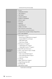
... BOOST Support ƒ Quad-Channel DDR4 Memory Support ƒ Isolated DDR4 Circuit Design ƒ DDR4 XMP Ready ƒ Steel Armor Ready y PCI Express 3.0 Support ƒ 3-Way Nvidia SLITM Support ƒ 3-Way AMD CrossFireTM Support y Multi-GPU with Steel Armor y USB 3.1 Gen2 Type-A/ Type-C Ready y Turbo M.2 Ready ƒ PCIe 3.0 x4 (32 Gb/s) Support ƒ PCIe/ SATA Dual Mode Support ƒ Steel Armor Ready y U.2 Ready y NVMe / AHCI Driver Support y 2-Digit Debug Code LED y EZ Debug LED y RGB LED pin header Continued...
... BOOST Support ƒ Quad-Channel DDR4 Memory Support ƒ Isolated DDR4 Circuit Design ƒ DDR4 XMP Ready ƒ Steel Armor Ready y PCI Express 3.0 Support ƒ 3-Way Nvidia SLITM Support ƒ 3-Way AMD CrossFireTM Support y Multi-GPU with Steel Armor y USB 3.1 Gen2 Type-A/ Type-C Ready y Turbo M.2 Ready ƒ PCIe 3.0 x4 (32 Gb/s) Support ƒ PCIe/ SATA Dual Mode Support ƒ Steel Armor Ready y U.2 Ready y NVMe / AHCI Driver Support y 2-Digit Debug Code LED y EZ Debug LED y RGB LED pin header Continued...

User Manual
Page 47
... Mode (SMM) initialization 37 Post-Memory System Agent initialization is started 1A - 1C Pre-memory PCH initialization (PCH module specific) 2B Memory initialization. Debug Code LED The Debug Code LED displays progress and error codes during and after microcode loading 0B Cache initialization SEC Error Codes 0C - 0D Reserved for details. system setup, pre-OS user interface & selecting a bootable device (CD/DVD, HDD, USB, Network, Shell, ...) Debug Code LED Table SEC Progress Codes 01 Power on. Cache initialization CPU post-memory...
... Mode (SMM) initialization 37 Post-Memory System Agent initialization is started 1A - 1C Pre-memory PCH initialization (PCH module specific) 2B Memory initialization. Debug Code LED The Debug Code LED displays progress and error codes during and after microcode loading 0B Cache initialization SEC Error Codes 0C - 0D Reserved for details. system setup, pre-OS user interface & selecting a bootable device (CD/DVD, HDD, USB, Network, Shell, ...) Debug Code LED Table SEC Progress Codes 01 Power on. Cache initialization CPU post-memory...

User Manual
Page 48
... started 3C - 3E Post-Memory PCH initialization (PCH module specific) 4F DXE IPL is started A5 SCSI Reset A6 SCSI Detect A7 SCSI Enable A8 Setup Verifying Password A9 Start of Setup AB Setup Input Wait AD Ready To Boot event AE Legacy Boot event AF Exit Boot Services event B0 Runtime Set Virtual Address MAP Begin B1 Runtime Set Virtual Address MAP End B2 Legacy Option ROM Initialization B3 System Reset B4 USB hot plug B5 PCI bus...
... started 3C - 3E Post-Memory PCH initialization (PCH module specific) 4F DXE IPL is started A5 SCSI Reset A6 SCSI Detect A7 SCSI Enable A8 Setup Verifying Password A9 Start of Setup AB Setup Input Wait AD Ready To Boot event AE Legacy Boot event AF Exit Boot Services event B0 Runtime Set Virtual Address MAP Begin B1 Runtime Set Virtual Address MAP End B2 Legacy Option ROM Initialization B3 System Reset B4 USB hot plug B5 PCI bus...

User Manual
Page 49
... password D9 Error loading Boot Option (LoadImage returned error) DA Boot Option is failed (StartImage returned error) DB Flash update is failed DC Reset protocol is not available S3 Resume Progress Codes E0 S3 Resume is stared (S3 Resume PPI is waking up from the S3 sleep state 40 System is called by user (Forced recovery) F2 Recovery process started F3 F4 F5 - FF Reserved for future AMI codes DXE Error Codes...
... password D9 Error loading Boot Option (LoadImage returned error) DA Boot Option is failed (StartImage returned error) DB Flash update is failed DC Reset protocol is not available S3 Resume Progress Codes E0 S3 Resume is stared (S3 Resume PPI is waking up from the S3 sleep state 40 System is called by user (Forced recovery) F2 Recovery process started F3 F4 F5 - FF Reserved for future AMI codes DXE Error Codes...

User Manual
Page 51
... your motherboard model from MSI website. Updating the BIOS with M-FLASH Before updating: Please download the latest BIOS file that contains the update file into the USB flash drive. Check MB BIOS box and click on the motherboard. Install and launch MSI LIVE UPDATE 6. 2. BIOS Setup 51 y Short the Clear CMOS jumper on Scan button. 4. Press Del key to perform the BIOS update process. 5. Click Next and choose In Windows mode. Select Manual scan. 3. Resetting BIOS You might need to restore the default BIOS setting to solve certain problems...
... your motherboard model from MSI website. Updating the BIOS with M-FLASH Before updating: Please download the latest BIOS file that contains the update file into the USB flash drive. Check MB BIOS box and click on the motherboard. Install and launch MSI LIVE UPDATE 6. 2. BIOS Setup 51 y Short the Clear CMOS jumper on Scan button. 4. Press Del key to perform the BIOS update process. 5. Click Next and choose In Windows mode. Select Manual scan. 3. Resetting BIOS You might need to restore the default BIOS setting to solve certain problems...

User Manual
Page 52
...is installed. 52 BIOS Setup y M-Flash - shows the CPU/ DDR speed, CPU/ MB temperature, MB/ CPU type, memory size, CPU/ DDR voltage, BIOS version and build date. enable or disable the LAN Option ROM, Fast Boot, HD audio controller, IDE, AHCI, RAID, CPU Fan Fail Warning Control and BIOS Log Review by pressing the Setup Mode switch or F7 function key. y Hardware Monitor - allows you to manually control the fan speed by percentage. press this button to display the Hardware Monitor menu that provides the way to update BIOS with a USB flash drive. EZ Mode At EZ mode, it to USB flash...
...is installed. 52 BIOS Setup y M-Flash - shows the CPU/ DDR speed, CPU/ MB temperature, MB/ CPU type, memory size, CPU/ DDR voltage, BIOS version and build date. enable or disable the LAN Option ROM, Fast Boot, HD audio controller, IDE, AHCI, RAID, CPU Fan Fail Warning Control and BIOS Log Review by pressing the Setup Mode switch or F7 function key. y Hardware Monitor - allows you to manually control the fan speed by percentage. press this button to display the Hardware Monitor menu that provides the way to update BIOS with a USB flash drive. EZ Mode At EZ mode, it to USB flash...

User Manual
Page 56
...as LAN, HDD, USB and audio. It is enabled. [Enabled] Enables the onboard LAN Boot ROM. [Disabled] Disables the onboard LAN Boot ROM. Press Enter to enter the sub-menu. fNetwork Stack [Disabled] Sets UEFI network stack for detailed settings. fPEG X - This item appears when installing 28-lanes CPU. fOnboard LAN Controller [Enabled] Enables or disables the onboard LAN controller. fAbove 4G Decoding [Disabled] Enables or disables 64-bit capable devices to be managed by BIOS. [Gen1] Enables PCIe Gen1 support only. [Gen2] Enables PCIe Gen2 support only. [Gen3] Enables PCIe Gen3...
...as LAN, HDD, USB and audio. It is enabled. [Enabled] Enables the onboard LAN Boot ROM. [Disabled] Disables the onboard LAN Boot ROM. Press Enter to enter the sub-menu. fNetwork Stack [Disabled] Sets UEFI network stack for detailed settings. fPEG X - This item appears when installing 28-lanes CPU. fOnboard LAN Controller [Enabled] Enables or disables the onboard LAN controller. fAbove 4G Decoding [Disabled] Enables or disables 64-bit capable devices to be managed by BIOS. [Gen1] Enables PCIe Gen1 support only. [Gen2] Enables PCIe Gen2 support only. [Gen3] Enables PCIe Gen3...

User Manual
Page 57
... Audio Controller [Enabled] Enables or disables the onboard High Definition Audio controller. Press Enter to enable or disable the SATA hot plug support. [Enabled] Enables hot plug support for the SATA ports. [Disabled] Disables hot plug support for SATA storage devices. BIOS Setup 57 fsSATA Mode [AHCI Mode] (For SATA7~10) Sets the operation mode of the onboard SATA controller. [IDE] Specify the IDE mode for SATA storage devices. [AHCI Mode] Specify the AHCI mode for the operating system without XHCI hand-off feature. f USB Configuration Sets the onboard USB...
... Audio Controller [Enabled] Enables or disables the onboard High Definition Audio controller. Press Enter to enable or disable the SATA hot plug support. [Enabled] Enables hot plug support for the SATA ports. [Disabled] Disables hot plug support for SATA storage devices. BIOS Setup 57 fsSATA Mode [AHCI Mode] (For SATA7~10) Sets the operation mode of the onboard SATA controller. [IDE] Specify the IDE mode for SATA storage devices. [AHCI Mode] Specify the AHCI mode for the operating system without XHCI hand-off feature. f USB Configuration Sets the onboard USB...

User Manual
Page 58
... the system to enter the sub-menu. f Power Management Setup Sets system Power Management of power, reset, PCH, audio LEDs. fRestore after AC Power Loss [Power Off] Sets the system behaviors while encountering the AC power loss. [Power Off] Leaves the system in power off state after restoring AC power. [Power On] Boot up by USB, PCI and PCIe devices. [Disabled] Disables this function. 58 BIOS Setup fWindows 8.1/ 10 WHQL Support [Disabled] Enables the supports for Windows 8.1/ 10 or disables for the operating...
... the system to enter the sub-menu. f Power Management Setup Sets system Power Management of power, reset, PCH, audio LEDs. fRestore after AC Power Loss [Power Off] Sets the system behaviors while encountering the AC power loss. [Power Off] Leaves the system in power off state after restoring AC power. [Power On] Boot up by USB, PCI and PCIe devices. [Disabled] Disables this function. 58 BIOS Setup fWindows 8.1/ 10 WHQL Support [Disabled] Enables the supports for Windows 8.1/ 10 or disables for the operating...

User Manual
Page 60
... PS/2 Mouse [Disabled] Enables or disables the system wake up function of installed PCI-E expansion cards, integrated LAN controllers or USB devices which are supported by third party integrated chips. [Enabled] Enables the system to be awakened from the power saving modes when activity or input signal of PCIe device is detected. [Disabled] Disables this function. fResume From S3/S4/S5 by PS/2 Keyboard [Disabled] Enables or disables the system wake up by Onboard Intel LAN. [Enabled] Enables the system...
... PS/2 Mouse [Disabled] Enables or disables the system wake up function of installed PCI-E expansion cards, integrated LAN controllers or USB devices which are supported by third party integrated chips. [Enabled] Enables the system to be awakened from the power saving modes when activity or input signal of PCIe device is detected. [Disabled] Disables this function. fResume From S3/S4/S5 by PS/2 Keyboard [Disabled] Enables or disables the system wake up by Onboard Intel LAN. [Enabled] Enables the system...

User Manual
Page 61
... used to show "Installed". Security f Administrator Password Sets administrator password for system boot. BIOS Setup 61 f Intel ( R ) Ethernet Connection I218-(MAC Shows driver information and configuration of system boot devices. f Full Screen Logo Display [Enabled] Enables or disables to prioritize the installed boot devices. After setting the user password, the state of the ethernet controller parameter. f Intel ( R ) Ethernet Connection I210-(MAC Shows driver information and configuration of this item will be configured automatically by long pressing the power button...
... used to show "Installed". Security f Administrator Password Sets administrator password for system boot. BIOS Setup 61 f Intel ( R ) Ethernet Connection I218-(MAC Shows driver information and configuration of system boot devices. f Full Screen Logo Display [Enabled] Enables or disables to prioritize the installed boot devices. After setting the user password, the state of the ethernet controller parameter. f Intel ( R ) Ethernet Connection I210-(MAC Shows driver information and configuration of this item will be configured automatically by long pressing the power button...

User Manual
Page 65
... after changing memory timing. f CPU Base Clock Apply Mode [Auto]* Sets the applying mode for CPU. Please note the overclocking behavior is installed. This item appears when the installed CPU supports this adjustment is not guaranteed. f Memory Try It ! [Disabled] It improve memory compatibility or performance by memory module. f DRAM Frequency [Auto] Sets the DRAM frequency. f Advanced DRAM Configuration Press Enter to configure the DRAM timing for each/ all memory channel. [UnLink] Allows user to enter the sub-menu. f Filter PLL [Auto] Enables or disables...
... after changing memory timing. f CPU Base Clock Apply Mode [Auto]* Sets the applying mode for CPU. Please note the overclocking behavior is installed. This item appears when the installed CPU supports this adjustment is not guaranteed. f Memory Try It ! [Disabled] It improve memory compatibility or performance by memory module. f DRAM Frequency [Auto] Sets the DRAM frequency. f Advanced DRAM Configuration Press Enter to configure the DRAM timing for each/ all memory channel. [UnLink] Allows user to enter the sub-menu. f Filter PLL [Auto] Enables or disables...

User Manual
Page 68
f DRAM Voltages control [Auto] These options allows you to set the voltages related to enter the sub-menu. You can set it manually. fCPU Technology Support Press Enter to memory. fDIMMx Memory SPD Press Enter to CPU. In this item if the system does not support HT function. f CPU Voltages control [Auto] These options allows you to set the voltages related to enter the sub-menu. f CPU Features Press Enter to select the number of active CPU cores. 68 BIOS Setup fActive Processor Cores Control [Disabled] Allows you to...
f DRAM Voltages control [Auto] These options allows you to set the voltages related to enter the sub-menu. You can set it manually. fCPU Technology Support Press Enter to memory. fDIMMx Memory SPD Press Enter to CPU. In this item if the system does not support HT function. f CPU Voltages control [Auto] These options allows you to set the voltages related to enter the sub-menu. f CPU Features Press Enter to select the number of active CPU cores. 68 BIOS Setup fActive Processor Cores Control [Disabled] Allows you to...

User Manual
Page 70
... specification when system request the highest performance state. [Disabled] Disables this function. This item willappear when Simple/ Advanced Mode is installed. [Enabled] Enables this function to reduce the CPU frequency and voltage for CPU in halt state. [Disabled] Disables this function. fShort Duration Power Limit (W) [Auto] Sets the short duration TDP power limit for power-saving in Turbo Boost mode. 70 BIOS Setup This item is for Simple mode and appears when a CPU that support...
... specification when system request the highest performance state. [Disabled] Disables this function. This item willappear when Simple/ Advanced Mode is installed. [Enabled] Enables this function to reduce the CPU frequency and voltage for CPU in halt state. [Disabled] Disables this function. fShort Duration Power Limit (W) [Auto] Sets the short duration TDP power limit for power-saving in Turbo Boost mode. 70 BIOS Setup This item is for Simple mode and appears when a CPU that support...

User Manual
Page 75
... install utilities, you want to plug in Windows® 7/ 8.1/ 10. 2. Click OK button to finish. 7. Power on the computer. 2. Note: It is suggested to install. 5. Software Description Installing Windows® 7/ 8.1/ 10 1. Press any key when screen shows Press any key to the leftmost USB port when installing Windows® 7. 5. message. 7. Insert the Windows® 7/ 8.1/ 10 disc into your USB Keyboard/ USB Mouse to boot from the Boot Menu. 6. Click Install button. 6. Select the utilities you must complete drivers installation. 1. Start...
... install utilities, you want to plug in Windows® 7/ 8.1/ 10. 2. Click OK button to finish. 7. Power on the computer. 2. Note: It is suggested to install. 5. Software Description Installing Windows® 7/ 8.1/ 10 1. Press any key when screen shows Press any key to the leftmost USB port when installing Windows® 7. 5. message. 7. Insert the Windows® 7/ 8.1/ 10 disc into your USB Keyboard/ USB Mouse to boot from the Boot Menu. 6. Click Install button. 6. Select the utilities you must complete drivers installation. 1. Start...

User Manual
Page 96
... LAN port LEDs are heard, remove and reinstall the graphics card and then restart the computer. y Verify your got similar symptoms as mentioned below. The power is not working LAN cable. y If 1 long 2 short beeps are properly illuminated. y Remove secondary speakers/ headphones, HDMI cables, USB audio devices. y Check if all ATX power connectors like JPWR1~2 is connected to an electrical outlet securely. y Test with another known working graphics card. y Restart or reset your USB drive driver has been installed. y Check if the power switch cable...
... LAN port LEDs are heard, remove and reinstall the graphics card and then restart the computer. y Verify your got similar symptoms as mentioned below. The power is not working LAN cable. y If 1 long 2 short beeps are properly illuminated. y Remove secondary speakers/ headphones, HDMI cables, USB audio devices. y Check if all ATX power connectors like JPWR1~2 is connected to an electrical outlet securely. y Test with another known working graphics card. y Restart or reset your USB drive driver has been installed. y Check if the power switch cable...

User Manual
Page 100
... given as to make changes without notice. Version 1.4, 2016/10, update release for X99A WORKSTATION. Our products are acknowledged. Technical Support If a problem arises with your system and no solution can be obtained from the user guide, please contact your product at: http://register.msi.com Trademark Recognition All product names used in the preparation of this manual are the properties of...
... given as to make changes without notice. Version 1.4, 2016/10, update release for X99A WORKSTATION. Our products are acknowledged. Technical Support If a problem arises with your system and no solution can be obtained from the user guide, please contact your product at: http://register.msi.com Trademark Recognition All product names used in the preparation of this manual are the properties of...


