
User Guide
Page 2
... Technical Support If a problem arises with your system and no guarantee is a registered trademark of its contents. AMD, Athlon™, Athlon™ XP, Thoroughbred™, and Duron™ are registered trademarks of American Megatrends Inc. Award® is a registered trademark of Intel Corporation. Alternatively, please try the following help resources for FAQ, technical guide, BIOS updates, driver updates, and...
... Technical Support If a problem arises with your system and no guarantee is a registered trademark of its contents. AMD, Athlon™, Athlon™ XP, Thoroughbred™, and Duron™ are registered trademarks of American Megatrends Inc. Award® is a registered trademark of Intel Corporation. Alternatively, please try the following help resources for FAQ, technical guide, BIOS updates, driver updates, and...

User Guide
Page 8
... CPU 2-3 CPU & Cooler Installation 2-4 Dual Channel Memory Population Rules 2-7 Memory ...2-7 Installing DDRII Modules 2-8 Power Supply ...2-8 ATX 24-Pin Power Connector: ATXPWR1 2-9 ATX 12V Power Connector: JPW 1 2-9 Back Panel ...2-11 Floppy Disk Drive Connector: FDD1 2-12 Hard Disk Connector: IDE1 2-12 Connectors ...2-12 Serial ATAII Connectors: SATA1/2/3/4/7 2-13 Fan Power Connectors: CPUFAN1, NBFAN1, SYSFAN1 2-14 Chassis Intrusion Switch Connector: JCASE1 2-14 SPDIF-Out Connector: JSPD1 (Optional, for HDMI graphics card only) 2-15 CD-In Connector: CD_IN1 2-15 Front Panel Audio...
... CPU 2-3 CPU & Cooler Installation 2-4 Dual Channel Memory Population Rules 2-7 Memory ...2-7 Installing DDRII Modules 2-8 Power Supply ...2-8 ATX 24-Pin Power Connector: ATXPWR1 2-9 ATX 12V Power Connector: JPW 1 2-9 Back Panel ...2-11 Floppy Disk Drive Connector: FDD1 2-12 Hard Disk Connector: IDE1 2-12 Connectors ...2-12 Serial ATAII Connectors: SATA1/2/3/4/7 2-13 Fan Power Connectors: CPUFAN1, NBFAN1, SYSFAN1 2-14 Chassis Intrusion Switch Connector: JCASE1 2-14 SPDIF-Out Connector: JSPD1 (Optional, for HDMI graphics card only) 2-15 CD-In Connector: CD_IN1 2-15 Front Panel Audio...
User Guide
Page 9
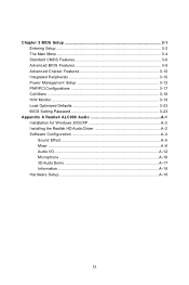
... 3 BIOS Setup 3-1 Entering Setup ...3-2 The Main Menu ...3-4 Standard CMOS Features 3-6 Advanced BIOS Features 3-8 Advanced Chipset Features 3-10 Integrated Peripherals 3-10 Power Management Setup 3-12 PNP/PCI Configurations 3-17 Cell Menu ...3-18 H/W Monitor ...3-19 Load Optimized Defaults 3-23 BIOS Setting Password 3-23 Appendix A Realtek ALC888 Audio A-1 Installation for W indows 2000/XP A-2 Installing the Realtek HD Audio Driver A-2 Software Configuration A-4 Sound Effect A-5 Mixer ...A-8 Audio I/O ...A-12 Microphone A-16 3D Audio Demo A-17 Information A-18 Hardware Setup...
... 3 BIOS Setup 3-1 Entering Setup ...3-2 The Main Menu ...3-4 Standard CMOS Features 3-6 Advanced BIOS Features 3-8 Advanced Chipset Features 3-10 Integrated Peripherals 3-10 Power Management Setup 3-12 PNP/PCI Configurations 3-17 Cell Menu ...3-18 H/W Monitor ...3-19 Load Optimized Defaults 3-23 BIOS Setting Password 3-23 Appendix A Realtek ALC888 Audio A-1 Installation for W indows 2000/XP A-2 Installing the Realtek HD Audio Driver A-2 Software Configuration A-4 Sound Effect A-5 Mixer ...A-8 Audio I/O ...A-12 Microphone A-16 3D Audio Demo A-17 Information A-18 Hardware Setup...

User Guide
Page 11
....php) LAN - Supports PCI LAN 10/100/1000 Fast Ethernet by Marvell 88SE6111 - North Bridge: Intel® P965/ G965 chipset - Flexible 8-channel audio with Fan Speed Control - Supports PIO, Bus Master operation mode SATA - 4 SATA II ports by ICH8 - 1 SATA II port by Realtek 8110SC Audio - Chip integrated by VIA VT6308, front x 1, real x 1 Floppy - 1 floppy port - Supports storage and data transfers at up to 300 MB/s 1394 (optional) - 2 1394 ports by Realtek® ALC888 - Supports Hyper-Threading (HT) Technology - Supports 4 pin CPU Fan Pin-Header with...
....php) LAN - Supports PCI LAN 10/100/1000 Fast Ethernet by Marvell 88SE6111 - North Bridge: Intel® P965/ G965 chipset - Flexible 8-channel audio with Fan Speed Control - Supports PIO, Bus Master operation mode SATA - 4 SATA II ports by ICH8 - 1 SATA II port by Realtek 8110SC Audio - Chip integrated by VIA VT6308, front x 1, real x 1 Floppy - 1 floppy port - Supports storage and data transfers at up to 300 MB/s 1394 (optional) - 2 1394 ports by Realtek® ALC888 - Supports Hyper-Threading (HT) Technology - Supports 4 pin CPU Fan Pin-Header with...

User Guide
Page 25
... pin 12 ATX 12V Power Connector: JPW1 This 12V power connector is highly recommended for system stability. 3. ATX 12V power connection should be greater than 18A. 2-9 Hardware Setup Power Supply ATX 24-Pin Power Connector: ATXPWR1 This connector allows you like to use the 20-pin ATX power supply as you to connect an ATX 24-pin power supply. Maker sure that all the connectors are aligned. There is inserted in the proper orientation and the pins are connected to proper ATX power supplies...
... pin 12 ATX 12V Power Connector: JPW1 This 12V power connector is highly recommended for system stability. 3. ATX 12V power connection should be greater than 18A. 2-9 Hardware Setup Power Supply ATX 24-Pin Power Connector: ATXPWR1 This connector allows you like to use the 20-pin ATX power supply as you to connect an ATX 24-pin power supply. Maker sure that all the connectors are aligned. There is inserted in the proper orientation and the pins are connected to proper ATX power supplies...

User Guide
Page 28
You can connect a Master and a Slave drive. Important If you install two hard disks on cable, you must configure the second hard drive to the hard disk documentation supplied by hard disk vendors for jumper setting instructions. 2-12 MS-7235 Mainboard Connectors Floppy Disk Drive Connector: FDD1 This standard FDD connector supports 360K, 720K, 1.2M, 1.44M and 2.88M floppy disk types. FDD1 Hard Disk Connector: IDE1 The mainboard provides a one-channel Ultra ATA 133 bus Master IDE controller that supports PIO mode 0~4, Bus Master, and Ultra DMA 66/100/133...
You can connect a Master and a Slave drive. Important If you install two hard disks on cable, you must configure the second hard drive to the hard disk documentation supplied by hard disk vendors for jumper setting instructions. 2-12 MS-7235 Mainboard Connectors Floppy Disk Drive Connector: FDD1 This standard FDD connector supports 360K, 720K, 1.2M, 1.44M and 2.88M floppy disk types. FDD1 Hard Disk Connector: IDE1 The mainboard provides a one-channel Ultra ATA 133 bus Master IDE controller that supports PIO mode 0~4, Bus Master, and Ultra DMA 66/100/133...

User Guide
Page 30
... CPU cooling fan. 2. CPUFAN1 supports fan control. To clear the warning, you must enter the BIOS utility and clear the record. W hen connecting the wire to the connectors, always take advantage of the CPU fan c on the screen. If the chassis is Ground and should be connected to the +12V, the black wire is opened, the switch will be connected to GND. MS-7235 Mainboard Fan Power Connectors: CPUFAN1, NBFAN1, SYSFAN1 The fan power connectors support system cooling fan with speed...
... CPU cooling fan. 2. CPUFAN1 supports fan control. To clear the warning, you must enter the BIOS utility and clear the record. W hen connecting the wire to the connectors, always take advantage of the CPU fan c on the screen. If the chassis is Ground and should be connected to the +12V, the black wire is opened, the switch will be connected to GND. MS-7235 Mainboard Fan Power Connectors: CPUFAN1, NBFAN1, SYSFAN1 The fan power connectors support system cooling fan with speed...

User Guide
Page 36
If you want to clear the system configuration, set the JBAT1 (Clear CMOS Jumper ) to keep the data of system configuration. MS-7235 Mainboard Jumpers Clear CMOS Jumper: JBAT1 There is a CMOS RAM onboard that has a power supply from external battery to clear data. With the CMOS RAM, the system can clear CMOS by shorting 2-3 pin while the system is off. JBAT1 1 1 3 Keep Data 1 3 Clear Data Important You can automatically boot OS every time it will damage the...
If you want to clear the system configuration, set the JBAT1 (Clear CMOS Jumper ) to keep the data of system configuration. MS-7235 Mainboard Jumpers Clear CMOS Jumper: JBAT1 There is a CMOS RAM onboard that has a power supply from external battery to clear data. With the CMOS RAM, the system can clear CMOS by shorting 2-3 pin while the system is off. JBAT1 1 1 3 Keep Data 1 3 Clear Data Important You can automatically boot OS every time it will damage the...
User Guide
Page 37
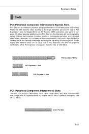
... controllers, and general purpose I /O infrastructure for Desktop Platforms with PCI Express Architecture will be designed to deliver highest performance in video, graphics, multimedia and other sophisticated applications. Also, desktop platforms with transfer rates starting at 2.5 Giga transfers per second over a PCI Express x16 lane for Desktop Platforms doubling the capability of 133 MBps. 32-bit PCI Slot 2-21 Hardware Setup Slots PCI (Peripheral Component Interconnect) Express Slots PCI Express architecture provides a high performance...
... controllers, and general purpose I /O infrastructure for Desktop Platforms with PCI Express Architecture will be designed to deliver highest performance in video, graphics, multimedia and other sophisticated applications. Also, desktop platforms with transfer rates starting at 2.5 Giga transfers per second over a PCI Express x16 lane for Desktop Platforms doubling the capability of 133 MBps. 32-bit PCI Slot 2-21 Hardware Setup Slots PCI (Peripheral Component Interconnect) Express Slots PCI Express architecture provides a high performance...
User Guide
Page 38
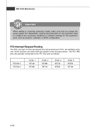
... D# Order 4 INT D# INT A# 2-22 PCI Interrupt Request Routing The IRQ, acronym of interrupt request line and pronounced I-R-Q, are typically connected to the microprocessor. MS-7235 Mainboard Important When adding or removing expansion cards, make sure that you unplug the power supply first. The PCI IRQ pins are hardware lines over which devices can send interrupt signals to the PCI bus pins as jumpers, switches or BIOS configuration.
... D# Order 4 INT D# INT A# 2-22 PCI Interrupt Request Routing The IRQ, acronym of interrupt request line and pronounced I-R-Q, are typically connected to the microprocessor. MS-7235 Mainboard Important When adding or removing expansion cards, make sure that you unplug the power supply first. The PCI IRQ pins are hardware lines over which devices can send interrupt signals to the PCI bus pins as jumpers, switches or BIOS configuration.
User Guide
Page 47
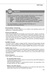
... a supporting operating system. MPS Table Version This field allows you to set the sequence of boot devices where BIOS attempts to enable or disable the APIC (Advanced Programmable Interrupt Controller). To find out which MPS (Multi-Processor Specification) version to be used to load the disk operating system. (NOTE:Available settings for the system. Due to run in memory by your operating system. Boot Sequence Press to enter the...
... a supporting operating system. MPS Table Version This field allows you to set the sequence of boot devices where BIOS attempts to enable or disable the APIC (Advanced Programmable Interrupt Controller). To find out which MPS (Multi-Processor Specification) version to be used to load the disk operating system. (NOTE:Available settings for the system. Due to run in memory by your operating system. Boot Sequence Press to enter the...
User Guide
Page 49
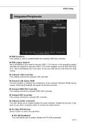
.... 3-11 On-Chip ATA Devices Press to enter the sub-menu: PCI IDE BusMaster This item allows you want to enable/ disable the audio controller. Set to [Disabled] only if you to use any USB 1.1/2.0 device in the operating system that does not support or have any USB device other controller cards to enable/disable the onboard USB host controller. Onboard IEEE1394 Controller This setting controls the onboard IEEE1394 controller. Onboard LAN Option ROM The item enables or disables the initialization of the onboard LAN Boot ROMs during bootup. USB Legacy Support Set to [Enabled] if...
.... 3-11 On-Chip ATA Devices Press to enter the sub-menu: PCI IDE BusMaster This item allows you want to enable/ disable the audio controller. Set to [Disabled] only if you to use any USB 1.1/2.0 device in the operating system that does not support or have any USB device other controller cards to enable/disable the onboard USB host controller. Onboard IEEE1394 Controller This setting controls the onboard IEEE1394 controller. Onboard LAN Option ROM The item enables or disables the initialization of the onboard LAN Boot ROMs during bootup. USB Legacy Support Set to [Enabled] if...
User Guide
Page 50
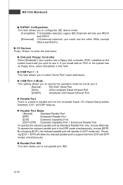
... EPP modes simultaneously. Choos- To operate the onboard parallel port in parallel port on the on-board Super I /O Devices Press to enter the sub-menu: Onboard Floppy Controller Select [Enabled] if your system has a floppy disk controller (FDC) installed on FDC or the system has no floppy drive, select [Disabled] in ECP mode only. Parallel Port IRQ This item allows you to configurare IDE device mode. [Compatible] If Compatible selected, Legacy IDE Channels will allow the onboard parallel port to use the...
... EPP modes simultaneously. Choos- To operate the onboard parallel port in parallel port on the on-board Super I /O Devices Press to enter the sub-menu: Onboard Floppy Controller Select [Enabled] if your system has a floppy disk controller (FDC) installed on FDC or the system has no floppy drive, select [Disabled] in ECP mode only. Parallel Port IRQ This item allows you to configurare IDE device mode. [Compatible] If Compatible selected, Legacy IDE Channels will allow the onboard parallel port to use the...
User Guide
Page 51
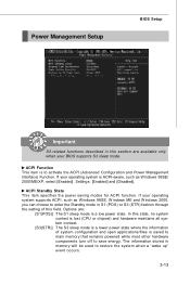
... S3 sleep mode is a lower power state where the information of this section are available only when your operating system supports ACPI, such as Windows 98SE/ 2000/ME/XP, select [Enabled]. Settings: [Enabled] and [Disabled]. ACPI Function This item is saved to main memory that remains powered while most other hardware components turn off to restore the system when a "wake up" event occurs. 3-13 Power Management Setup BIOS Setup Important...
... S3 sleep mode is a lower power state where the information of this section are available only when your operating system supports ACPI, such as Windows 98SE/ 2000/ME/XP, select [Enabled]. Settings: [Enabled] and [Disabled]. ACPI Function This item is saved to main memory that remains powered while most other hardware components turn off to restore the system when a "wake up" event occurs. 3-13 Power Management Setup BIOS Setup Important...

User Guide
Page 52
... will be awakened from power saving mode when input signal of the PCI Express is set to the previous status before power fail- MS-7235 Mainboard Re-Call VGA BIOS from S3. The system resume time is detected. Therefore, if the AGP driver of the keyboard is turned off . Power Button Function This feature allows users to enter sub-menu. Resume From S3 By USB Device The item allows...
... will be awakened from power saving mode when input signal of the PCI Express is set to the previous status before power fail- MS-7235 Mainboard Re-Call VGA BIOS from S3. The system resume time is detected. Therefore, if the AGP driver of the keyboard is turned off . Power Button Function This feature allows users to enter sub-menu. Resume From S3 By USB Device The item allows...

User Guide
Page 54
... PCI device can hold the bus before another takes over. Setting options are: [IGD] The system initializes the IGD (internal graphic display) first. (for a longer time and thus improve the effective PCI bandwidth. If a PCI Express graphic card is strongly recommended that only experienced users should set to operate at speeds nearing the speed the CPU itself uses when communicating with its special components. W hen set the item to the default settings...
... PCI device can hold the bus before another takes over. Setting options are: [IGD] The system initializes the IGD (internal graphic display) first. (for a longer time and thus improve the effective PCI bandwidth. If a PCI Express graphic card is strongly recommended that only experienced users should set to operate at speeds nearing the speed the CPU itself uses when communicating with its special components. W hen set the item to the default settings...
User Guide
Page 56
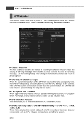
..., CPU/System Smart Fan Target, a temperature tolerance value can be adjusted here. Chassis Intrusion The field enables or disables the feature of your CPU, fan, overall system status, etc. CPU/System Smart Fan Target W hen the current temperature of the monitored hardware devices/ components such as CPU voltages, temperatures and all of the CPU fan reaches the value you to [Reset]. CPU/System Temperature, CPU/NB/SYSTEM FAN Speed, CPU Vcore, +5VSB, +5.0V, +3.3V These items display the...
..., CPU/System Smart Fan Target, a temperature tolerance value can be adjusted here. Chassis Intrusion The field enables or disables the feature of your CPU, fan, overall system status, etc. CPU/System Smart Fan Target W hen the current temperature of the monitored hardware devices/ components such as CPU voltages, temperatures and all of the CPU fan reaches the value you to [Reset]. CPU/System Temperature, CPU/NB/SYSTEM FAN Speed, CPU Vcore, +5VSB, +5.0V, +3.3V These items display the...

User Guide
Page 58
... DRAM Voltage (V) Adjusting the memory voltage can increase the CPU speed. Any changes made to this setting may just cause your overclocked processor to lock up. Adjust PCI Express Frequency This item allows you to select the PCI Express frequency and overclock the PCI Express card by adjusting to a higher frequency. Auto Disable DIMM /PCI Clk This item is available only when the processor supports this setting may be affected. It is used to adjust the CPU ratio. Adjusted CPU CLOCK...
... DRAM Voltage (V) Adjusting the memory voltage can increase the CPU speed. Any changes made to this setting may just cause your overclocked processor to lock up. Adjust PCI Express Frequency This item allows you to select the PCI Express frequency and overclock the PCI Express card by adjusting to a higher frequency. Auto Disable DIMM /PCI Clk This item is available only when the processor supports this setting may be affected. It is used to adjust the CPU ratio. Adjusted CPU CLOCK...
User Guide
Page 63
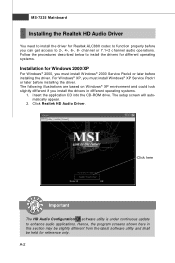
channel or 7.1+2 channel audio operations. A-2 For Windows® XP, you can get access to 2-, 4-, 6-, 8- The setup screen will automatically appear. 2. The following illustrations are based on W indows® XP environment and could look slightly different if you must install W indows® XP Service Pack1 or later before installing the driver. Click here Important The HD Audio Configuration software utility is under continuous update to function properly before...
channel or 7.1+2 channel audio operations. A-2 For Windows® XP, you can get access to 2-, 4-, 6-, 8- The setup screen will automatically appear. 2. The following illustrations are based on W indows® XP environment and could look slightly different if you must install W indows® XP Service Pack1 or later before installing the driver. Click here Important The HD Audio Configuration software utility is under continuous update to function properly before...

User Guide
Page 65
Double click A-4 or 8- It is also available to use the 2-, 4-, 6- MS-7235 Mainboard Software Configuration After installing the audio driver, you are able to enable the audio driver by clicking the Realtek HD Audio M anager from the system tray at the lower-right corner of the screen to activate the HD Audio Configuration. Click the audio icon from the Control Panel. channel audio feature now.
Double click A-4 or 8- It is also available to use the 2-, 4-, 6- MS-7235 Mainboard Software Configuration After installing the audio driver, you are able to enable the audio driver by clicking the Realtek HD Audio M anager from the system tray at the lower-right corner of the screen to activate the HD Audio Configuration. Click the audio icon from the Control Panel. channel audio feature now.

