
User Guide
Page 8
...AM2 2-4 Installing AMD Socket AM2 CPU Cooler Set 2-5 Memory ...2-6 Memory Module Population Rules 2-6 Installing DDRII Modules 2-7 Power Supply ...2-8 ATX 24-Pin Power Connector: ATX1 2-8 ATX 12V Power Connector: JPW 1 2-8 Back Panel ...2-9 Connectors ...2-11 Floppy Disk Drive Connector: FDD1 2-11 ATA133 Hard Disk Connectors: IDE1... 2-16 IEEE 1394 Connectors: J1394_1 2-17 SPDIF-Out / SPDIF-In Connector: SPDOUT1 / SPDIN1 (Optional 2-18 viii Getting Started 1-1 Mainboard Specifications 1-2 Mainboard Layout 1-4 Packing Checklist 1-4 Setup audio output to HDMI port 1-6 Chapter 2.
...AM2 2-4 Installing AMD Socket AM2 CPU Cooler Set 2-5 Memory ...2-6 Memory Module Population Rules 2-6 Installing DDRII Modules 2-7 Power Supply ...2-8 ATX 24-Pin Power Connector: ATX1 2-8 ATX 12V Power Connector: JPW 1 2-8 Back Panel ...2-9 Connectors ...2-11 Floppy Disk Drive Connector: FDD1 2-11 ATA133 Hard Disk Connectors: IDE1... 2-16 IEEE 1394 Connectors: J1394_1 2-17 SPDIF-Out / SPDIF-In Connector: SPDOUT1 / SPDIN1 (Optional 2-18 viii Getting Started 1-1 Mainboard Specifications 1-2 Mainboard Layout 1-4 Packing Checklist 1-4 Setup audio output to HDMI port 1-6 Chapter 2.
User Guide
Page 10
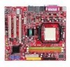
The K9AGM2 Series mainboards are based on AMD® 690G/690V & SB600 chipsets for choosing the K9AGM2 Series (MS-7327 v1.X) Micro-AT X mainboard. Designed to fit the advanced AM D® Athlon 64 X2/ Athlon 64 processor, the K9AGM2 Series deliver a high performance and professional desktop platform solution. 1-1 Getting Started Chapter 1 Getting Started Thank you for optimal system efficiency.
The K9AGM2 Series mainboards are based on AMD® 690G/690V & SB600 chipsets for choosing the K9AGM2 Series (MS-7327 v1.X) Micro-AT X mainboard. Designed to fit the advanced AM D® Athlon 64 X2/ Athlon 64 processor, the K9AGM2 Series deliver a high performance and professional desktop platform solution. 1-1 Getting Started Chapter 1 Getting Started Thank you for optimal system efficiency.
User Guide
Page 11
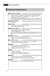
...1.8V) (For m ore information on compatible components, please visit http:/ /www.msi.com.tw/program/products/mainboard/mbd/pro_mbd_trp_list. Supports 2 IEEE1394 ports, transfer rate is up to 300MB/s RAID - MS-7327 Mainboard Mainboard Specifications Processor Support - North Bridge: AMD® 690G/ 690V chipset - AMD&#..., Bus Master operation mode SATA - Supports 4 pin CPU Fan Pin-Header with Fan Speed Control - com.tw/program/products/mainboard/mbd/pro_mbd_cpu_support.php) Supported FSB - 1000 MHz Chipset - Supports 10/100/1000 Fast Ethernet by VIA VT6308 (optional) Audio ...
...1.8V) (For m ore information on compatible components, please visit http:/ /www.msi.com.tw/program/products/mainboard/mbd/pro_mbd_trp_list. Supports 2 IEEE1394 ports, transfer rate is up to 300MB/s RAID - MS-7327 Mainboard Mainboard Specifications Processor Support - North Bridge: AMD® 690G/ 690V chipset - AMD&#..., Bus Master operation mode SATA - Supports 4 pin CPU Fan Pin-Header with Fan Speed Control - com.tw/program/products/mainboard/mbd/pro_mbd_cpu_support.php) Supported FSB - 1000 MHz Chipset - Supports 10/100/1000 Fast Ethernet by VIA VT6308 (optional) Audio ...
User Guide
Page 13
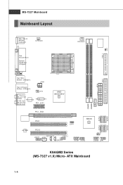
FDD 1 JCI1 MS-7327 Mainboard Mainboard Layout Top : mouse Bottom: ke ybo ar d SYSFAN1 CP U FA N 1 Top : Parallel Port B ot to m : HDMI port VGA port AT X 1 IDE 1 To p: 1 39 4 Bottom: USB ports JPW1 Top: LAN Jack Bottom: USB ports JTV1 T: L in e- ATX Mainboard SATA 1 S ATA3 1-4 O u t M:CS-Out B:SS-O ut RTM 870T- 691 PCI _EX1 AMD 6 9 0 G/ 6 90 V DIMM1 DIMM2 BAT T + PCI _EX2 PCI1 ALC888 PCI 2 SPDOUT1 JAU D1 JC D1 JSPI1 SB600 S ATA4 JUSB1 JUSB2 J B AT 1 JUSB3 JFP1 SATA 2 K9AGM2 Series (MS-7327 v1.X) Micro- I n M:Line-Out B:Mic RT L8111 B T: R S -
FDD 1 JCI1 MS-7327 Mainboard Mainboard Layout Top : mouse Bottom: ke ybo ar d SYSFAN1 CP U FA N 1 Top : Parallel Port B ot to m : HDMI port VGA port AT X 1 IDE 1 To p: 1 39 4 Bottom: USB ports JPW1 Top: LAN Jack Bottom: USB ports JTV1 T: L in e- ATX Mainboard SATA 1 S ATA3 1-4 O u t M:CS-Out B:SS-O ut RTM 870T- 691 PCI _EX1 AMD 6 9 0 G/ 6 90 V DIMM1 DIMM2 BAT T + PCI _EX2 PCI1 ALC888 PCI 2 SPDOUT1 JAU D1 JC D1 JSPI1 SB600 S ATA4 JUSB1 JUSB2 J B AT 1 JUSB3 JFP1 SATA 2 K9AGM2 Series (MS-7327 v1.X) Micro- I n M:Line-Out B:Mic RT L8111 B T: R S -
User Guide
Page 15
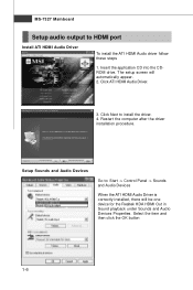
... Panel -> Sounds and Audio Devices W hen the ATI HDMI Audio Driver is correctly installed, there will automatically appear. 2. Click ATI HDMI Audio Driver. 3. MS-7327 Mainboard Setup audio output to install the driver. 4.
... Panel -> Sounds and Audio Devices W hen the ATI HDMI Audio Driver is correctly installed, there will automatically appear. 2. Click ATI HDMI Audio Driver. 3. MS-7327 Mainboard Setup audio output to install the driver. 4.
User Guide
Page 18
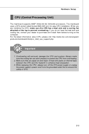
...) between the CPU and the heatsink to enhance heat dissipation. 3. For the latest information about CPU, please visit http://www.msi.com.tw/program/ products/mainboard/mbd/pro_mbd_cpu_support.php Important 1. Overheating will seriously damage the CPU and system. W hen you do not have the heat sink ...the ATX power supply or unplug the power supply's power cord from overheating. 2. Always make sure the CPU has a heat sink and a cooling fan attached on the top to purchase and install them before turning on the computer. Hardware Setup CPU (Central Processing Unit) The mainboard supports...
...) between the CPU and the heatsink to enhance heat dissipation. 3. For the latest information about CPU, please visit http://www.msi.com.tw/program/ products/mainboard/mbd/pro_mbd_cpu_support.php Important 1. Overheating will seriously damage the CPU and system. W hen you do not have the heat sink ...the ATX power supply or unplug the power supply's power cord from overheating. 2. Always make sure the CPU has a heat sink and a cooling fan attached on the top to purchase and install them before turning on the computer. Hardware Setup CPU (Central Processing Unit) The mainboard supports...
User Guide
Page 19
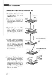
... note that any violation of the CPU. If the CPU is properly and completely embedded into the socket and close the lever with your mainboard. MS-7327 Mainboard CPU Installation Procedures for the gold arrow of the correct installation procedures may cause permanent damages to your fingers pressing tightly on top of...
... note that any violation of the CPU. If the CPU is properly and completely embedded into the socket and close the lever with your mainboard. MS-7327 Mainboard CPU Installation Procedures for the gold arrow of the correct installation procedures may cause permanent damages to your fingers pressing tightly on top of...
User Guide
Page 20
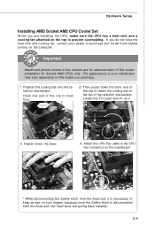
... the CPU Fan cable to keep an eye on the computer. If you do not have the heat sink and cooling fan, contact your mainboard may vary depending on the model you are for demonstration of the clip to purchase and install them before turning on your fingers, because once... the Safety Hook is necessary to the CPU fan connector on the mainboard. * While disconnecting the Safety Hook from the fixed bolt, the fixed lever will spring back instantly. 2-5 The appearance of the clip to prevent overheating...
... the CPU Fan cable to keep an eye on the computer. If you do not have the heat sink and cooling fan, contact your mainboard may vary depending on the model you are for demonstration of the clip to purchase and install them before turning on your fingers, because once... the Safety Hook is necessary to the CPU fan connector on the mainboard. * While disconnecting the Safety Hook from the fixed bolt, the fixed lever will spring back instantly. 2-5 The appearance of the clip to prevent overheating...
User Guide
Page 21
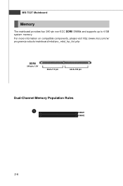
MS-7327 Mainboard Memory The mainboard provides four 240-pin non-ECC DDRII DIMMs and supports up to 4 GB system memory. For more information on compatible components, please visit http://www.msi.com.tw/ p ro gr a m/ pr o du c t s /m ain bo ar d /m bd / pr o_ m bd _t r p_ lis t. ph p DDRII 240-pin, 1.8V 56x2=112 pin 64x2=128 pin Dual-Channel Memory Population Rules 1 DIMM1 DIMM2 2-6
MS-7327 Mainboard Memory The mainboard provides four 240-pin non-ECC DDRII DIMMs and supports up to 4 GB system memory. For more information on compatible components, please visit http://www.msi.com.tw/ p ro gr a m/ pr o du c t s /m ain bo ar d /m bd / pr o_ m bd _t r p_ lis t. ph p DDRII 240-pin, 1.8V 56x2=112 pin 64x2=128 pin Dual-Channel Memory Population Rules 1 DIMM1 DIMM2 2-6

User Guide
Page 23
...-pin power supply. To connect the ATX 24-pin power supply, make sure the plug of 350 watts (and above) is used to provide power to ensure stable operation of the mainboard. 2. If you like to the image at the right hand). JPW1 4 2 3 1 JPW1 Pin Definition PIN SIGNAL 1 GND 2... GND 3 12V 4 12V Important 1. Then push down the power supply firmly into the connector. You may use the 20-pin ATX power supply, please plug...
...-pin power supply. To connect the ATX 24-pin power supply, make sure the plug of 350 watts (and above) is used to provide power to ensure stable operation of the mainboard. 2. If you like to the image at the right hand). JPW1 4 2 3 1 JPW1 Pin Definition PIN SIGNAL 1 GND 2... GND 3 12V 4 12V Important 1. Then push down the power supply firmly into the connector. You may use the 20-pin ATX power supply, please plug...
User Guide
Page 25
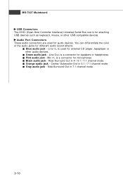
... mode. 2-10 Audio Port Connectors These audio connectors are used for external CD player, tapeplayer or other USB-compatible devices. Pink audio jack - MS-7327 Mainboard USB Connectors The OHCI (Open Host Controller Interface) Universal Serial Bus root is for attaching USB devices such as keyboard, mouse, or other audio devices...
... mode. 2-10 Audio Port Connectors These audio connectors are used for external CD player, tapeplayer or other USB-compatible devices. Pink audio jack - MS-7327 Mainboard USB Connectors The OHCI (Open Host Controller Interface) Universal Serial Bus root is for attaching USB devices such as keyboard, mouse, or other audio devices...
User Guide
Page 26
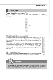
... than earlier record-breaking Ultra ATA/ 100 technology and is backwards compatible with the existing Ultra ATA interface. FDD1 ATA133 Hard Disk Connectors: IDE1 The mainboard has a 32-bit Enhanced PCI IDE and Ultra DMA 66/100/133 controller that provides PIO mode 0~4, Bus Master, and Ultra DMA 66/ 100/133...
... than earlier record-breaking Ultra ATA/ 100 technology and is backwards compatible with the existing Ultra ATA interface. FDD1 ATA133 Hard Disk Connectors: IDE1 The mainboard has a 32-bit Enhanced PCI IDE and Ultra DMA 66/100/133 controller that provides PIO mode 0~4, Bus Master, and Ultra DMA 66/ 100/133...

User Guide
Page 27
.... Each supports data rates of 300 MB/s and is fully compliant with Serial ATA specifications. Otherwise, data loss may occur during transmission. 2-12 MS-7327 Mainboard Serial ATA II Connectors: SATA1~SATA4 SATA1~SATA4 are high-speed SATAII interface ports.
.... Each supports data rates of 300 MB/s and is fully compliant with Serial ATA specifications. Otherwise, data loss may occur during transmission. 2-12 MS-7327 Mainboard Serial ATA II Connectors: SATA1~SATA4 SATA1~SATA4 are high-speed SATAII interface ports.
User Guide
Page 28
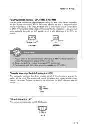
... to the connectors, always take advantage of the CPU fan c on -board, you must use a specially designed fan with speed sensor to GND. If the mainboard has a System Hardware Monitor chipset on tr ol .
... to the connectors, always take advantage of the CPU fan c on -board, you must use a specially designed fan with speed sensor to GND. If the mainboard has a System Hardware Monitor chipset on tr ol .
User Guide
Page 29
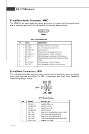
... front panel 10 AUD_RET_L Left channel audio signal return from front panel Front Panel Connectors: JFP1 The mainboard provides two front panel connectors for electrical connection to the front panel switches and LEDs. MS-7327 Mainboard Front Panel Audio Connector: JAUD1 The JAUD1 front panel audio connector allows you to connect the...
... front panel 10 AUD_RET_L Left channel audio signal return from front panel Front Panel Connectors: JFP1 The mainboard provides two front panel connectors for electrical connection to the front panel switches and LEDs. MS-7327 Mainboard Front Panel Audio Connector: JAUD1 The JAUD1 front panel audio connector allows you to connect the...
User Guide
Page 30
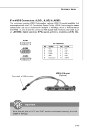
Hardware Setup Front USB Connectors: JUSB1, JUSB2 & JUSB3 The mainboard provides USB 2.0 pinheaders (optional USB 2.0 bracket available) that the pins of 480Mbps, which is 40 times faster than USB 1.1, and is ideal for connecting high-...
Hardware Setup Front USB Connectors: JUSB1, JUSB2 & JUSB3 The mainboard provides USB 2.0 pinheaders (optional USB 2.0 bracket available) that the pins of 480Mbps, which is 40 times faster than USB 1.1, and is ideal for connecting high-...
User Guide
Page 31
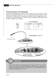
... choose either the RCA Composite or the S-Video to the malfunction of TV-Out connectors: S-Video and RCA Composite connectors. MS-7327 Mainboard TV-Out Connector: JTV1 (Optional) The mainboard optionally provides a TV-Out connector for you to attach a TV-Out bracket that the TV-Out bracket can connect to one to...
... choose either the RCA Composite or the S-Video to the malfunction of TV-Out connectors: S-Video and RCA Composite connectors. MS-7327 Mainboard TV-Out Connector: JTV1 (Optional) The mainboard optionally provides a TV-Out connector for you to attach a TV-Out bracket that the TV-Out bracket can connect to one to...
User Guide
Page 32
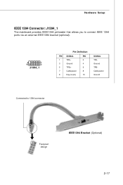
Hardware Setup IEEE 1394 Connector: J1394_1 The mainboard provides IEEE1394 pinheader that allows you to connect IEEE 1394 ports via an external IEEE1394 bracket (optional). 9 1 10 2 J1394_1 Pin Definition PIN SIGNAL PIN 1 TPA+ 2 3 Ground 4 5 TPB+ 6 7 Cable power 8 9 Key (no pin) 10 SIGNAL TPAGround TPBCable power Ground Connected to 1394 connector Foolproof design IEEE1394 Bracket (Optional) 2-17
Hardware Setup IEEE 1394 Connector: J1394_1 The mainboard provides IEEE1394 pinheader that allows you to connect IEEE 1394 ports via an external IEEE1394 bracket (optional). 9 1 10 2 J1394_1 Pin Definition PIN SIGNAL PIN 1 TPA+ 2 3 Ground 4 5 TPB+ 6 7 Cable power 8 9 Key (no pin) 10 SIGNAL TPAGround TPBCable power Ground Connected to 1394 connector Foolproof design IEEE1394 Bracket (Optional) 2-17
User Guide
Page 33
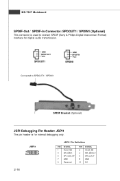
JSPI1 9 1 10 2 JSPI1 Pin Definition PIN SIGNAL 1 VCC3_SB 3 SPI_MISO 5 SPI_CSO_F# 7 GND 9 Reserved PIN SIGNAL 2 VCC3_SB 4 SPI_MOSI_F 6 SPI_CLK_F 8 GND 10 NC 2-18 GND SPDIF OUT VCC SPDOUT1 GND SPDIF IN VCC SPDIN1 Connected to connect SPDIF (Sony & Philips Digital Interconnect Format) interface for internal debugging only. MS-7327 Mainboard SPDIF-Out / SPDIF-In Connector: SPDOUT1 / SPDIN1 (Optional) This connector is used to SPDOUT1 / SPDIN1 SPDIF Bracket (Optional) JSPI Debugging Pin Header: JSPI1 The pin header is for digital audio transmission.
JSPI1 9 1 10 2 JSPI1 Pin Definition PIN SIGNAL 1 VCC3_SB 3 SPI_MISO 5 SPI_CSO_F# 7 GND 9 Reserved PIN SIGNAL 2 VCC3_SB 4 SPI_MOSI_F 6 SPI_CLK_F 8 GND 10 NC 2-18 GND SPDIF OUT VCC SPDOUT1 GND SPDIF IN VCC SPDIN1 Connected to connect SPDIF (Sony & Philips Digital Interconnect Format) interface for internal debugging only. MS-7327 Mainboard SPDIF-Out / SPDIF-In Connector: SPDOUT1 / SPDIN1 (Optional) This connector is used to SPDOUT1 / SPDIN1 SPDIF Bracket (Optional) JSPI Debugging Pin Header: JSPI1 The pin header is for digital audio transmission.
User Guide
Page 34
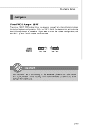
... a power supply from external battery to 1-2 pin position. JBAT1 1 1 3 Keep Data 1 3 Clear Data Important You can automatically boot OS every time it will damage the mainboard. 2-19 If you want to clear the system configuration, set the JBAT1 (Clear CMOS Jumper ) to clear data. it is turned on ;
... a power supply from external battery to 1-2 pin position. JBAT1 1 1 3 Keep Data 1 3 Clear Data Important You can automatically boot OS every time it will damage the mainboard. 2-19 If you want to clear the system configuration, set the JBAT1 (Clear CMOS Jumper ) to clear data. it is turned on ;


