
User Guide
Page 8
... Components Guide 2-2 CPU (Central Processing Unit 2-2 CPU Installation Procedures for Socket AM2 2-4 Installing AMD Socket AM2 CPU Cooler Set 2-5 Memory ...2-6 Memory Module Population Rules 2-6 Installing DDRII Modules 2-7 Power Supply ...2-8 ATX 24-Pin Power Connector: ATX1 2-8 ATX 12V Power Connector: JPW 1 2-8 Back Panel ...2-9 Connectors ...2-11 Floppy Disk Drive Connector: FDD1 2-11 ATA133 Hard Disk Connectors...
... Components Guide 2-2 CPU (Central Processing Unit 2-2 CPU Installation Procedures for Socket AM2 2-4 Installing AMD Socket AM2 CPU Cooler Set 2-5 Memory ...2-6 Memory Module Population Rules 2-6 Installing DDRII Modules 2-7 Power Supply ...2-8 ATX 24-Pin Power Connector: ATX1 2-8 ATX 12V Power Connector: JPW 1 2-8 Back Panel ...2-9 Connectors ...2-11 Floppy Disk Drive Connector: FDD1 2-11 ATA133 Hard Disk Connectors...
User Guide
Page 11
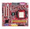
... Supports 2 IEEE1394 ports, transfer rate is up to 5000+ and higter CPU (For the latest inform ation about CPU, please visit http://www.msi. Flexible 8-channel audio with Fan Speed Control - Compliant with Azalia 1.0 spec IDE - 1 IDE port by 8101E - Supports 10/100 Fast Ethernet... by SB600 - Supports RAID 0, 1 and 0+1 mode by Realtek® ALC888 - South Bridge: SB600 chipset Memory Support - DDRII 800/667/533/400 DRAM (4GB Max) - 2 DDRII DIMMs (240pin / 1.8V) (For m ore information on compatible components, please visit http...
... Supports 2 IEEE1394 ports, transfer rate is up to 5000+ and higter CPU (For the latest inform ation about CPU, please visit http://www.msi. Flexible 8-channel audio with Fan Speed Control - Compliant with Azalia 1.0 spec IDE - 1 IDE port by 8101E - Supports 10/100 Fast Ethernet... by SB600 - Supports RAID 0, 1 and 0+1 mode by Realtek® ALC888 - South Bridge: SB600 chipset Memory Support - DDRII 800/667/533/400 DRAM (4GB Max) - 2 DDRII DIMMs (240pin / 1.8V) (For m ore information on compatible components, please visit http...
User Guide
Page 21
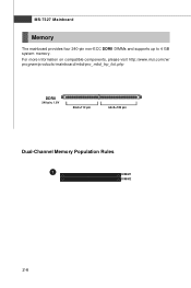
MS-7327 Mainboard Memory The mainboard provides four 240-pin non-ECC DDRII DIMMs and supports up to 4 GB system memory. ph p DDRII 240-pin, 1.8V 56x2=112 pin 64x2=128 pin Dual-Channel Memory Population Rules 1 DIMM1 DIMM2 2-6 For more information on compatible components, please visit http://www.msi.com.tw/ p ro gr a m/ pr o du c t s /m ain bo ar d /m bd / pr o_ m bd _t r p_ lis t.
MS-7327 Mainboard Memory The mainboard provides four 240-pin non-ECC DDRII DIMMs and supports up to 4 GB system memory. ph p DDRII 240-pin, 1.8V 56x2=112 pin 64x2=128 pin Dual-Channel Memory Population Rules 1 DIMM1 DIMM2 2-6 For more information on compatible components, please visit http://www.msi.com.tw/ p ro gr a m/ pr o du c t s /m ain bo ar d /m bd / pr o_ m bd _t r p_ lis t.
User Guide
Page 22
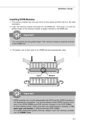
.... Then push it in until the golden finger on the center and will automatically close. You should always install DDRII memory modules in the DDRII DIMMs and DDR memory modules in the right orientation. 2. DDRII modules are not interchangeable with DDR and the DDRII standard is deeply inserted in... the DIMM slot. To enable successful system boot-up, always insert the memory modules into the DIMM slot. Hardware Setup Installing DDRII Modules 1. The plastic clip at each side of the same type and density in ...
.... Then push it in until the golden finger on the center and will automatically close. You should always install DDRII memory modules in the DDRII DIMMs and DDR memory modules in the right orientation. 2. DDRII modules are not interchangeable with DDR and the DDRII standard is deeply inserted in... the DIMM slot. To enable successful system boot-up, always insert the memory modules into the DIMM slot. Hardware Setup Installing DDRII Modules 1. The plastic clip at each side of the same type and density in ...
User Guide
Page 38
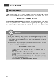
... below appears on the computer and the system will start POST (Power On Self Test) process. Upon boot-up, the 1st line appearing after the memory count is usually in this BIOS was released. 3-2 V1.0 refers to the BIOS version. 050506 refers to enter Setup. Important 1. It is the BIOS version...
... below appears on the computer and the system will start POST (Power On Self Test) process. Upon boot-up, the 1st line appearing after the memory count is usually in this BIOS was released. 3-2 V1.0 refers to the BIOS version. 050506 refers to enter Setup. Important 1. It is the BIOS version...
User Guide
Page 44
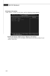
MS-7327 Mainboard System Information Press to enter the sub-menu, and the following screen appears. CPU Infromation/ BIOS Version/ M emory Information These items show the CPU information, BIOS version and memory status of your system (read only). 3-8
MS-7327 Mainboard System Information Press to enter the sub-menu, and the following screen appears. CPU Infromation/ BIOS Version/ M emory Information These items show the CPU information, BIOS version and memory status of your system (read only). 3-8
User Guide
Page 47
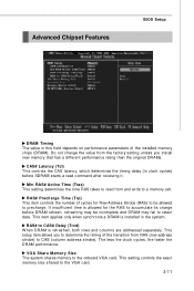
This setup item allows you install new memory that has a different performance rating than the original DRAMs. CAS# Latency (Tcl) This controls the CAS latency, which determines the timing delay (in RAS# Active ... the DRAM performance. RAS# Precharge Time (Trp) This item controls the number of the installed memory chips (DRAM). This setting controls the exact memory size shared to the onboard VGA card. VGA Share Memory Size The system shares memory to the VGA card. 3-11 This item applies only when synchronous DRAM is installed in...
This setup item allows you install new memory that has a different performance rating than the original DRAMs. CAS# Latency (Tcl) This controls the CAS latency, which determines the timing delay (in RAS# Active ... the DRAM performance. RAS# Precharge Time (Trp) This item controls the number of the installed memory chips (DRAM). This setting controls the exact memory size shared to the onboard VGA card. VGA Share Memory Size The system shares memory to the VGA card. 3-11 This item applies only when synchronous DRAM is installed in...
User Guide
Page 51
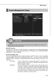
... the in S1(POS) or S3(STR) fashion through the setting of system configuration and open applications/files is saved to main memory that remains powered while most other hardware components turn off to save energy. If your operating system supports ACPI, such as Windows ...XP, select [Enabled]. tem when a "wake up" event occurs. 3-15 Power Management Setup BIOS Setup Important S3-related functions described in memory will be used to restore the sys- ACPI Standby State This item specifies the power saving modes for ACPI function. The information stored in this...
... the in S1(POS) or S3(STR) fashion through the setting of system configuration and open applications/files is saved to main memory that remains powered while most other hardware components turn off to save energy. If your operating system supports ACPI, such as Windows ...XP, select [Enabled]. tem when a "wake up" event occurs. 3-15 Power Management Setup BIOS Setup Important S3-related functions described in memory will be used to restore the sys- ACPI Standby State This item specifies the power saving modes for ACPI function. The information stored in this...
User Guide
Page 58
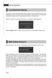
...: Type the password, up to confirm the password. W hen a password has been set password from changing any password. This prevents an unauthorized person from CMOS memory. W hen you will replace any previously set , you select Load Optimized Defaults, a message as below appears: Selecting [OK] loads the default factory settings for optimal...
...: Type the password, up to confirm the password. W hen a password has been set password from changing any password. This prevents an unauthorized person from CMOS memory. W hen you will replace any previously set , you select Load Optimized Defaults, a message as below appears: Selecting [OK] loads the default factory settings for optimal...


