
User Guide
Page 8
... 1-4 Packing Checklist 1-4 Setup audio output to HDMI port 1-6 Chapter 2. Hardware Setup 2-1 Quick Components Guide 2-2 CPU (Central Processing Unit 2-2 CPU Installation Procedures for Socket AM2 2-4 Installing AMD Socket AM2 CPU Cooler Set 2-5 Memory ...2-6 Memory Module Population Rules 2-6 Installing DDRII Modules 2-7 Power Supply ...2-8 ATX 24-Pin Power Connector: ATX1 2-8 ATX 12V Power Connector: JPW 1 2-8 Back...
... 1-4 Packing Checklist 1-4 Setup audio output to HDMI port 1-6 Chapter 2. Hardware Setup 2-1 Quick Components Guide 2-2 CPU (Central Processing Unit 2-2 CPU Installation Procedures for Socket AM2 2-4 Installing AMD Socket AM2 CPU Cooler Set 2-5 Memory ...2-6 Memory Module Population Rules 2-6 Installing DDRII Modules 2-7 Power Supply ...2-8 ATX 24-Pin Power Connector: ATX1 2-8 ATX 12V Power Connector: JPW 1 2-8 Back...
User Guide
Page 12
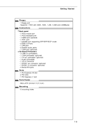
Micro-ATX (24.4cm X 21.5 cm) Mounting - 6 mounting holes 1-3 Getting Started Floppy - 1 floppy port - Supports 1 FDD with 360K, 720K, 1.2M, 1.44M and 2.88Mbytes Connectors Back panel - 1 PS/2 mouse port - 1 PS/2 keyboard port - 1 HDMI port (optional) - 1 VGA port - 1 parallel port supporting SPP/EPP/ECP mode - 4 USB 2.0 Ports - 1 LAN jack - 6 flexible audio jacks - 1 1394 port (optional...
Micro-ATX (24.4cm X 21.5 cm) Mounting - 6 mounting holes 1-3 Getting Started Floppy - 1 floppy port - Supports 1 FDD with 360K, 720K, 1.2M, 1.44M and 2.88Mbytes Connectors Back panel - 1 PS/2 mouse port - 1 PS/2 keyboard port - 1 HDMI port (optional) - 1 VGA port - 1 parallel port supporting SPP/EPP/ECP mode - 4 USB 2.0 Ports - 1 LAN jack - 6 flexible audio jacks - 1 1394 port (optional...
User Guide
Page 13
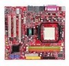
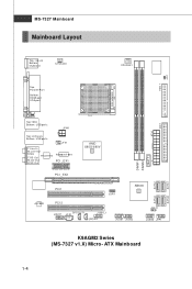
O u t M:CS-Out B:SS-O ut RTM 870T- 691 PCI _EX1 AMD 6 9 0 G/ 6 90 V DIMM1 DIMM2 BAT T + PCI _EX2 PCI1 ALC888 PCI 2 SPDOUT1 JAU D1 JC D1 JSPI1 SB600 S ATA4 JUSB1 JUSB2 J B AT 1 JUSB3 JFP1 SATA 2 K9AGM2 Series (MS-7327 v1.X) Micro- ATX Mainboard SATA 1 S ATA3 1-4 FDD 1 JCI1 MS-7327 Mainboard Mainboard Layout Top : mouse Bottom: ke ybo ar d SYSFAN1 CP U FA N 1 Top : Parallel Port B ot to m : HDMI port VGA port AT X 1 IDE 1 To p: 1 39 4 Bottom: USB ports JPW1 Top: LAN Jack Bottom: USB ports JTV1 T: L in e- I n M:Line-Out B:Mic RT L8111 B T: R S -
O u t M:CS-Out B:SS-O ut RTM 870T- 691 PCI _EX1 AMD 6 9 0 G/ 6 90 V DIMM1 DIMM2 BAT T + PCI _EX2 PCI1 ALC888 PCI 2 SPDOUT1 JAU D1 JC D1 JSPI1 SB600 S ATA4 JUSB1 JUSB2 J B AT 1 JUSB3 JFP1 SATA 2 K9AGM2 Series (MS-7327 v1.X) Micro- ATX Mainboard SATA 1 S ATA3 1-4 FDD 1 JCI1 MS-7327 Mainboard Mainboard Layout Top : mouse Bottom: ke ybo ar d SYSFAN1 CP U FA N 1 Top : Parallel Port B ot to m : HDMI port VGA port AT X 1 IDE 1 To p: 1 39 4 Bottom: USB ports JPW1 Top: LAN Jack Bottom: USB ports JTV1 T: L in e- I n M:Line-Out B:Mic RT L8111 B T: R S -
User Guide
Page 15
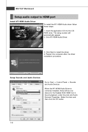
... Driver is correctly installed, there will automatically appear. 2. Restart the computer after the driver installation procedure. Click ATI HDMI Audio Driver. 3. Select the item and then click the OK button 1-6 Insert the application CD into the CDROM drive. Setup Sounds and Audio ...Devices Go to install the driver. 4. MS-7327 Mainboard Setup audio output to HDMI port Install ATI HDMI Audio Driver To install the ATI HDMI Audio driver follow these steps 1. The setup screen will be one device for the Realtek HDA...
... Driver is correctly installed, there will automatically appear. 2. Restart the computer after the driver installation procedure. Click ATI HDMI Audio Driver. 3. Select the item and then click the OK button 1-6 Insert the application CD into the CDROM drive. Setup Sounds and Audio ...Devices Go to install the driver. 4. MS-7327 Mainboard Setup audio output to HDMI port Install ATI HDMI Audio Driver To install the ATI HDMI Audio driver follow these steps 1. The setup screen will be one device for the Realtek HDA...
User Guide
Page 24
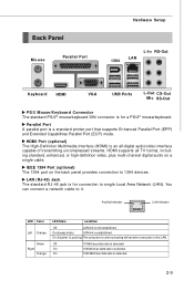
...channel digital audio on a single cable. IEEE 1394 Port (optional) The 1394 port on the LAN. HDM I Port (optional) The High-Definition Multimedia Interface (HDMI) is selected. On (brighter & pulsing) The computer is for a PS/2® mouse/keyboard. LAN (RJ-45) Jack The standard RJ-45 jack is ...On (steady state) LAN link is for connection to it. Back Panel Mouse Parallel Port Hardware Setup 1394 LAN L-In RS-Out Keyboard HDMI VG A USB Ports L-Out CS-Out Mic SS-Out PS/2 Mouse/Keyboard Connector The standard PS/2® mouse/keyboard DIN connector is established.
...channel digital audio on a single cable. IEEE 1394 Port (optional) The 1394 port on the LAN. HDM I Port (optional) The High-Definition Multimedia Interface (HDMI) is selected. On (brighter & pulsing) The computer is for a PS/2® mouse/keyboard. LAN (RJ-45) Jack The standard RJ-45 jack is ...On (steady state) LAN link is for connection to it. Back Panel Mouse Parallel Port Hardware Setup 1394 LAN L-In RS-Out Keyboard HDMI VG A USB Ports L-Out CS-Out Mic SS-Out PS/2 Mouse/Keyboard Connector The standard PS/2® mouse/keyboard DIN connector is established.

