
User Guide
Page 8
Hardware Setup 2-1 Quick Components Guide 2-2 CPU (Central Processing Unit 2-2 CPU Installation Procedures for Socket AM2 2-4 Installing AMD Socket AM2 CPU Cooler Set 2-5 Memory ...2-6 Memory Module Population Rules 2-6 Installing DDRII Modules 2-7 Power Supply ...2-8 ATX 24-Pin Power Connector: ATX1 2-8 ATX 12V Power Connector: JPW 1 2-8 Back Panel ...2-9 Connectors ...2-11 Floppy Disk Drive Connector: FDD1 2-11 ATA133 Hard Disk...
Hardware Setup 2-1 Quick Components Guide 2-2 CPU (Central Processing Unit 2-2 CPU Installation Procedures for Socket AM2 2-4 Installing AMD Socket AM2 CPU Cooler Set 2-5 Memory ...2-6 Memory Module Population Rules 2-6 Installing DDRII Modules 2-7 Power Supply ...2-8 ATX 24-Pin Power Connector: ATX1 2-8 ATX 12V Power Connector: JPW 1 2-8 Back Panel ...2-9 Connectors ...2-11 Floppy Disk Drive Connector: FDD1 2-11 ATA133 Hard Disk...
User Guide
Page 11
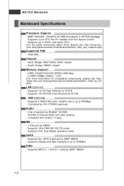
Supports up to 400Mbps - South Bridge: SB600 chipset Memory Support - Flexible 8-channel audio with Fan Speed Control - Supports 4 pin CPU Fan Pin-Header with jack sensing - php) LAN (Optional) - Supports 10/100 Fast Ethernet by VIA VT6308 (optional) Audio - Controlled....tw/program/products/mainboard/mbd/pro_mbd_trp_list. Supports storage and data transfers at up to 5000+ and higter CPU (For the latest inform ation about CPU, please visit http://www.msi. Supports RAID 0, 1 and 0+1 mode by AMD® SB600 1-2 North Bridge: AMD® 690G/ 690V chipset - Supports PIO, ...
Supports up to 400Mbps - South Bridge: SB600 chipset Memory Support - Flexible 8-channel audio with Fan Speed Control - Supports 4 pin CPU Fan Pin-Header with jack sensing - php) LAN (Optional) - Supports 10/100 Fast Ethernet by VIA VT6308 (optional) Audio - Controlled....tw/program/products/mainboard/mbd/pro_mbd_trp_list. Supports storage and data transfers at up to 5000+ and higter CPU (For the latest inform ation about CPU, please visit http://www.msi. Supports RAID 0, 1 and 0+1 mode by AMD® SB600 1-2 North Bridge: AMD® 690G/ 690V chipset - Supports PIO, ...
User Guide
Page 18
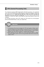
... CPU, please visit http://www.msi.com.tw/program/ products/mainboard/mbd/pro_mbd_cpu_support.php Important 1. Make sure that you apply an even layer of heat sink paste (or thermal tape) between the CPU and the heatsink to ensure the safety of CPU. 2-3 While replacing the CPU, always turn off the ATX ...power supply or unplug the power supply's power cord from overheating. 2. Always make sure the CPU has a heat sink and a cooling fan attached ...
... CPU, please visit http://www.msi.com.tw/program/ products/mainboard/mbd/pro_mbd_cpu_support.php Important 1. Make sure that you apply an even layer of heat sink paste (or thermal tape) between the CPU and the heatsink to ensure the safety of CPU. 2-3 While replacing the CPU, always turn off the ATX ...power supply or unplug the power supply's power cord from overheating. 2. Always make sure the CPU has a heat sink and a cooling fan attached ...
User Guide
Page 19
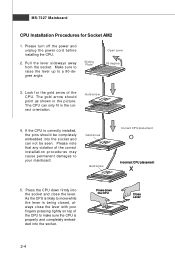
...pins should point as shown in the correct orientation. Sliding Plate Open Lever 90 degree 3. The gold arrow should be seen. Press the CPU down firmly into the socket and close the lever with your mainboard. Please turn off the power and unplug the power cord before installing ...the CPU. 2. Look for Socket AM2 1. Gold arrow 4. Please note that any violation of the correct installation procedures may cause permanent damages to a 90-...
...pins should point as shown in the correct orientation. Sliding Plate Open Lever 90 degree 3. The gold arrow should be seen. Press the CPU down firmly into the socket and close the lever with your mainboard. Please turn off the power and unplug the power cord before installing ...the CPU. 2. Look for Socket AM2 1. Gold arrow 4. Please note that any violation of the correct installation procedures may cause permanent damages to a 90-...
User Guide
Page 20
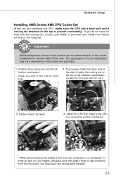
... down the lever. 4. Fasten down the other end of the clip to fasten the cooling set onto the retention mechanism. Attach the CPU Fan cable to the CPU fan connector on the mainboard. * While disconnecting the Safety Hook from the fixed bolt, it . Fixed Lever 3. Important Mainboard photos... shown in this section are installing the CPU, make sure the CPU has a heat sink and a cooling fan attached on the top to hook first. 2. Hook one end of the cooler installation for ...
... down the lever. 4. Fasten down the other end of the clip to fasten the cooling set onto the retention mechanism. Attach the CPU Fan cable to the CPU fan connector on the mainboard. * While disconnecting the Safety Hook from the fixed bolt, it . Fixed Lever 3. Important Mainboard photos... shown in this section are installing the CPU, make sure the CPU has a heat sink and a cooling fan attached on the top to hook first. 2. Hook one end of the cooler installation for ...

User Guide
Page 23
...12, 23 & 24 to use the 20-pin ATX power supply as you 'd like . You may use the 20-pin ATX power supply, please plug your power sup- MS-7327 Mainboard Power Supply ATX 24-Pin Power Connector: ATX1 This connector allows you to the CPU. JPW1 4 2 3 1 JPW1 Pin Definition PIN ...SIGNAL 1 GND 2 GND 3 12V 4 12V Important 1. If you like to avoid wrong installation. There is used to provide power to connect an ATX 24-pin power supply. Maker sure that all the...
...12, 23 & 24 to use the 20-pin ATX power supply as you 'd like . You may use the 20-pin ATX power supply, please plug your power sup- MS-7327 Mainboard Power Supply ATX 24-Pin Power Connector: ATX1 This connector allows you to the CPU. JPW1 4 2 3 1 JPW1 Pin Definition PIN ...SIGNAL 1 GND 2 GND 3 12V 4 12V Important 1. If you like to avoid wrong installation. There is used to provide power to connect an ATX 24-pin power supply. Maker sure that all the...
User Guide
Page 28
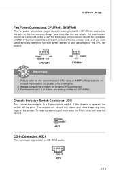
..., the switch will record this status and show a warning message on tr ol . Fan/heatsink with 3 or 4 pins are both available for proper CPU cooling fan. 2. Chassis Intrusion Switch Connector: JCI1 This connector connects to a 2-pin chassis switch. The system will be connected to GND. L GND ...-board, you must use a specially designed fan with +12V. W hen connecting the wire to the connectors, always take advantage of the CPU fan c on the screen. Hardware Setup Fan Power Connectors: CPUFAN1, SYSFAN1 The fan power connectors support system cooling fan with speed sensor to...
..., the switch will record this status and show a warning message on tr ol . Fan/heatsink with 3 or 4 pins are both available for proper CPU cooling fan. 2. Chassis Intrusion Switch Connector: JCI1 This connector connects to a 2-pin chassis switch. The system will be connected to GND. L GND ...-board, you must use a specially designed fan with +12V. W hen connecting the wire to the connectors, always take advantage of the CPU fan c on the screen. Hardware Setup Fan Power Connectors: CPUFAN1, SYSFAN1 The fan power connectors support system cooling fan with speed sensor to...
User Guide
Page 44
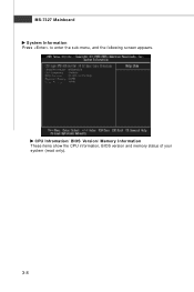
CPU Infromation/ BIOS Version/ M emory Information These items show the CPU information, BIOS version and memory status of your system (read only). 3-8 MS-7327 Mainboard System Information Press to enter the sub-menu, and the following screen appears.
CPU Infromation/ BIOS Version/ M emory Information These items show the CPU information, BIOS version and memory status of your system (read only). 3-8 MS-7327 Mainboard System Information Press to enter the sub-menu, and the following screen appears.
User Guide
Page 51
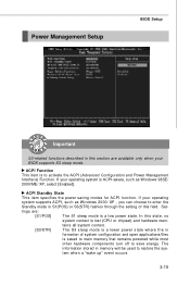
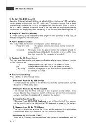
... are: [S1/POS] The S1 sleep mode is a lower power state where the in this section are available only when your operating system is lost (CPU or chipset) and hardware main- ACPI Function This item is saved to main memory that remains powered while most other hardware components turn off to...
... are: [S1/POS] The S1 sleep mode is a lower power state where the in this section are available only when your operating system is lost (CPU or chipset) and hardware main- ACPI Function This item is saved to main memory that remains powered while most other hardware components turn off to...
User Guide
Page 52
... State] Restores the system to initialize the VGA card. Resume by PCI Device (PME#) W hen set the specific key in this field, all devices except CPU will need an AGP driver to the status before power failure or interrupt occurred. Therefore, if the AGP driver of the power button. Settings are...
... State] Restores the system to initialize the VGA card. Resume by PCI Device (PME#) W hen set the specific key in this field, all devices except CPU will need an AGP driver to the status before power failure or interrupt occurred. Therefore, if the AGP driver of the power button. Settings are...
User Guide
Page 54
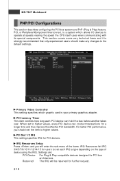
... primary graphics adapter. Primary Video Controller This setting specifies which graphic card is a system which allows I/O devices to operate at speeds nearing the speed the CPU itself uses when communicating with its special components. For better PCI performance, you will be reserved for a longer time and thus improve the effective PCI...
... primary graphics adapter. Primary Video Controller This setting specifies which graphic card is a system which allows I/O devices to operate at speeds nearing the speed the CPU itself uses when communicating with its special components. For better PCI performance, you will be reserved for a longer time and thus improve the effective PCI...
User Guide
Page 56
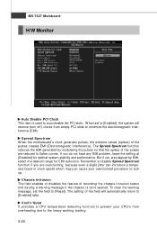
...system stability and performance. Remember to disable Spread Spectrum function if you are reduced to flatter curves. Cool'n'Quiet It provides a CPU temperature detecting function to prevent your overclocked processor to [Reset]. W hen set the field to lock up. Chassis Intrusion The field... to [Enabled] later. MS-7327 Mainboard H/W Monitor Auto Disable PCI Clock This item is once opened. Spread Spectrum W hen the motherboard's clock generator pulses, the extreme values (spikes) of recording the chassis intrusion status and issuing a warning message if the chassis is used...
...system stability and performance. Remember to disable Spread Spectrum function if you are reduced to flatter curves. Cool'n'Quiet It provides a CPU temperature detecting function to prevent your overclocked processor to [Reset]. W hen set the field to lock up. Chassis Intrusion The field... to [Enabled] later. MS-7327 Mainboard H/W Monitor Auto Disable PCI Clock This item is once opened. Spread Spectrum W hen the motherboard's clock generator pulses, the extreme values (spikes) of recording the chassis intrusion status and issuing a warning message if the chassis is used...

User Guide
Page 57
...fan will speed up for the "Smart Fan Target Temp. (oC)" item. FAN Speed (%) This item allows you p ur c h as CPU voltage, temperatures and all fans' speeds. 3-21 CPU FAN PIN Select Be sure to select the correct pin number identical to the pin of the monitored hardware devices/ components such... as e. Smart Fan Tolerance You can control the fan speed automatically depending on the current temperature to keep the temperature stable. CPU/System Temperature, CPU FAN/ SYSTEM FAN Speed, CPU Vcore, 3.3VCC, 5V, 12V, 3.3V SB These items display the current status of all of the...
...fan will speed up for the "Smart Fan Target Temp. (oC)" item. FAN Speed (%) This item allows you p ur c h as CPU voltage, temperatures and all fans' speeds. 3-21 CPU FAN PIN Select Be sure to select the correct pin number identical to the pin of the monitored hardware devices/ components such... as e. Smart Fan Tolerance You can control the fan speed automatically depending on the current temperature to keep the temperature stable. CPU/System Temperature, CPU FAN/ SYSTEM FAN Speed, CPU Vcore, 3.3VCC, 5V, 12V, 3.3V SB These items display the current status of all of the...

