
User Guide
Page 8
... Socket AM2 CPU Cooler Set 2-5 Memory ...2-6 Memory Module Population Rules 2-6 Installing DDRII Modules 2-7 Power Supply ...2-8 ATX 24-Pin Power Connector: ATX1 2-8 ATX 12V Power Connector: JPW 1 2-8 Back Panel ...2-9 Connectors ...2-11 Floppy Disk Drive Connector: FDD1 2-11 ATA133...14 Front USB Connectors: JUSB1, JUSB2 & JUSB3 2-15 TV-Out Connector: JTV1 (Optional 2-16 IEEE 1394 Connectors: J1394_1 2-17 SPDIF-Out / SPDIF-In Connector: SPDOUT1 / SPDIN1 (Optional 2-18 viii Getting Started 1-1 Mainboard Specifications 1-2 Mainboard Layout 1-4 Packing Checklist 1-4 Setup audio output...
... Socket AM2 CPU Cooler Set 2-5 Memory ...2-6 Memory Module Population Rules 2-6 Installing DDRII Modules 2-7 Power Supply ...2-8 ATX 24-Pin Power Connector: ATX1 2-8 ATX 12V Power Connector: JPW 1 2-8 Back Panel ...2-9 Connectors ...2-11 Floppy Disk Drive Connector: FDD1 2-11 ATA133...14 Front USB Connectors: JUSB1, JUSB2 & JUSB3 2-15 TV-Out Connector: JTV1 (Optional 2-16 IEEE 1394 Connectors: J1394_1 2-17 SPDIF-Out / SPDIF-In Connector: SPDOUT1 / SPDIN1 (Optional 2-18 viii Getting Started 1-1 Mainboard Specifications 1-2 Mainboard Layout 1-4 Packing Checklist 1-4 Setup audio output...
User Guide
Page 12
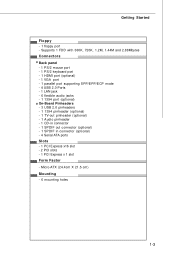
Micro-ATX (24.4cm X 21.5 cm) Mounting - 6 mounting holes 1-3 Supports 1 FDD with 360K, 720K, 1.2M, 1.44M and 2.88Mbytes Connectors Back panel - 1 PS/2 mouse port - 1 PS/2 keyboard port -...- 6 flexible audio jacks - 1 1394 port (optional) On-Board Pinheaders - 3 USB 2.0 pinheaders - 1 1394 pinheader (optional) - 1 TV-out pinheader (optional) - 1 Audio pinheader - 1 CD-in connector - 1 SPDIF out connector (optional) - 1 SPDIF in connector (optional) - 4 Serial ATA ports Slots - 1 PCI Express x16 slot - 2 PCI slots - 1 PCI Express x 1 slot Form Factor - Getting Started Floppy - 1 floppy port -
Micro-ATX (24.4cm X 21.5 cm) Mounting - 6 mounting holes 1-3 Supports 1 FDD with 360K, 720K, 1.2M, 1.44M and 2.88Mbytes Connectors Back panel - 1 PS/2 mouse port - 1 PS/2 keyboard port -...- 6 flexible audio jacks - 1 1394 port (optional) On-Board Pinheaders - 3 USB 2.0 pinheaders - 1 1394 pinheader (optional) - 1 TV-out pinheader (optional) - 1 Audio pinheader - 1 CD-in connector - 1 SPDIF out connector (optional) - 1 SPDIF in connector (optional) - 4 Serial ATA ports Slots - 1 PCI Express x16 slot - 2 PCI slots - 1 PCI Express x 1 slot Form Factor - Getting Started Floppy - 1 floppy port -
User Guide
Page 33
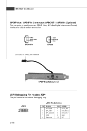
JSPI1 9 1 10 2 JSPI1 Pin Definition PIN SIGNAL 1 VCC3_SB 3 SPI_MISO 5 SPI_CSO_F# 7 GND 9 Reserved PIN SIGNAL 2 VCC3_SB 4 SPI_MOSI_F 6 SPI_CLK_F 8 GND 10 NC 2-18 GND SPDIF OUT VCC SPDOUT1 GND SPDIF IN VCC SPDIN1 Connected to SPDOUT1 / SPDIN1 SPDIF Bracket (Optional) JSPI Debugging Pin Header: JSPI1 The pin header is used to connect SPDIF (Sony & Philips Digital Interconnect Format) interface for internal debugging only. MS-7327 Mainboard SPDIF-Out / SPDIF-In Connector: SPDOUT1 / SPDIN1 (Optional) This connector is for digital audio transmission.
JSPI1 9 1 10 2 JSPI1 Pin Definition PIN SIGNAL 1 VCC3_SB 3 SPI_MISO 5 SPI_CSO_F# 7 GND 9 Reserved PIN SIGNAL 2 VCC3_SB 4 SPI_MOSI_F 6 SPI_CLK_F 8 GND 10 NC 2-18 GND SPDIF OUT VCC SPDOUT1 GND SPDIF IN VCC SPDIN1 Connected to SPDOUT1 / SPDIN1 SPDIF Bracket (Optional) JSPI Debugging Pin Header: JSPI1 The pin header is used to connect SPDIF (Sony & Philips Digital Interconnect Format) interface for internal debugging only. MS-7327 Mainboard SPDIF-Out / SPDIF-In Connector: SPDOUT1 / SPDIN1 (Optional) This connector is for digital audio transmission.