User Guide
Page 2
Notice 1 The changes or modifications not expressly approved by the party responsible for a class B digital device, pursuant to part 15 of this equipment in a residential area is operated in a commercial environment. Manual Rev: 1.0 Release Date: September 2003 FCC-B Radio Frequency Interference Statement This equipment has been tested and found to comply with the limits for compliance could void the user's authority to operate the equipment. VOIR LA NOTICE D'INSTALLATION AVANT DE RACCORDER AU RESEAU. This equipment generates, uses and can radiate radio frequency energy and, if not ...
Notice 1 The changes or modifications not expressly approved by the party responsible for a class B digital device, pursuant to part 15 of this equipment in a residential area is operated in a commercial environment. Manual Rev: 1.0 Release Date: September 2003 FCC-B Radio Frequency Interference Statement This equipment has been tested and found to comply with the limits for compliance could void the user's authority to operate the equipment. VOIR LA NOTICE D'INSTALLATION AVANT DE RACCORDER AU RESEAU. This equipment generates, uses and can radiate radio frequency energy and, if not ...
User Guide
Page 3
..., please try the following help resources for FAQ, technical guide, BIOS updates, driver updates, and other information: http://www.msi.com.tw/ Contact our technical staff at: support@msi.com.tw iii Copyright Notice The material in the preparation of this document is given as to make changes without notice.... Visit the MSI website for further guidance. We take every care in this document, but no solution can be obtained from the user's manual, please contact...
..., please try the following help resources for FAQ, technical guide, BIOS updates, driver updates, and other information: http://www.msi.com.tw/ Contact our technical staff at: support@msi.com.tw iii Copyright Notice The material in the preparation of this document is given as to make changes without notice.... Visit the MSI website for further guidance. We take every care in this document, but no solution can be obtained from the user's manual, please contact...
User Guide
Page 4
Keep this User's Manual for air convection hence protects the equipment from humidity. 4. DO NOT COVER THE OPENINGS. 6. Place the power cord such a way that could damage or cause electri- z Liquid has penetrated into the opening that people can not get the equipment checked by the manufacturer. z The equipment has been exposed to the power inlet. 7. iv Lay this equipment away from overheating. Never pour any liquid into the equipment. z The equipment has not work according to User's Manual. Keep this equipment on it work well or you can not step on a ...
Keep this User's Manual for air convection hence protects the equipment from humidity. 4. DO NOT COVER THE OPENINGS. 6. Place the power cord such a way that could damage or cause electri- z Liquid has penetrated into the opening that people can not get the equipment checked by the manufacturer. z The equipment has been exposed to the power inlet. 7. iv Lay this equipment away from overheating. Never pour any liquid into the equipment. z The equipment has not work according to User's Manual. Keep this equipment on it work well or you can not step on a ...
User Guide
Page 5
... Combination List 2-11 Power Supply 2-12 ATX 20-Pin Power Connector: ATX 2-12 ATX 12V Power Connector: JPW1 2-12 v Getting Started 1-1 Mainboard Specifications 1-2 Mainboard Layout 1-4 MSI Special Features 1-5 Color Management 1-5 Core Center 1-6 Core Cell™ Chip 1-9 Dynamic Overclocking Technology 1-10 Live BIOS™/Live Driver 1-11 Live Monitor 1-12 D-Bracket™...
... Combination List 2-11 Power Supply 2-12 ATX 20-Pin Power Connector: ATX 2-12 ATX 12V Power Connector: JPW1 2-12 v Getting Started 1-1 Mainboard Specifications 1-2 Mainboard Layout 1-4 MSI Special Features 1-5 Color Management 1-5 Core Center 1-6 Core Cell™ Chip 1-9 Dynamic Overclocking Technology 1-10 Live BIOS™/Live Driver 1-11 Live Monitor 1-12 D-Bracket™...
User Guide
Page 6
Back Panel 2-13 Mouse Connector 2-13 Keyboard Connector 2-13 USB 2.0 Connectors 2-14 IEEE1394 Ports (Optional 2-14 Serial Port Connector: COM A 2-15 RJ-45 LAN Jack (Optional 2-15 Audio Port Connectors 2-16 Parallel Port Connector: LPT1 2-17 Connectors 2-18 Floppy Disk Drive Connector: FDD1 2-18 IrDA Infrared Module Header: JIR1 2-18 Chassis Intrusion Switch Connector: JCASE1 2-18 Fan Power Connectors: CFAN1/SFAN1/PWFAN1/PWFAN2 ..... 2-19 Front USB Connectors: JUSB1/JUSB2 2-19 Front Panel Connectors: JFP1 & JFP2 2-20 CD-In Connector: J4 2-20 Hard Disk Connectors: IDE1 & IDE2 2-...
Back Panel 2-13 Mouse Connector 2-13 Keyboard Connector 2-13 USB 2.0 Connectors 2-14 IEEE1394 Ports (Optional 2-14 Serial Port Connector: COM A 2-15 RJ-45 LAN Jack (Optional 2-15 Audio Port Connectors 2-16 Parallel Port Connector: LPT1 2-17 Connectors 2-18 Floppy Disk Drive Connector: FDD1 2-18 IrDA Infrared Module Header: JIR1 2-18 Chassis Intrusion Switch Connector: JCASE1 2-18 Fan Power Connectors: CFAN1/SFAN1/PWFAN1/PWFAN2 ..... 2-19 Front USB Connectors: JUSB1/JUSB2 2-19 Front Panel Connectors: JFP1 & JFP2 2-20 CD-In Connector: J4 2-20 Hard Disk Connectors: IDE1 & IDE2 2-...
User Guide
Page 7
Using 4- VIA VT8237 Serial ATA RAID Introduction B-1 vii or 6-Channel Audio Function A-1 AppendixB. BIOS Setup 3-1 Entering Setup 3-2 Selecting the First Boot Device 3-2 Control Keys 3-3 Getting Help 3-3 The Main Menu 3-4 Standard CMOS Features 3-6 Advanced BIOS Features 3-8 Advanced Chipset Features 3-12 Power Management Features 3-15 PNP/PCI Configurations 3-19 Integrated Peripherals 3-21 PC Health Status 3-24 Frequency/Voltage Control 3-25 Set Supervisor/User Password 3-27 Load High Performance/BIOS Setup Defaults 3-28 AppendixA. Chapter 3.
Using 4- VIA VT8237 Serial ATA RAID Introduction B-1 vii or 6-Channel Audio Function A-1 AppendixB. BIOS Setup 3-1 Entering Setup 3-2 Selecting the First Boot Device 3-2 Control Keys 3-3 Getting Help 3-3 The Main Menu 3-4 Standard CMOS Features 3-6 Advanced BIOS Features 3-8 Advanced Chipset Features 3-12 Power Management Features 3-15 PNP/PCI Configurations 3-19 Integrated Peripherals 3-21 PC Health Status 3-24 Frequency/Voltage Control 3-25 Set Supervisor/User Password 3-27 Load High Performance/BIOS Setup Defaults 3-28 AppendixA. Chapter 3.

User Guide
Page 8
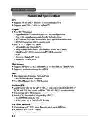
The K8T Neo is based on VIA® K8T800 North Bridge & VT8237 South Bridge chipsets and provides eight USB 2.0 ports for high-speed data transmission, RealTek ALC655 chip for 6-channel audio output, and a SPDIF interface for purchasing K8T Neo (MS-6702 v1.X) ATX mainboard. Getting Started Getting Started Thank you for digital audio transmission. Getting Started Chapter 1. Designed to fit the advanced AMD® Athlon64 processors, the K8T Neo delivers a high performance and professional desktop platform solution. 1-1
The K8T Neo is based on VIA® K8T800 North Bridge & VT8237 South Bridge chipsets and provides eight USB 2.0 ports for high-speed data transmission, RealTek ALC655 chip for 6-channel audio output, and a SPDIF interface for purchasing K8T Neo (MS-6702 v1.X) ATX mainboard. Getting Started Getting Started Thank you for digital audio transmission. Getting Started Chapter 1. Designed to fit the advanced AMD® Athlon64 processors, the K8T Neo delivers a high performance and professional desktop platform solution. 1-1
User Guide
Page 9
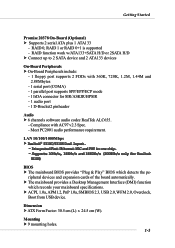
... Graphics Port) AGP slot. - Can connect up to 2 serial ATA devices IEEE 1394 (Optional) h Supports up to 3200+, 3400+, or higher CPU Chipset h VIA® K8T800 chipset - Transfer rate is up to AMD Athlon64 processor - 8 or 16 bit control/address/data transfer both directions - 800/600/400/200 MHz "Double Data...
... Graphics Port) AGP slot. - Can connect up to 2 serial ATA devices IEEE 1394 (Optional) h Supports up to 3200+, 3400+, or higher CPU Chipset h VIA® K8T800 chipset - Transfer rate is up to AMD Athlon64 processor - 8 or 16 bit control/address/data transfer both directions - 800/600/400/200 MHz "Double Data...
User Guide
Page 10
RAID 0, RAID 1 or RAID 0+1 is supported - Compliance with 360K, 720K, 1.2M, 1.44M and 2.88Mbytes - 1 serial port (COMA) - 1 parallel port supports SPP/EPP/ECP mode - 1 IrDA connector for SIR/ASKIR/HPSIR - 1 audio port - 1 D-Bracket2 pinheader Audio h 6 channels software audio codec RealTek ALC655. - Meet PC2001 audio performance requirement. h The mainboard provides a Desktop Management Interface (DMI) function which detects the pe- Mounting h 9 mounting holes. 1-3 LAN 10/100/1000Mbps h RReeaalltteekk®® 88111100CC//88111100SSDDuuaallllaayyoouutt.. --...
RAID 0, RAID 1 or RAID 0+1 is supported - Compliance with 360K, 720K, 1.2M, 1.44M and 2.88Mbytes - 1 serial port (COMA) - 1 parallel port supports SPP/EPP/ECP mode - 1 IrDA connector for SIR/ASKIR/HPSIR - 1 audio port - 1 D-Bracket2 pinheader Audio h 6 channels software audio codec RealTek ALC655. - Meet PC2001 audio performance requirement. h The mainboard provides a Desktop Management Interface (DMI) function which detects the pe- Mounting h 9 mounting holes. 1-3 LAN 10/100/1000Mbps h RReeaalltteekk®® 88111100CC//88111100SSDDuuaallllaayyoouutt.. --...
User Guide
Page 11
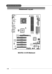
O u t M:Line-Out B:SPDIF Out JPW1 VIA K8T800 SFAN1 DDR 1 DDR 2 DDR 3 IDE 1 IDE 2 FDD 1 VIA VT6307 R e al Te k 8 110 S J4 Codec JAUD1 AGP Slot PCI Slot 1 PCI Slot 2 PCI Slot 3 PCI Slot 4 ...
O u t M:Line-Out B:SPDIF Out JPW1 VIA K8T800 SFAN1 DDR 1 DDR 2 DDR 3 IDE 1 IDE 2 FDD 1 VIA VT6307 R e al Te k 8 110 S J4 Codec JAUD1 AGP Slot PCI Slot 1 PCI Slot 2 PCI Slot 3 PCI Slot 4 ...
User Guide
Page 12
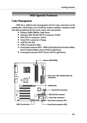
... Switch in Blue, Power Switch in Black, Power LED in Light Green. h Front panel connector JFP2: Power LED in Light Green. Getting Started MSI Special Features Color Management MSI has a unified color management rule for some connectors on the mainboards, which helps you to install the memory modules, expansion cards and other...
... Switch in Blue, Power Switch in Black, Power LED in Light Green. h Front panel connector JFP2: Power LED in Light Green. Getting Started MSI Special Features Color Management MSI has a unified color management rule for some connectors on the mainboards, which helps you to install the memory modules, expansion cards and other...
User Guide
Page 13
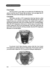
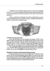
The utility is a new utility you will be capable of detecting the temperature of the system cooling fan will be able to adjust the CPU fan speed by sliding the adjusting bar. 1-6 Cool'n'Quiet is selected, you can detect, view and adjust the PC hardware and system status during real time operation. When the CPU temperature climbs up to a certain degree, the speed of the CPU according to its normal degree. To activate Cool'n'Quiet function, please click the Core Center Cool'n'Quiet icon, and then select Cool'n'Quiet mode. Cool'n'Quiet This utility provides a CPU temperature ...
The utility is a new utility you will be capable of detecting the temperature of the system cooling fan will be able to adjust the CPU fan speed by sliding the adjusting bar. 1-6 Cool'n'Quiet is selected, you can detect, view and adjust the PC hardware and system status during real time operation. When the CPU temperature climbs up to a certain degree, the speed of the CPU according to its normal degree. To activate Cool'n'Quiet function, please click the Core Center Cool'n'Quiet icon, and then select Cool'n'Quiet mode. Cool'n'Quiet This utility provides a CPU temperature ...
User Guide
Page 14
Left-side: Current system status In the left sub-menu, you may click Default to restore the default values. Or you can configure the settings of FSB, Vcore, Memory Voltage and AGP Voltage by clicking the radio button in the left and right sides. You may click Auto to start testing the maximal CPU overclocking value, The CPU FSB will automatically increase the testing value until the PC reboots. Right-side: PC hardware status during real time operation In the right sub-menu, here you set for the temperatures are the minimum thresholds. 1-7 The values you can click Save to ...
Left-side: Current system status In the left sub-menu, you may click Default to restore the default values. Or you can configure the settings of FSB, Vcore, Memory Voltage and AGP Voltage by clicking the radio button in the left and right sides. You may click Auto to start testing the maximal CPU overclocking value, The CPU FSB will automatically increase the testing value until the PC reboots. Right-side: PC hardware status during real time operation In the right sub-menu, here you set for the temperatures are the minimum thresholds. 1-7 The values you can click Save to ...
User Guide
Page 15
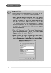
.... On the top of CPU, there are three lines listed under Power schemes. 1-8 Run BIOS Setup, and select Frequency/Voltage Control. MS-6702 ATX Mainboard MSI Reminds You... Check the serial number printed on ), that means this CPU does not support Cool'n'Quiet function. 2. If the last character is required to...
.... On the top of CPU, there are three lines listed under Power schemes. 1-8 Run BIOS Setup, and select Frequency/Voltage Control. MS-6702 ATX Mainboard MSI Reminds You... Check the serial number printed on ), that means this CPU does not support Cool'n'Quiet function. 2. If the last character is required to...
User Guide
Page 16
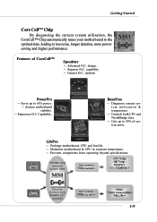
Superior O.C. Greater O.C. Controls both CPU and NorthBridge fans. -- Maintains motherboard & CPU in constant temperature. -- Advanced O.C. capability. -- Empowers O.C Capability. BuzzFree -- Cuts up to 65% power. -- method. Diagnoses current system ...beyond specifications. 1-9 Saves up to less noise, longer duration, more powersaving and higher performance. Features of system noise. Assures motherboard stability. -- design. -- LifePro -- Getting Started Core CellTM Chip By diagnosing the current system utilization, the CoreCell™ Chip automatically tunes your...
Superior O.C. Greater O.C. Controls both CPU and NorthBridge fans. -- Maintains motherboard & CPU in constant temperature. -- Advanced O.C. capability. -- Empowers O.C Capability. BuzzFree -- Cuts up to 65% power. -- method. Diagnoses current system ...beyond specifications. 1-9 Saves up to less noise, longer duration, more powersaving and higher performance. Features of system noise. Assures motherboard stability. -- design. -- LifePro -- Getting Started Core CellTM Chip By diagnosing the current system utilization, the CoreCell™ Chip automatically tunes your...
User Guide
Page 17
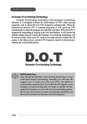
..., it will be boosted up CPU automatically to make sure that your CPU can afford to run smoothly and faster. When the motherboard detects CPU is running programs, and to adjust the best CPU frequency automatically. MS-6702 ATX Mainboard Dynamic Overclocking Technology Dynamic Overclocking ... and the CPU frequency need to disable the Dynamic OverClocking first. 1-10 It is the automatic overclocking function. D.O.T Dynamic Overclocking Technology MSI Reminds You... When the CPU is still risky. If you also need to be powered only when users' PC need to overclocking regularly ...
..., it will be boosted up CPU automatically to make sure that your CPU can afford to run smoothly and faster. When the motherboard detects CPU is running programs, and to adjust the best CPU frequency automatically. MS-6702 ATX Mainboard Dynamic Overclocking Technology Dynamic Overclocking ... and the CPU frequency need to disable the Dynamic OverClocking first. 1-10 It is the automatic overclocking function. D.O.T Dynamic Overclocking Technology MSI Reminds You... When the CPU is still risky. If you also need to be powered only when users' PC need to overclocking regularly ...
User Guide
Page 18
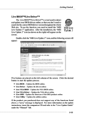
...BIOS/drivers online so that you need to start the update process. Ø Live BIOS - Updates the utilities online. After the installation, the "MSI Live Update 3" icon (as shown on the right) will appear: Five buttons are placed on the update instructions, insert the companion CD and ...refer to install the "MSI Live Update 3" application. Updates the BIOS online. Ø Live Driver - Getting Started Live BIOS™/Live Driver™ The Live BIOS™/Live...
...BIOS/drivers online so that you need to start the update process. Ø Live BIOS - Updates the utilities online. After the installation, the "MSI Live Update 3" icon (as shown on the right) will appear: Five buttons are placed on the update instructions, insert the companion CD and ...refer to install the "MSI Live Update 3" application. Updates the BIOS online. Ø Live Driver - Getting Started Live BIOS™/Live Driver™ The Live BIOS™/Live...
User Guide
Page 19
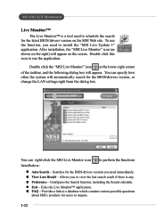
...you to view the last search result if there is a tool used to perform the functions listed below: z Auto Search - You can right-click the MSI Live Monitor icon to schedule the search for the latest BIOS/drivers version on the screen. z View Last Result - Allows you need to inquire. 1-12... Configures the Search function, including the Search schedule. z FAQ - Double click the "MSI Live Monitor" icon at the lower-right corner of the taskbar, and the following dialog box will appear on the...
...you to view the last search result if there is a tool used to perform the functions listed below: z Auto Search - You can right-click the MSI Live Monitor icon to schedule the search for the latest BIOS/drivers version on the screen. z View Last Result - Allows you need to inquire. 1-12... Configures the Search function, including the Search schedule. z FAQ - Double click the "MSI Live Monitor" icon at the lower-right corner of the taskbar, and the following dialog box will appear on the...
User Guide
Page 20
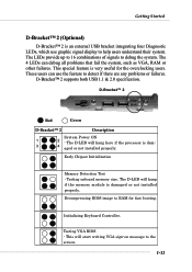
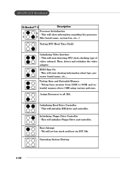
D-Bracket™ 2 supports both USB 1.1 & 2.0 specification. The D-LED will hang if the memory module is damaged or not installed properly. The D-LED will hang here if the processor is dam- 3 4 aged or not installed properly. Testing onboard memory size. This will start writing VGA sign-on message to detect if there are any problems or failures. These users can debug all problems that fail the system, such as VGA, RAM or other failures. Early Chipset Initialization Memory Detection Test - Decompressing BIOS image to help users understand their system. Initializing ...
D-Bracket™ 2 supports both USB 1.1 & 2.0 specification. The D-LED will hang if the memory module is damaged or not installed properly. The D-LED will hang here if the processor is dam- 3 4 aged or not installed properly. Testing onboard memory size. This will start writing VGA sign-on message to detect if there are any problems or failures. These users can debug all problems that fail the system, such as VGA, RAM or other failures. Early Chipset Initialization Memory Detection Test - Decompressing BIOS image to help users understand their system. Initializing ...
User Guide
Page 21
Assign Resources to 640K and extended memory above 1MB using various patterns. Initializing Hard Drive Controller - Then, detect and initialize the video adapter. This will start showing information about logo, processor brand name, etc... Boot Attempt - Testing Base and Extended Memory - Operating System Booting 1-14 This will initialize IDE drive and controller. This will set low stack and boot via INT 19h. Teting base memory from 240K to all ISA. Thi will initialize Floppy Drive and controller. This will show information regarding the processor 3 4 (...
Assign Resources to 640K and extended memory above 1MB using various patterns. Initializing Hard Drive Controller - Then, detect and initialize the video adapter. This will start showing information about logo, processor brand name, etc... Boot Attempt - Testing Base and Extended Memory - Operating System Booting 1-14 This will initialize IDE drive and controller. This will set low stack and boot via INT 19h. Teting base memory from 240K to all ISA. Thi will initialize Floppy Drive and controller. This will show information regarding the processor 3 4 (...