User Guide
Page 7
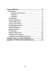
Using 4- or 6-Channel Audio Function A-1 AppendixB. Chapter 3. VIA VT8237 Serial ATA RAID Introduction B-1 vii BIOS Setup 3-1 Entering Setup 3-2 Selecting the First Boot Device 3-2 Control Keys 3-3 Getting Help 3-3 The Main Menu 3-4 Standard CMOS Features 3-6 Advanced BIOS Features 3-8 Advanced Chipset Features 3-12 Power Management Features 3-15 PNP/PCI Configurations 3-19 Integrated Peripherals 3-21 PC Health Status 3-24 Frequency/Voltage Control 3-25 Set Supervisor/User Password 3-27 Load High Performance/BIOS Setup Defaults 3-28 AppendixA.
Using 4- or 6-Channel Audio Function A-1 AppendixB. Chapter 3. VIA VT8237 Serial ATA RAID Introduction B-1 vii BIOS Setup 3-1 Entering Setup 3-2 Selecting the First Boot Device 3-2 Control Keys 3-3 Getting Help 3-3 The Main Menu 3-4 Standard CMOS Features 3-6 Advanced BIOS Features 3-8 Advanced Chipset Features 3-12 Power Management Features 3-15 PNP/PCI Configurations 3-19 Integrated Peripherals 3-21 PC Health Status 3-24 Frequency/Voltage Control 3-25 Set Supervisor/User Password 3-27 Load High Performance/BIOS Setup Defaults 3-28 AppendixA.
User Guide
Page 8
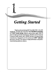
Getting Started Getting Started Thank you for digital audio transmission. Designed to fit the advanced AMD® Athlon64 processors, the K8T Neo delivers a high performance and professional desktop platform solution. 1-1 Getting Started Chapter 1. The K8T Neo is based on VIA® K8T800 North Bridge & VT8237 South Bridge chipsets and provides eight USB 2.0 ports for high-speed data transmission, RealTek ALC655 chip for 6-channel audio output, and a SPDIF interface for purchasing K8T Neo (MS-6702 v1.X) ATX mainboard.
Getting Started Getting Started Thank you for digital audio transmission. Designed to fit the advanced AMD® Athlon64 processors, the K8T Neo delivers a high performance and professional desktop platform solution. 1-1 Getting Started Chapter 1. The K8T Neo is based on VIA® K8T800 North Bridge & VT8237 South Bridge chipsets and provides eight USB 2.0 ports for high-speed data transmission, RealTek ALC655 chip for 6-channel audio output, and a SPDIF interface for purchasing K8T Neo (MS-6702 v1.X) ATX mainboard.
User Guide
Page 9
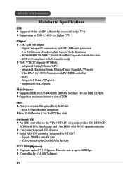
...Specifications CPU h Supports 64-bit AMD® Athlon64 processor (Socket 754) h Supports up to 4 IDE devices h Serial ATA/150 controller integrated by VIA 6307 chipset 1-2 Integrated Hardware Sound Blaster/Direct Sound AC97 audio - Supports 2 Serial ATA ports - AGP v3.0 compliant with PIO, Bus Master and Ultra DMA 66/100/.../data transfer both directions - 800/600/400/200 MHz "Double Data Rate" operation both direction - ROM with 8x transfer mode h VIA® VT8237 chipset (487 BGA) - HyperTransportTM connection to 3200+, 3400+, or higher CPU Chipset h VIA® K8T800 chipset -
...Specifications CPU h Supports 64-bit AMD® Athlon64 processor (Socket 754) h Supports up to 4 IDE devices h Serial ATA/150 controller integrated by VIA 6307 chipset 1-2 Integrated Hardware Sound Blaster/Direct Sound AC97 audio - Supports 2 Serial ATA ports - AGP v3.0 compliant with PIO, Bus Master and Ultra DMA 66/100/.../data transfer both directions - 800/600/400/200 MHz "Double Data Rate" operation both direction - ROM with 8x transfer mode h VIA® VT8237 chipset (487 BGA) - HyperTransportTM connection to 3200+, 3400+, or higher CPU Chipset h VIA® K8T800 chipset -
User Guide
Page 20
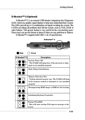
... memory module is dam- 3 4 aged or not installed properly. Decompressing BIOS image to detect if there are any problems or failures. Testing VGA BIOS - Early Chipset Initialization Memory Detection Test - These users can debug all problems that fail the system, such as VGA, RAM or other failures. The D-LED will start...
... memory module is dam- 3 4 aged or not installed properly. Decompressing BIOS image to detect if there are any problems or failures. Testing VGA BIOS - Early Chipset Initialization Memory Detection Test - These users can debug all problems that fail the system, such as VGA, RAM or other failures. The D-LED will start...
User Guide
Page 40
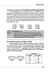
This mainboard has a System Hardware Monitor chipset on-board, so that are compliant with Intel® I/O Connectivity Design Guide. CFAN1 supports the fan control. GND +12V SENSOR CFAN1 GND +12V SENSOR SFAN1 GND +12V SENSOR PWFAN1 GND +12V SENSOR PWFAN2 MSI Reminds You... 1. Front USB Connectors: JUSB1 / JUSB2 The mainboard provides two USB...
This mainboard has a System Hardware Monitor chipset on-board, so that are compliant with Intel® I/O Connectivity Design Guide. CFAN1 supports the fan control. GND +12V SENSOR CFAN1 GND +12V SENSOR SFAN1 GND +12V SENSOR PWFAN1 GND +12V SENSOR PWFAN2 MSI Reminds You... 1. Front USB Connectors: JUSB1 / JUSB2 The mainboard provides two USB...
User Guide
Page 43
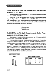
... connectors SER1& SER2. MS-6702 ATX Mainboard Serial ATA/Serial ATA RAID Connectors controlled by Promise 20378: IDE3, SER1 & SER2 The brand new Promise 20378 chipset supports one IDE slave. SATA1 & SATA2 are dual high-speed Serial ATA interface ports. You can connect up to 1 hard disk device. IDE3 is VT8237...
... connectors SER1& SER2. MS-6702 ATX Mainboard Serial ATA/Serial ATA RAID Connectors controlled by Promise 20378: IDE3, SER1 & SER2 The brand new Promise 20378 chipset supports one IDE slave. SATA1 & SATA2 are dual high-speed Serial ATA interface ports. You can connect up to 1 hard disk device. IDE3 is VT8237...
User Guide
Page 53
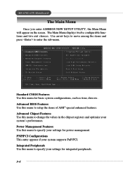
... menu to specify your settings for basic system configurations, such as time, date etc. Integrated Peripherals Use this menu to change the values in the chipset registers and optimize your system supports PnP/PCI. Standard CMOS Features Use this menu to specify your settings for power management. Power Management Features Use...
... menu to specify your settings for basic system configurations, such as time, date etc. Integrated Peripherals Use this menu to change the values in the chipset registers and optimize your system supports PnP/PCI. Standard CMOS Features Use this menu to specify your settings for power management. Power Management Features Use...
User Guide
Page 60
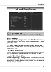
... maximum operating frequency of the HyperTransport link. Setting options: DDR200, DDR266, DDR300, DDR333, DDR400. 3-11 Change these settings only if you are familiar with the chipset. LDT to AGP Width (Downstream) These two item control the utilized widths of the link's transmitter clock. Memclock Mode / Memclock Value When it is prevented...
... maximum operating frequency of the HyperTransport link. Setting options: DDR200, DDR266, DDR300, DDR333, DDR400. 3-11 Change these settings only if you are familiar with the chipset. LDT to AGP Width (Downstream) These two item control the utilized widths of the link's transmitter clock. Memclock Mode / Memclock Value When it is prevented...
User Guide
Page 63
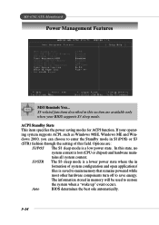
...occurs. S3/STR The S3 sleep mode is a lower power state where the in formation of this state, no system context is lost (CPU or chipset) and hardware main- S3-related functions described in S1(POS) or S3 (STR) fashion through the setting of system configuration and open applications/ files ... supports ACPI, such as Windows 98SE, Windows ME and Win- Options are available only when your operat- MS-6702 ATX Mainboard Power Management Features MSI Reminds You... The information stored in memory will be used to enter the Standby mode in this section are : S1/POS The S1 sleep mode...
...occurs. S3/STR The S3 sleep mode is a lower power state where the in formation of this state, no system context is lost (CPU or chipset) and hardware main- S3-related functions described in S1(POS) or S3 (STR) fashion through the setting of system configuration and open applications/ files ... supports ACPI, such as Windows 98SE, Windows ME and Win- Options are available only when your operat- MS-6702 ATX Mainboard Power Management Features MSI Reminds You... The information stored in memory will be used to enter the Standby mode in this section are : S1/POS The S1 sleep mode...