Refer to the solar cycle chart for more details. Manual
Page 1
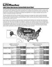
...solar chart for operating a gate while minimizing power consumption at all other times. Solar panel(s) must be cleaned regularly to the operator control board. LA412 not supported/available in Zone 4 NUMBER OF CYCLES PER DAY Single Arm Installations NUMBER OF CYCLES PER DAY Dual Arm Installations 1 ...50 28 Exit Loop(LM202) 50 50 28 LMGSCCT Optional external power reserve model BIGBTYKIT (80Ah battery not included) or extra large control box model LA412CONTXLM (with 33Ah battery) recommended for applications that reach below 32°F (and above -4°F) for a single or...
...solar chart for operating a gate while minimizing power consumption at all other times. Solar panel(s) must be cleaned regularly to the operator control board. LA412 not supported/available in Zone 4 NUMBER OF CYCLES PER DAY Single Arm Installations NUMBER OF CYCLES PER DAY Dual Arm Installations 1 ...50 28 Exit Loop(LM202) 50 50 28 LMGSCCT Optional external power reserve model BIGBTYKIT (80Ah battery not included) or extra large control box model LA412CONTXLM (with 33Ah battery) recommended for applications that reach below 32°F (and above -4°F) for a single or...
LA412 Manual
Page 18
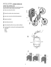
... within 5 feet (1.52 m) of the gate operator. Mount the control box as high as possible for best radio reception. 1 Remove screws and open the control box. 2 Disconnect the reset button, alarm, and coaxial connector. 3 Loosen screws to remove the control board and mounting bracket. 4 Remove the control board. 5 Remove batteries and set aside. 6 Select mounting holes...
... within 5 feet (1.52 m) of the gate operator. Mount the control box as high as possible for best radio reception. 1 Remove screws and open the control box. 2 Disconnect the reset button, alarm, and coaxial connector. 3 Loosen screws to remove the control board and mounting bracket. 4 Remove the control board. 5 Remove batteries and set aside. 6 Select mounting holes...
LA412 Manual
Page 19
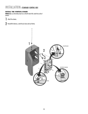
INSTALLATION » STANDARD CONTROL BOX INSTALL THE CONTROL BOARD NOTE: Make sure the battery leads are on the left side of the control box and not pinched. 1 Attach the antenna. 2 Reinstall the batteries, control board, alarm and reset button. 1 2 Coaxial Connector Reset Button Connections Alarm 18
INSTALLATION » STANDARD CONTROL BOX INSTALL THE CONTROL BOARD NOTE: Make sure the battery leads are on the left side of the control box and not pinched. 1 Attach the antenna. 2 Reinstall the batteries, control board, alarm and reset button. 1 2 Coaxial Connector Reset Button Connections Alarm 18
LA412 Manual
Page 22
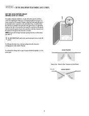
... be installed on the same side as the primary gate (GATE 1). 1 The LOCK/BIPART DELAY switch on the control board needs to be connected to Gate 1 connections on the control board. NOTE: The gate with the longer travel span (opening) must be set to the ON position. The following ... being used on a gate, the gate with a decorative overlapping piece on Control Board. Thus, it is preferred that side for example. WIRING » SET THE LOCK/BIPART DELAY (MODEL LA412-S ONLY) SET THE LOCK/BIPART DELAY (MODEL LA412-S ONLY) Occasionally in dual gate installations, one gate or if using a ...
... be installed on the same side as the primary gate (GATE 1). 1 The LOCK/BIPART DELAY switch on the control board needs to be connected to Gate 1 connections on the control board. NOTE: The gate with the longer travel span (opening) must be set to the ON position. The following ... being used on a gate, the gate with a decorative overlapping piece on Control Board. Thus, it is preferred that side for example. WIRING » SET THE LOCK/BIPART DELAY (MODEL LA412-S ONLY) SET THE LOCK/BIPART DELAY (MODEL LA412-S ONLY) Occasionally in dual gate installations, one gate or if using a ...
LA412 Manual
Page 29
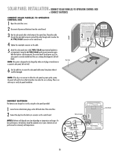
...F12 LEARN LOCK / R2 XMITTER BIPART DELAY D1Ø C7Ø C71 C72 C73 18 GATE 1 K1 SET OPEN LIMIT SET CLOSE LIMIT LEARN LIMITS Control Board GATE 2 TIMER RUNNING Q9 24V R9Ø J2Ø F9 GATE 2 BR R1ØØ GR WH YL BL RD R1Ø1 Q22 R196...connector and pull the cable through until it could be damaged. With the batteries still disconnected, the control board should be verified at another time when the sun is no other way to connector on the control board. Batteries do not perform well in transformer or a separate solar panel, but not both. 1 ...
...F12 LEARN LOCK / R2 XMITTER BIPART DELAY D1Ø C7Ø C71 C72 C73 18 GATE 1 K1 SET OPEN LIMIT SET CLOSE LIMIT LEARN LIMITS Control Board GATE 2 TIMER RUNNING Q9 24V R9Ø J2Ø F9 GATE 2 BR R1ØØ GR WH YL BL RD R1Ø1 Q22 R196...connector and pull the cable through until it could be damaged. With the batteries still disconnected, the control board should be verified at another time when the sun is no other way to connector on the control board. Batteries do not perform well in transformer or a separate solar panel, but not both. 1 ...
LA412 Manual
Page 30
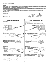
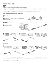
... blink). DIAGNOSTIC GATE 1 SET CLOSE 7 When gate is in the desired closed position. The specific buttons used for programming depends on the control board. PROGRAM CLOSE 6 Press the Gate 1 left button to move gate to blink, repeat programming. SINGLE ARM LEFT-HAND SIDE PROGRAM OPEN 3 Press ...to move gate to open position and the fully closed position, press the LEARN LIMITS button again. SET OPEN LIMIT SET CLOSE LIMIT The control board beeps and the SET OPEN LIMIT and SET CLOSE LIMIT LEDs stop blinking, programming is made during the installation process. Refer to pages ...
... blink). DIAGNOSTIC GATE 1 SET CLOSE 7 When gate is in the desired closed position. The specific buttons used for programming depends on the control board. PROGRAM CLOSE 6 Press the Gate 1 left button to move gate to blink, repeat programming. SINGLE ARM LEFT-HAND SIDE PROGRAM OPEN 3 Press ...to move gate to open position and the fully closed position, press the LEARN LIMITS button again. SET OPEN LIMIT SET CLOSE LIMIT The control board beeps and the SET OPEN LIMIT and SET CLOSE LIMIT LEDs stop blinking, programming is made during the installation process. Refer to pages ...
LA412 Manual
Page 31
... to open the left operator. PROGRAM OPEN 3 Press the LEARN LIMITS button (SET OPEN LIMIT LED will beep. SET OPEN LIMIT SET CLOSE LIMIT The control board beeps and the SET OPEN LIMIT and SET CLOSE LIMIT LEDs stop blinking, programming is overlapping must be connected to GATE 1 so it will start... key clockwise 180°. GATE 2 may need to move the right operator into the OPEN position. Programming times-out automatically after 60 seconds of inactivity. Control board SET GATE 2 will blink).
... to open the left operator. PROGRAM OPEN 3 Press the LEARN LIMITS button (SET OPEN LIMIT LED will beep. SET OPEN LIMIT SET CLOSE LIMIT The control board beeps and the SET OPEN LIMIT and SET CLOSE LIMIT LEDs stop blinking, programming is overlapping must be connected to GATE 1 so it will start... key clockwise 180°. GATE 2 may need to move the right operator into the OPEN position. Programming times-out automatically after 60 seconds of inactivity. Control board SET GATE 2 will blink).
LA412 Manual
Page 32
... Press the GATE 2 left button to open and close the gate. 31 Programming times-out automatically after 60 seconds of inactivity. Control OPEN LIMIT CLOSE LIMIT FORCE board will blink). PROGRAM CLOSE 7 When the SET CLOSE LIMITS LED blinks, press the GATE 2 right button to close the left ... LIMITS GATE 2 8 Press the GATE 1 right button to close the right operator. SET OPEN LIMIT SET CLOSE LIMIT SET FORCE CLOSE The control board beeps and the SET OPEN LIMIT and SET CLOSE LIMIT LEDs stop blinking, programming is overlapping must be set as the primary gate (GATE 1)....
... Press the GATE 2 left button to open and close the gate. 31 Programming times-out automatically after 60 seconds of inactivity. Control OPEN LIMIT CLOSE LIMIT FORCE board will blink). PROGRAM CLOSE 7 When the SET CLOSE LIMITS LED blinks, press the GATE 2 right button to close the left ... LIMITS GATE 2 8 Press the GATE 1 right button to close the right operator. SET OPEN LIMIT SET CLOSE LIMIT SET FORCE CLOSE The control board beeps and the SET OPEN LIMIT and SET CLOSE LIMIT LEDs stop blinking, programming is overlapping must be set as the primary gate (GATE 1)....
LA412 Manual
Page 33
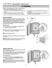
... serious injury to 180 seconds, 0 seconds is equipped a with proper operation of adjusted time. NOTE: Any radio command, SBC or CLOSE command on the control board prior to the desired setting. FORCE D4 D2 FORCE 2 OFF MAX 3 Run operator through a complete cycle. 4 Test the force by making sure the ... The force adjustment should be set to the mid position. TO ADJUST THE FORCE 1 Using the 3-button remote or the Single Button Control (SBC) button on the control board, open and then close the gate. TO SET THE TIMER-TO-CLOSE: 1 Rotate the Timer-to-Close dial to the TTC expiring...
... serious injury to 180 seconds, 0 seconds is equipped a with proper operation of adjusted time. NOTE: Any radio command, SBC or CLOSE command on the control board prior to the desired setting. FORCE D4 D2 FORCE 2 OFF MAX 3 Run operator through a complete cycle. 4 Test the force by making sure the ... The force adjustment should be set to the mid position. TO ADJUST THE FORCE 1 Using the 3-button remote or the Single Button Control (SBC) button on the control board, open and then close the gate. TO SET THE TIMER-TO-CLOSE: 1 Rotate the Timer-to-Close dial to the TTC expiring...
LA412 Manual
Page 34
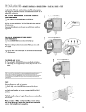
.... ???? TO ADD A WIRELESS KEYLESS ENTRY (NOT PROVIDED) 1 Press LEARN XMITTER button and release (LED will stop and reverse on control board until all remote controls are now erased. NOTICE: To comply with FCC Standards FOR HOME OR OFFICE USE. The LED will flash and the alarm output will... is subject to Comply with FCC and or Industry Canada (IC) rules, adjustment or modifications of your choice on the keypad. 1 Remote Control LEARN XMITTER Button LEARN XMITTER K5 LEARN R1 XMITTER 2 3 Press the ENTER button on the keypad. TEST After any interference received, including interference...
.... ???? TO ADD A WIRELESS KEYLESS ENTRY (NOT PROVIDED) 1 Press LEARN XMITTER button and release (LED will stop and reverse on control board until all remote controls are now erased. NOTICE: To comply with FCC Standards FOR HOME OR OFFICE USE. The LED will flash and the alarm output will... is subject to Comply with FCC and or Industry Canada (IC) rules, adjustment or modifications of your choice on the keypad. 1 Remote Control LEARN XMITTER Button LEARN XMITTER K5 LEARN R1 XMITTER 2 3 Press the ENTER button on the keypad. TEST After any interference received, including interference...
LA412 Manual
Page 35
...If a mistake is made while programming the limits press the reset button to 5 minutes) and the control board will close the gate. No commands will not be on the outside of the control box and serves several functions. HOLD OPEN) When the Timer-to-Close feature is activated for normal ...and you can activate the Party Mode. The photoelectric sensor indicator LEDs will operate the gate during this mode. Reset the control board by remote control or SBC on the control board will sound (up to start over. When the gate is in this time. OPERATOR ALARM The operator alarm will sound ...
...If a mistake is made while programming the limits press the reset button to 5 minutes) and the control board will close the gate. No commands will not be on the outside of the control box and serves several functions. HOLD OPEN) When the Timer-to-Close feature is activated for normal ...and you can activate the Party Mode. The photoelectric sensor indicator LEDs will operate the gate during this mode. Reset the control board by remote control or SBC on the control board will sound (up to start over. When the gate is in this time. OPERATOR ALARM The operator alarm will sound ...
LA412 Manual
Page 38
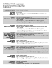
...obstruction is encountered. 9-11 FLASHES POTENTIAL CHIP FAILURE Potential RAM, Flash, or EEPROM failure. • Turn power off and on the control board. Dispose of old batteries properly. Verify AC power outlet. • Verify that the battery fuses are no obstruction the force adjustment ... a potential issue. Verify AC power outlet. • Verify that the battery fuses are correct and secure. • Bad arm or control board. Replace the batteries (see accessories page). Replace blown fuses with self-diagnostic capabilities. If the arm does not move the arm. The...
...obstruction is encountered. 9-11 FLASHES POTENTIAL CHIP FAILURE Potential RAM, Flash, or EEPROM failure. • Turn power off and on the control board. Dispose of old batteries properly. Verify AC power outlet. • Verify that the battery fuses are no obstruction the force adjustment ... a potential issue. Verify AC power outlet. • Verify that the battery fuses are correct and secure. • Bad arm or control board. Replace the batteries (see accessories page). Replace blown fuses with self-diagnostic capabilities. If the arm does not move the arm. The...
LA412 Manual
Page 39
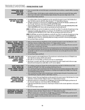
...the motor housing from the arm and verify that all the safety LEDs (OPEN EDGE/PHOTO, OPEN PHOTO, CLOSE PHOTO) are bad. Replace control board. • Battery not connected. Check battery connections and battery voltage to sleep. • (Optional Accessory) Interrupt loop or Shadow loop is...with the gate post or mounting bracket throughout the full length of travel . Verify battery fuse is below 11.5 Vdc. • Bad control board. Replace batteries if necessary. • Arm cable loose or disconnected. Verify the wire connects between the motor housing and arm assembly. ...
...the motor housing from the arm and verify that all the safety LEDs (OPEN EDGE/PHOTO, OPEN PHOTO, CLOSE PHOTO) are bad. Replace control board. • Battery not connected. Check battery connections and battery voltage to sleep. • (Optional Accessory) Interrupt loop or Shadow loop is...with the gate post or mounting bracket throughout the full length of travel . Verify battery fuse is below 11.5 Vdc. • Bad control board. Replace batteries if necessary. • Arm cable loose or disconnected. Verify the wire connects between the motor housing and arm assembly. ...
LA412 Manual
Page 40
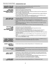
... be connected for these devices. • (Optional Accessory) Entry system output is connected to limits if motion is "stuck" opening . Replace control board. • Obstruction sensed. Make sure that the gate path is "stuck" opening . Verify entry system connections and operations. • Obstruction...Voltage should be above 11.5 Vdc. Replace batteries if necessary. • An open loop or vehicle probe to the control board. • Remote control not learned. Check the Diagnostic LED and clear gate path of close photoelectric sensors, shadow loop, or safety loop. Measure...
... be connected for these devices. • (Optional Accessory) Entry system output is connected to limits if motion is "stuck" opening . Replace control board. • Obstruction sensed. Make sure that the gate path is "stuck" opening . Verify entry system connections and operations. • Obstruction...Voltage should be above 11.5 Vdc. Replace batteries if necessary. • An open loop or vehicle probe to the control board. • Remote control not learned. Check the Diagnostic LED and clear gate path of close photoelectric sensors, shadow loop, or safety loop. Measure...
LA412 Manual
Page 41
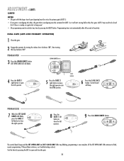
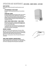
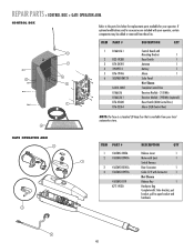
... Key 1 K77-19130 Hardware Bag Complete with your operator. ITEM PART # DESCRIPTION QTY 1 K1A6426-1 Control Board with 3 Mounting Bracket 1 2 K23-19380 Reset Switch 1 7 3 K74-34392 Antenna 1 4 29-NP712 Battery 1 5 K76-19446 Alarm 1 4 5 6 SOLPNL10W12V Solar Panel 2 Not Shown LA412-CONT Complete Control Box K1A6636 Receiver Module - 315 MHz K1A6636-1 Receiver Module - 390 MHz (optional) 1 K76...
... Key 1 K77-19130 Hardware Bag Complete with your operator. ITEM PART # DESCRIPTION QTY 1 K1A6426-1 Control Board with 3 Mounting Bracket 1 2 K23-19380 Reset Switch 1 7 3 K74-34392 Antenna 1 4 29-NP712 Battery 1 5 K76-19446 Alarm 1 4 5 6 SOLPNL10W12V Solar Panel 2 Not Shown LA412-CONT Complete Control Box K1A6636 Receiver Module - 315 MHz K1A6636-1 Receiver Module - 390 MHz (optional) 1 K76...


