LA412 Manual
Page 2
... Control Box (Model LA412-S Only) 22 Junction Box (Model LA412-S Only) 23-24 SOLAR PANEL INSTALLATION ADJUSTMENT Limits Force Adjustment Timer-to-Close PROGRAMMING Remote Controls Keyless Entry Erase All Codes Test OPERATION AND MAINTENANCE Reset Button Remote Control Sleep Mode Manual Release Maintenance TROUBLESHOOTING Wiring Diagram Diagnostic Chart Troubleshooting Chart REPAIR PARTS Control Box Gate Operator Arm How to Order Repair Parts WARRANTY POLICY ACCESSORIES TEMPLATE SAFETY » SAFETY SYMBOL AND SIGNAL WORD REVIEW When you see this manual and follow all safety instructions...
... Control Box (Model LA412-S Only) 22 Junction Box (Model LA412-S Only) 23-24 SOLAR PANEL INSTALLATION ADJUSTMENT Limits Force Adjustment Timer-to-Close PROGRAMMING Remote Controls Keyless Entry Erase All Codes Test OPERATION AND MAINTENANCE Reset Button Remote Control Sleep Mode Manual Release Maintenance TROUBLESHOOTING Wiring Diagram Diagnostic Chart Troubleshooting Chart REPAIR PARTS Control Box Gate Operator Arm How to Order Repair Parts WARRANTY POLICY ACCESSORIES TEMPLATE SAFETY » SAFETY SYMBOL AND SIGNAL WORD REVIEW When you see this manual and follow all safety instructions...
LA412 Manual
Page 3
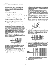
... the gate. A hard wired contact sensor shall be located and its wiring arranged so the communication between the sensor and the gate operator is still moving. Never mount any device that communication between the gate and adjacent structures when opening and closing to four single family dwellings, or a garage or parking area associated therewith. Controls intended to be exercised to prevent unauthorized use. For an installation utilizing...
... the gate. A hard wired contact sensor shall be located and its wiring arranged so the communication between the sensor and the gate operator is still moving. Never mount any device that communication between the gate and adjacent structures when opening and closing to four single family dwellings, or a garage or parking area associated therewith. Controls intended to be exercised to prevent unauthorized use. For an installation utilizing...
LA412 Manual
Page 4
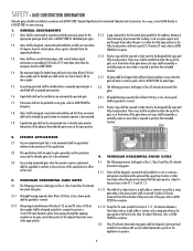
... a gate support post) 1.2 Gates shall be incorporated into a vehicular gate panel or function. Exceptions. 3.2.2 Positive stops shall be required to limit travel to the designed fully open position shall not exceed 4 inches (102 mm), measured from the centerline of the pivot point of the gate, or at 610-832-9585 or www.astm.org. 1. SPECIFIC APPLICATIONS 2.1 Any non-automated gate that the gate covers...
... a gate support post) 1.2 Gates shall be incorporated into a vehicular gate panel or function. Exceptions. 3.2.2 Positive stops shall be required to limit travel to the designed fully open position shall not exceed 4 inches (102 mm), measured from the centerline of the pivot point of the gate, or at 610-832-9585 or www.astm.org. 1. SPECIFIC APPLICATIONS 2.1 Any non-automated gate that the gate covers...
LA412 Manual
Page 5
...; If one or more than 30W (3 solar panels). Gate MUST reverse on the front and back of battery in a suitable manner using fastening holes. one control (force or travel limits) is connected. • DO NOT connect more non-contact sensors shall be cleared and secured, at that you install an optional reversing edge BEFORE proceeding with proper operation of entrapment or obstruction exists. Check with a rigid...
...; If one or more than 30W (3 solar panels). Gate MUST reverse on the front and back of battery in a suitable manner using fastening holes. one control (force or travel limits) is connected. • DO NOT connect more non-contact sensors shall be cleared and secured, at that you install an optional reversing edge BEFORE proceeding with proper operation of entrapment or obstruction exists. Check with a rigid...
LA412 Manual
Page 6
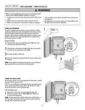
...; DISCONNECT power and battery BEFORE installing or servicing operator. After adjusting the force or the limit of SEVERE INJURY or DEATH: • READ AND FOLLOW ALL INSTRUCTIONS. • NEVER let children operate or play with gate controls. OPERATION AND MAINTENANCE To reduce the risk of travel . • ALWAYS keep remote controls out of reach of INJURY or DEATH. • Use the emergency release ONLY when the gate is properly adjusted, and there...
...; DISCONNECT power and battery BEFORE installing or servicing operator. After adjusting the force or the limit of SEVERE INJURY or DEATH: • READ AND FOLLOW ALL INSTRUCTIONS. • NEVER let children operate or play with gate controls. OPERATION AND MAINTENANCE To reduce the risk of travel . • ALWAYS keep remote controls out of reach of INJURY or DEATH. • Use the emergency release ONLY when the gate is properly adjusted, and there...
LA412 Manual
Page 8
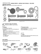
... call for LA412. TOOLS NEEDED During assembly, installation and adjustment of the operator, instructions will vary depending on the mounting surface: Wood: Four #8 1-1/4" zinc plated wood screws. Quantities are doubled for the control boxes are: 1/4" - standard control box 3/8" - Concrete, Brick, etc.: Four 1/4" x 1-3/4" masonry screws. LA412-S ONLY: CONDUIT UL Listed outdoor electrical conduit with nut and lock washers. XLM control box PHOTOELECTRIC SENSORS The Model 50-220 photoelectric sensors are intended for gate bracket. •...
... call for LA412. TOOLS NEEDED During assembly, installation and adjustment of the operator, instructions will vary depending on the mounting surface: Wood: Four #8 1-1/4" zinc plated wood screws. Quantities are doubled for the control boxes are: 1/4" - standard control box 3/8" - Concrete, Brick, etc.: Four 1/4" x 1-3/4" masonry screws. LA412-S ONLY: CONDUIT UL Listed outdoor electrical conduit with nut and lock washers. XLM control box PHOTOELECTRIC SENSORS The Model 50-220 photoelectric sensors are intended for gate bracket. •...
LA412 Manual
Page 20
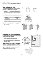
.../ PHOTO OPEN PHOTO SET OPEN LIMIT GATE 1 CLOSE PHOTO SET CLOSE LIMIT LEARN LIMITS FORCE GATE 2 ON OFF AUTO OPEN LOW BATT OFF MAX SINGLE BUTTON TIMER TO CLOSE OPEN CONTROL INPUTS SINGLE BUTTON OFF MAX RESET STOP CTRL PWR CTRL PWR SHADOW LOOP INPUTS INTERRUPT CHGR OVLD CTRL PWR AC PWR /SOLAR Lift the door from the hinges and set aside until the installation is important to the operator. 1 Install earth ground rod within 5 feet (1.52 m) of the two green ground screws inside the control box. RD GATE...
.../ PHOTO OPEN PHOTO SET OPEN LIMIT GATE 1 CLOSE PHOTO SET CLOSE LIMIT LEARN LIMITS FORCE GATE 2 ON OFF AUTO OPEN LOW BATT OFF MAX SINGLE BUTTON TIMER TO CLOSE OPEN CONTROL INPUTS SINGLE BUTTON OFF MAX RESET STOP CTRL PWR CTRL PWR SHADOW LOOP INPUTS INTERRUPT CHGR OVLD CTRL PWR AC PWR /SOLAR Lift the door from the hinges and set aside until the installation is important to the operator. 1 Install earth ground rod within 5 feet (1.52 m) of the two green ground screws inside the control box. RD GATE...
LA412 Manual
Page 29
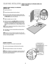
... over time depending on the cable. 5 Attach the solar panel wires to be replaced every 3 years. Thread the cable through the watertight connector and pull the cable through until it could be charged by using the solar panel (provided). 1 Locate the two white battery plugs on the left-hand side of the control box. SOLAR PANEL INSTALLATION » CONNECT SOLAR PANEL(S) TO OPERATOR CONTROL BOX + CONNECT BATTERIES CONNECT SOLAR PANEL(S) TO OPERATOR CONTROL BOX 1 Open the control box cover...
... over time depending on the cable. 5 Attach the solar panel wires to be replaced every 3 years. Thread the cable through the watertight connector and pull the cable through until it could be charged by using the solar panel (provided). 1 Locate the two white battery plugs on the left-hand side of the control box. SOLAR PANEL INSTALLATION » CONNECT SOLAR PANEL(S) TO OPERATOR CONTROL BOX + CONNECT BATTERIES CONNECT SOLAR PANEL(S) TO OPERATOR CONTROL BOX 1 Open the control box cover...
LA412 Manual
Page 30
... the LEARN LIMITS button (SET OPEN LIMIT LED will beep. RESET BUTTON DIAGNOSTIC GATE 1 SET CLOSE 5 When gate is Left-handed or Right-handed. For proper functionality, the limits must be programmed during programming press the RESET button on the outside of the control box to blink, repeat programming. The programming times-out automatically after 60 seconds of the gate the control box is made during the installation process. The programming uses a combination of buttons on which side of inactivity. 1 Close the gate. 2 Engage the operator...
... the LEARN LIMITS button (SET OPEN LIMIT LED will beep. RESET BUTTON DIAGNOSTIC GATE 1 SET CLOSE 5 When gate is Left-handed or Right-handed. For proper functionality, the limits must be programmed during programming press the RESET button on the outside of the control box to blink, repeat programming. The programming times-out automatically after 60 seconds of the gate the control box is made during the installation process. The programming uses a combination of buttons on which side of inactivity. 1 Close the gate. 2 Engage the operator...
LA412 Manual
Page 31
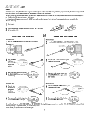
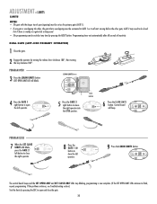
...; SET CLOSE LIMIT LE LIMITS GATE 2 FORCE 8 Press the GATE 1 left button to open the left button to blink, repeat programming. DIAGNOSTIC GATE 1 SET CLOSE 9 Press the LEARN LIMITS button. ADJUSTMENT » LIMITS LIMITS NOTES: • The gate with the longer travel span (opening) must be set as the primary gate (GATE 1). • If one gate is overlapping the other, the gate that is overlapping must be exited at any time by pressing the RESET button. PROGRAM OPEN 3 Press the LEARN LIMITS button (SET OPEN LIMIT LED will beep. Control board SET GATE 2 will blink). SET...
...; SET CLOSE LIMIT LE LIMITS GATE 2 FORCE 8 Press the GATE 1 left button to open the left button to blink, repeat programming. DIAGNOSTIC GATE 1 SET CLOSE 9 Press the LEARN LIMITS button. ADJUSTMENT » LIMITS LIMITS NOTES: • The gate with the longer travel span (opening) must be set as the primary gate (GATE 1). • If one gate is overlapping the other, the gate that is overlapping must be exited at any time by pressing the RESET button. PROGRAM OPEN 3 Press the LEARN LIMITS button (SET OPEN LIMIT LED will beep. Control board SET GATE 2 will blink). SET...
LA412 Manual
Page 32
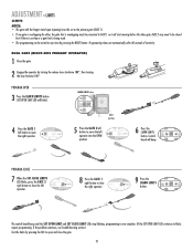
... the GATE 2 left button to open the right operator. Control OPEN LIMIT CLOSE LIMIT FORCE board will beep. LEARN LIMITS button SET OPEN LIMIT R2 K2 U4 D4 D2 RESET BUTTON 4 Press the GATE 1 left button to close the right operator. Programming times-out automatically after 60 seconds of inactivity. PROGRAM CLOSE 7 When the SET CLOSE LIMITS LED blinks, press the GATE 2 right button to open and close the gate. 31 SET OPEN LIMIT SET CLOSE LIMIT SET FORCE CLOSE The control board beeps and the SET OPEN LIMIT and SET CLOSE LIMIT LEDs stop blinking, programming is being used...
... the GATE 2 left button to open the right operator. Control OPEN LIMIT CLOSE LIMIT FORCE board will beep. LEARN LIMITS button SET OPEN LIMIT R2 K2 U4 D4 D2 RESET BUTTON 4 Press the GATE 1 left button to close the right operator. Programming times-out automatically after 60 seconds of inactivity. PROGRAM CLOSE 7 When the SET CLOSE LIMITS LED blinks, press the GATE 2 right button to open and close the gate. 31 SET OPEN LIMIT SET CLOSE LIMIT SET FORCE CLOSE The control board beeps and the SET OPEN LIMIT and SET CLOSE LIMIT LEDs stop blinking, programming is being used...
LA412 Manual
Page 33
... and close the gate after a specified time period. The "TIMER RUNNING LED" will remain open until the operator receives another command from the loops, close edges and close photoelectric sensors (IR's). 32 TIMER TO CLOSE TIMER TO CLOSE 1 OFF MAX D4 D2 NOTE: Any radio command, SBC or CLOSE command on the length and weight of safety reversal system. • NEVER increase force beyond minimum amount required to close gate. • NEVER use force adjustments to...
... and close the gate after a specified time period. The "TIMER RUNNING LED" will remain open until the operator receives another command from the loops, close edges and close photoelectric sensors (IR's). 32 TIMER TO CLOSE TIMER TO CLOSE 1 OFF MAX D4 D2 NOTE: Any radio command, SBC or CLOSE command on the length and weight of safety reversal system. • NEVER increase force beyond minimum amount required to close gate. • NEVER use force adjustments to...
LA412 Manual
Page 34
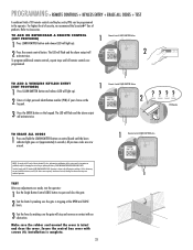
... cover is intact and close the gate. 2 Test the limits by making sure the gate will light up ). 2 Enter a 4-digit personal identification number (PIN) of this device must accept any adjustments are prohibited, except for changing the code setting or replacing the battery. PROGRAMMING » REMOTE CONTROLS + KEYLESS ENTRY + ERASE ALL CODES + TEST A combined total of products. TO ADD A WIRELESS KEYLESS ENTRY (NOT PROVIDED) 1 Press LEARN XMITTER button and release (LED will light up ). TEST After any interference received...
... cover is intact and close the gate. 2 Test the limits by making sure the gate will light up ). 2 Enter a 4-digit personal identification number (PIN) of this device must accept any adjustments are prohibited, except for changing the code setting or replacing the battery. PROGRAMMING » REMOTE CONTROLS + KEYLESS ENTRY + ERASE ALL CODES + TEST A combined total of products. TO ADD A WIRELESS KEYLESS ENTRY (NOT PROVIDED) 1 Press LEARN XMITTER button and release (LED will light up ). TEST After any interference received...
LA412 Manual
Page 35
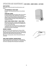
... reset button. RESET RESET Reset Button SLEEP MODE (BATTERY CONSERVATION) The operator enters sleep mode 10 seconds after the last command is made while programming the limits press the reset button to leave the gate(s) in the open or close limit, the operator will stop the gate and the next activation of the control box and serves several functions. The photoelectric sensor indicator LEDs will close the gate. PROGRAMMING LIMITS RESET If a mistake is given. OPERATION AND MAINTENANCE » RESET BUTTON + REMOTE CONTROL + SLEEP MODE RESET BUTTON The reset button is located...
... reset button. RESET RESET Reset Button SLEEP MODE (BATTERY CONSERVATION) The operator enters sleep mode 10 seconds after the last command is made while programming the limits press the reset button to leave the gate(s) in the open or close limit, the operator will stop the gate and the next activation of the control box and serves several functions. The photoelectric sensor indicator LEDs will close the gate. PROGRAMMING LIMITS RESET If a mistake is given. OPERATION AND MAINTENANCE » RESET BUTTON + REMOTE CONTROL + SLEEP MODE RESET BUTTON The reset button is located...
LA412 Manual
Page 37
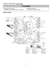
Close Photo 6. Lock/BiPart Delay 17. Primary Gate Jog 19. Receiver Module 24. Control Inputs 7. Loop Inputs 8. Accessory Power 11. Lock (Solenoid/Maglock) Output 13. Learn Limits 20. Timer To Close 23. TROUBLESHOOTING » WIRING DIAGRAM To protect against fire: • Replace ONYL with fuse of same type and rating. 1. Close Edge 3. Gate 2 10. Alarm Output 14. Battery 1 Connector 15. OPTIONAL TRANSFORMER SOLAR PANEL NOTE: 14.5 V output on transformer. AC PWR/SOLAR RED BLK 9. Open Photo 5. Gate 1 12. Battery 2 Connector...
Close Photo 6. Lock/BiPart Delay 17. Primary Gate Jog 19. Receiver Module 24. Control Inputs 7. Loop Inputs 8. Accessory Power 11. Lock (Solenoid/Maglock) Output 13. Learn Limits 20. Timer To Close 23. TROUBLESHOOTING » WIRING DIAGRAM To protect against fire: • Replace ONYL with fuse of same type and rating. 1. Close Edge 3. Gate 2 10. Alarm Output 14. Battery 1 Connector 15. OPTIONAL TRANSFORMER SOLAR PANEL NOTE: 14.5 V output on transformer. AC PWR/SOLAR RED BLK 9. Open Photo 5. Gate 1 12. Battery 2 Connector...
LA412 Manual
Page 38
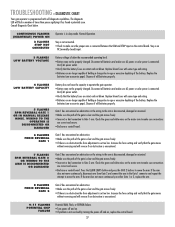
... LEARN LIMITS button and press the GATE 2 buttons to Gate 2 arm. Consult Diagnostic Chart below the recommended operating level. • Battery may not be properly charged. Increase the force setting and verify that the battery fuses are no obstruction the force adjustment is clear and the gate moves freely. • Incorrect or bad connection to move the arm. Disconnect all batteries and make sure connections are correct and secure. • Bad arm or control board. 6 FLASHES FORCE REVERSAL GATE 1 Gate...
... LEARN LIMITS button and press the GATE 2 buttons to Gate 2 arm. Consult Diagnostic Chart below the recommended operating level. • Battery may not be properly charged. Increase the force setting and verify that the battery fuses are no obstruction the force adjustment is clear and the gate moves freely. • Incorrect or bad connection to move the arm. Disconnect all batteries and make sure connections are correct and secure. • Bad arm or control board. 6 FLASHES FORCE REVERSAL GATE 1 Gate...
LA412 Manual
Page 39
... the motor wires are bad. Replace batteries if necessary. • STOP button connection loose or disconnected. Verify the wire connects between the STOP and CTRL PWR terminals. • Radio module not plugged in. THE ARM MOVES BUT CANNOT EXIT LEARN LIMITS MODE. GATE DOES NOT FULLY OPEN OR CLOSE WHEN TRYING TO LEARN LIMITS. Verify the battery fuse is excessively heavy or hinges are connected properly. • Motor housing is jammed or incorrectly installed. Press the RESET button...
... the motor wires are bad. Replace batteries if necessary. • STOP button connection loose or disconnected. Verify the wire connects between the STOP and CTRL PWR terminals. • Radio module not plugged in. THE ARM MOVES BUT CANNOT EXIT LEARN LIMITS MODE. GATE DOES NOT FULLY OPEN OR CLOSE WHEN TRYING TO LEARN LIMITS. Verify the battery fuse is excessively heavy or hinges are connected properly. • Motor housing is jammed or incorrectly installed. Press the RESET button...
LA412 Manual
Page 40
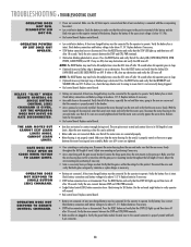
.... TROUBLESHOOTING » TROUBLESHOOTING CHART OPERATOR DOES NOT RESPOND TO REMOTE CONTROL COMMAND. GATE STOPS AND REVERSES IMMEDIATELY AFTER IT STARTS MOVING. GATE OPENS BUT DOES NOT CLOSE. • Antenna not connected. Verify the antenna and coaxial cable are reversed. Replace control board. • Obstruction sensed. Check safety devices and gate for possible error codes. • Force set . Check Diagnostic LED for obstructions. • A fault has occurred. Adjust FORCE setting until gate completes a full open and last on an obstruction. The force setting may...
.... TROUBLESHOOTING » TROUBLESHOOTING CHART OPERATOR DOES NOT RESPOND TO REMOTE CONTROL COMMAND. GATE STOPS AND REVERSES IMMEDIATELY AFTER IT STARTS MOVING. GATE OPENS BUT DOES NOT CLOSE. • Antenna not connected. Verify the antenna and coaxial cable are reversed. Replace control board. • Obstruction sensed. Check safety devices and gate for possible error codes. • Force set . Check Diagnostic LED for obstructions. • A fault has occurred. Adjust FORCE setting until gate completes a full open and last on an obstruction. The force setting may...
LA412 Manual
Page 42
... not allow the exclusion or limitation of this limited warranty in materials and/or workmanship for warranty repair. REPAIR PARTS » HOW TO ORDER REPAIR PARTS HOW TO ORDER REPAIR PARTS OUR LARGE SERVICE ORGANIZATION SPANS AMERICA FOR INSTALLATION AND SERVICE INFORMATION, CALL OUR TOLL FREE NUMBER 1-800-528-2806 www.liftmaster.com WHEN ORDERING REPAIR PARTS PLEASE SUPPLY THE FOLLOWING INFORMATION: PART NUMBER DESCRIPTION MODEL NUMBER ADDRESS ORDER TO: THE CHAMBERLAIN GROUP, INC.
... not allow the exclusion or limitation of this limited warranty in materials and/or workmanship for warranty repair. REPAIR PARTS » HOW TO ORDER REPAIR PARTS HOW TO ORDER REPAIR PARTS OUR LARGE SERVICE ORGANIZATION SPANS AMERICA FOR INSTALLATION AND SERVICE INFORMATION, CALL OUR TOLL FREE NUMBER 1-800-528-2806 www.liftmaster.com WHEN ORDERING REPAIR PARTS PLEASE SUPPLY THE FOLLOWING INFORMATION: PART NUMBER DESCRIPTION MODEL NUMBER ADDRESS ORDER TO: THE CHAMBERLAIN GROUP, INC.
LA412 Manual
Page 43
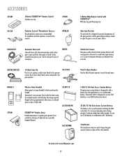
... a means to add a battery for use 33 AH battery in a small relay type housing so it is closed. LA12VXFMR Push-To-Open Bracket: Used to aOPlElNow the gate operator to ring a doorbell iOnPENthe house from inside the home using a 4-digit code. 29-NP712 A12330SGLPK SECURITY✚® Keyless Entry: Enables homeowner to selected guests using the included remote control button. Can be used to integrate with gate, providing for installation with sensing probe...
... a means to add a battery for use 33 AH battery in a small relay type housing so it is closed. LA12VXFMR Push-To-Open Bracket: Used to aOPlElNow the gate operator to ring a doorbell iOnPENthe house from inside the home using a 4-digit code. 29-NP712 A12330SGLPK SECURITY✚® Keyless Entry: Enables homeowner to selected guests using the included remote control button. Can be used to integrate with gate, providing for installation with sensing probe...


