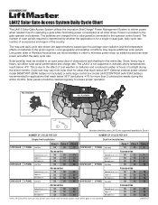
Refer to the solar cycle chart for more details. Manual
Page 1
...) 50 50 18 Loop(LD7LP) 50 50 18 Exit Loop(LM202) 50 50 18 Arms Only 50 50 30 Accessories Solenoid Lock(SGLOCK12V) 50 50 27 Loop(LD7LP) 50 50 28 Exit Loop(LM202) 50 50 28 LMGSCCT Solar panel(s) must be cleaned regularly to ... panel(s) connected to the operator control board. Snow, heavy fog or heavy rain affect solar panel performance and charge rate. LA412 Solar Gate Access System Daily Cycle Chart The LA412 Solar Gate Access System utilizes the innovative EverCharge® Power Management System to deliver power when needed most for areas that reach below...
...) 50 50 18 Loop(LD7LP) 50 50 18 Exit Loop(LM202) 50 50 18 Arms Only 50 50 30 Accessories Solenoid Lock(SGLOCK12V) 50 50 27 Loop(LD7LP) 50 50 28 Exit Loop(LM202) 50 50 28 LMGSCCT Solar panel(s) must be cleaned regularly to ... panel(s) connected to the operator control board. Snow, heavy fog or heavy rain affect solar panel performance and charge rate. LA412 Solar Gate Access System Daily Cycle Chart The LA412 Solar Gate Access System utilizes the innovative EverCharge® Power Management System to deliver power when needed most for areas that reach below...
LA412 Manual
Page 2
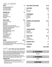
... 15 15 16 16 17-18 19 WIRING 20-24 Connect the Gate Operator (Gate 1) to the Control Box 20 Set the Lock/Bipart Delay (Model LA412-S Only) 21 Connect the Gate Operator (Gate 2) to the Control Box (Model LA412-S Only) 22 Junction Box (Model LA412-S Only) 23-24 SOLAR PANEL INSTALLATION ADJUSTMENT Limits Force Adjustment Timer-to...
... 15 15 16 16 17-18 19 WIRING 20-24 Connect the Gate Operator (Gate 1) to the Control Box 20 Set the Lock/Bipart Delay (Model LA412-S Only) 21 Connect the Gate Operator (Gate 2) to the Control Box (Model LA412-S Only) 22 Junction Box (Model LA412-S Only) 23-24 SOLAR PANEL INSTALLATION ADJUSTMENT Limits Force Adjustment Timer-to...
LA412 Manual
Page 8
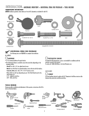
... doubled for installation with the operators covered in this manual. LA412-S ONLY: CONDUIT UL Listed outdoor electrical conduit with nut and lock washers. Concrete, Brick, etc.: Four 1/4" x 1-3/4" masonry...complete the installation: ALL MODELS: HARDWARE • 5/16" mounting hardware for LA412. To order call for tools as illustrated below are for gate bracket. • The following items are : 1/4" - standard control box ... will call 1-800-528-2806 or visit www.liftmaster.com. INTRODUCTION » HARDWARE INVENTORY + ADDITIONAL ITEMS FOR PURCHASE + TOOLS NEEDED HARDWARE ...
... doubled for installation with the operators covered in this manual. LA412-S ONLY: CONDUIT UL Listed outdoor electrical conduit with nut and lock washers. Concrete, Brick, etc.: Four 1/4" x 1-3/4" masonry...complete the installation: ALL MODELS: HARDWARE • 5/16" mounting hardware for LA412. To order call for tools as illustrated below are for gate bracket. • The following items are : 1/4" - standard control box ... will call 1-800-528-2806 or visit www.liftmaster.com. INTRODUCTION » HARDWARE INVENTORY + ADDITIONAL ITEMS FOR PURCHASE + TOOLS NEEDED HARDWARE ...
LA412 Manual
Page 12
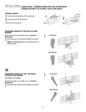
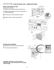
... in manual mode. SEE ACCESSORIES) The Push-To-Open bracket can be assembled to work on a Left-Hand or a Right-Hand gate. 1 Review the gate types and select the type of installation you will require. INSTALLATION » MANUAL RELEASE + DETERMINE POSITION OF THE PULL-TO-OPEN BRACKET... + DETERMINE POSITION OF THE "OPTIONAL" PUSH-TO-OPEN BRACKET MANUAL RELEASE 1 Insert the key into the lock and turn it 180° counterclockwise. ...
... in manual mode. SEE ACCESSORIES) The Push-To-Open bracket can be assembled to work on a Left-Hand or a Right-Hand gate. 1 Review the gate types and select the type of installation you will require. INSTALLATION » MANUAL RELEASE + DETERMINE POSITION OF THE PULL-TO-OPEN BRACKET... + DETERMINE POSITION OF THE "OPTIONAL" PUSH-TO-OPEN BRACKET MANUAL RELEASE 1 Insert the key into the lock and turn it 180° counterclockwise. ...
LA412 Manual
Page 13
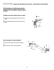
.... For push-to-open installations refer to instructions with washer, lock washer and nut. 1 2 HHexexBoBlto3lt/83"/8" Extension PBurlla-tcok-Oepten Bracket PPoostsBtrBacrkaectket WWaashsehrer LLoockckWaWshaesr her NNuut t ATTACH BRACKETS TO GATE OPERATOR 1 Attach post bracket assembly to operator using pins and hairpin...pins and hairpin clips. 1 Pin Post Bracket Assembly Hairpin Clip Pin 2 Gate Bracket Hairpin Clip 12 INSTALLATION » ASSEMBLE GATE POST BRACKET (PULL-TO-OPEN) + ATTACH BRACKETS TO GATE OPERATOR All the illustrations on top of post bracket. 2 Insert the bolt...
.... For push-to-open installations refer to instructions with washer, lock washer and nut. 1 2 HHexexBoBlto3lt/83"/8" Extension PBurlla-tcok-Oepten Bracket PPoostsBtrBacrkaectket WWaashsehrer LLoockckWaWshaesr her NNuut t ATTACH BRACKETS TO GATE OPERATOR 1 Attach post bracket assembly to operator using pins and hairpin...pins and hairpin clips. 1 Pin Post Bracket Assembly Hairpin Clip Pin 2 Gate Bracket Hairpin Clip 12 INSTALLATION » ASSEMBLE GATE POST BRACKET (PULL-TO-OPEN) + ATTACH BRACKETS TO GATE OPERATOR All the illustrations on top of post bracket. 2 Insert the bolt...
LA412 Manual
Page 15
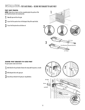
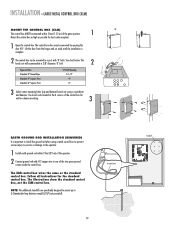
...: The post bracket assembly can be level. 2 3 Mark mounting holes on the gate post. Temporarily secure gate post bracket with washer, lock washer and nut. 1 3 4 7" (18 cm) 7" (18 cm) Hex Bolt 3/8" 5 Washer Lock Washer Nut 14 Temporarily secure the gate bracket using a clamp. 4 Align the pull-to-open bracket to a position as CLOSE AS POSSIBLE...
...: The post bracket assembly can be level. 2 3 Mark mounting holes on the gate post. Temporarily secure gate post bracket with washer, lock washer and nut. 1 3 4 7" (18 cm) 7" (18 cm) Hex Bolt 3/8" 5 Washer Lock Washer Nut 14 Temporarily secure the gate bracket using a clamp. 4 Align the pull-to-open bracket to a position as CLOSE AS POSSIBLE...
LA412 Manual
Page 16
.... 1 Mark holes for the post bracket. Flat Washers 3 Hex Nuts Lock Washers 15 2 Carriage Bolts Welder (Optional) INSTALLATION » TEST GATE TRAVEL + SECURE POST BRACKET TO GATE POST TEST GATE TRAVEL NOTE: If gate does not open and close completely adjust the position of the 1 gate bracket and mark new mounting holes. 1 Manually open and close...
.... 1 Mark holes for the post bracket. Flat Washers 3 Hex Nuts Lock Washers 15 2 Carriage Bolts Welder (Optional) INSTALLATION » TEST GATE TRAVEL + SECURE POST BRACKET TO GATE POST TEST GATE TRAVEL NOTE: If gate does not open and close completely adjust the position of the 1 gate bracket and mark new mounting holes. 1 Manually open and close...
LA412 Manual
Page 17
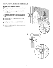
...page. 16 Inside Property Moving Gate Can Cause Injury or Death KEEP CLEAR! Some installations may move the gate to verify that it opens and closes fully. 1 Operator Angle Iron OR Wood OR Flat Bar Welder (Optional) Hex Nut Lock Washer Flat Washer 2 Gate Bracket Hex Bolt 3 WARNING SIGN... PLACEMENT Warning signs MUST be installed on the gate. 1 Drill holes in the...
...page. 16 Inside Property Moving Gate Can Cause Injury or Death KEEP CLEAR! Some installations may move the gate to verify that it opens and closes fully. 1 Operator Angle Iron OR Wood OR Flat Bar Welder (Optional) Hex Nut Lock Washer Flat Washer 2 Gate Bracket Hex Bolt 3 WARNING SIGN... PLACEMENT Warning signs MUST be installed on the gate. 1 Drill holes in the...
LA412 Manual
Page 20
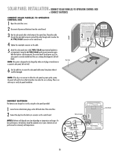
... BL RD ACCESSORY POWER 12 V BR GR WH YL BL RD GATE 2 LEARN XMITTER ON OFF LOCK / BIPA RT DELAY SET OPEN LIMIT GATE 1 SET CLOSE LIMIT LEARN LIMITS GATE 2 FORCE ON OFF AUTO OPEN LOW BATT OFF MAX ALARM LOCK SOL GND MAGR GATE 1 BR GR WH YL BL RD ACCESSORY POWER 12 V BR GR...° Mount the control box as high as the standard control box. ALARM CLOSE EDGE SOL GND OPEN EDGE/ PHOTO MAGR LOCK ON OFF LEARN XMITTER LOCK / BIPA RT DELAY OPEN PHOTO GATE 1 NOTE: BR GR WH YL BL RD TheGATE1 additional CLOSE PHOTO standoffs are specifically designed to mount up to the...
... BL RD ACCESSORY POWER 12 V BR GR WH YL BL RD GATE 2 LEARN XMITTER ON OFF LOCK / BIPA RT DELAY SET OPEN LIMIT GATE 1 SET CLOSE LIMIT LEARN LIMITS GATE 2 FORCE ON OFF AUTO OPEN LOW BATT OFF MAX ALARM LOCK SOL GND MAGR GATE 1 BR GR WH YL BL RD ACCESSORY POWER 12 V BR GR...° Mount the control box as high as the standard control box. ALARM CLOSE EDGE SOL GND OPEN EDGE/ PHOTO MAGR LOCK ON OFF LEARN XMITTER LOCK / BIPA RT DELAY OPEN PHOTO GATE 1 NOTE: BR GR WH YL BL RD TheGATE1 additional CLOSE PHOTO standoffs are specifically designed to mount up to the...
LA412 Manual
Page 22
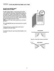
... an ornamental overhang on one gate will need to it is the primary gate. 1 ON OFF LOCK/ BIPART DELAY C7Ø C71 OUTSIDE PROPERTY Primary Gate - WIRING » SET THE LOCK/BIPART DELAY (MODEL LA412-S ONLY) SET THE LOCK/BIPART DELAY (MODEL LA412-S ONLY) Occasionally in dual gate installations, one gate or if using a solenoid lock, for the control box, then...
... an ornamental overhang on one gate will need to it is the primary gate. 1 ON OFF LOCK/ BIPART DELAY C7Ø C71 OUTSIDE PROPERTY Primary Gate - WIRING » SET THE LOCK/BIPART DELAY (MODEL LA412-S ONLY) SET THE LOCK/BIPART DELAY (MODEL LA412-S ONLY) Occasionally in dual gate installations, one gate or if using a solenoid lock, for the control box, then...
LA412 Manual
Page 26
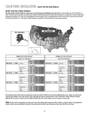
...snow. 25 NOTE: The solar panel(s) recommendation is based upon the average solar radiation and the temperature effects on gate construction and installation. The LA412 Solar Gate Operator is due to increase the number of cycles per day. Cycle rate may require additional solar panels. Local... SOLAR 20W SOLAR 30W SOLAR NUMBER OF CYCLES PER DAY Single Arm Installations 1 PANEL Arm Only 2 PANEL Solenoid Lock Loop LM202 Arm Only 3 PANEL Solenoid Lock Loop LM202 Arm Only Solenoid Lock Loop LM202 Zone 1 Zone 2 50 40 Accessories 50 35 50 31 50 31 50 50 Accessories 50 50...
...snow. 25 NOTE: The solar panel(s) recommendation is based upon the average solar radiation and the temperature effects on gate construction and installation. The LA412 Solar Gate Operator is due to increase the number of cycles per day. Cycle rate may require additional solar panels. Local... SOLAR 20W SOLAR 30W SOLAR NUMBER OF CYCLES PER DAY Single Arm Installations 1 PANEL Arm Only 2 PANEL Solenoid Lock Loop LM202 Arm Only 3 PANEL Solenoid Lock Loop LM202 Arm Only Solenoid Lock Loop LM202 Zone 1 Zone 2 50 40 Accessories 50 35 50 31 50 31 50 50 Accessories 50 50...
LA412 Manual
Page 29
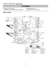
... an AC plug-in extremely cold temperatures. Leave the AC PWR/SOLAR earth ground connection open. Battery Connectors 2 Battery Connection C1Ø1 R182 1 3ØA 32V LOCK D36 SOL GND MAGR D42 Z1 GATE 1 R1 BR GR WH YL BL RD F8 Z12 L1 U4 ON OFF C75 F12 LEARN... LOCK / R2 XMITTER BIPART DELAY D1Ø C7Ø C71 C72 C73 18 GATE 1 K1 SET OPEN LIMIT SET CLOSE LIMIT LEARN LIMITS Control Board GATE 2 TIMER RUNNING Q9 24V R9Ø J2Ø F9 GATE 2 BR R1ØØ GR WH YL BL RD...
... an AC plug-in extremely cold temperatures. Leave the AC PWR/SOLAR earth ground connection open. Battery Connectors 2 Battery Connection C1Ø1 R182 1 3ØA 32V LOCK D36 SOL GND MAGR D42 Z1 GATE 1 R1 BR GR WH YL BL RD F8 Z12 L1 U4 ON OFF C75 F12 LEARN... LOCK / R2 XMITTER BIPART DELAY D1Ø C7Ø C71 C72 C73 18 GATE 1 K1 SET OPEN LIMIT SET CLOSE LIMIT LEARN LIMITS Control Board GATE 2 TIMER RUNNING Q9 24V R9Ø J2Ø F9 GATE 2 BR R1ØØ GR WH YL BL RD...
LA412 Manual
Page 31
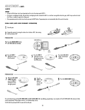
...SET CLOSE LIMIT FORCE PROGRAM CLOSE 7 When the SET CLOSE LIMITS LED blinks, press the GATE 2 left button to open and close the left button to be closed first if there is overlap or a gate lock is being used. • The programming can be connected to move the right operator into... the OPEN position. DIAGNOSTIC GATE 1 SET CLOSE 9 Press the LEARN LIMITS button. Programming times-out automatically after 60 ...
...SET CLOSE LIMIT FORCE PROGRAM CLOSE 7 When the SET CLOSE LIMITS LED blinks, press the GATE 2 left button to open and close the left button to be closed first if there is overlap or a gate lock is being used. • The programming can be connected to move the right operator into... the OPEN position. DIAGNOSTIC GATE 1 SET CLOSE 9 Press the LEARN LIMITS button. Programming times-out automatically after 60 ...
LA412 Manual
Page 32
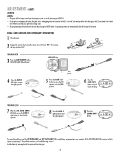
... left button to blink, repeat programming. Control OPEN LIMIT CLOSE LIMIT FORCE board will blink). DIAGNOSTIC GATE 1 9 Press the LEARN LIMITS button. GATE 2 may need to be closed first if there is overlap or a gate lock is now complete. (If the SET OPEN LIMIT LED continues to open and close the... gate. 31 PROGRAM CLOSE 7 When the SET CLOSE LIMITS LED blinks, press the GATE 2 right button to open the right operator. PROGRAM OPEN 3 ...
... left button to blink, repeat programming. Control OPEN LIMIT CLOSE LIMIT FORCE board will blink). DIAGNOSTIC GATE 1 9 Press the LEARN LIMITS button. GATE 2 may need to be closed first if there is overlap or a gate lock is now complete. (If the SET OPEN LIMIT LED continues to open and close the... gate. 31 PROGRAM CLOSE 7 When the SET CLOSE LIMITS LED blinks, press the GATE 2 right button to open the right operator. PROGRAM OPEN 3 ...
LA412 Manual
Page 36
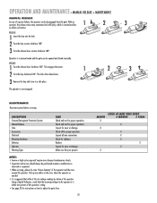
...key clockwise 180°. ENGAGE 1 Turn the release lever clockwise 180°. Using a Digital Voltmeter, verify that while at the operator. This locks the release lever. 3 Remove the key and store in the area. The operator is observed or suspected. • When servicing, please ...do some "house cleaning" of the operator and the area around the operator. DESCRIPTION External Entrapment Protection System Manual Release Gate Accessories Electrical Mounting Hardware Batteries Operator Warning Signs TASK Check and test for proper operation Check and test for proper operation ...
...key clockwise 180°. ENGAGE 1 Turn the release lever clockwise 180°. Using a Digital Voltmeter, verify that while at the operator. This locks the release lever. 3 Remove the key and store in the area. The operator is observed or suspected. • When servicing, please ...do some "house cleaning" of the operator and the area around the operator. DESCRIPTION External Entrapment Protection System Manual Release Gate Accessories Electrical Mounting Hardware Batteries Operator Warning Signs TASK Check and test for proper operation Check and test for proper operation ...
LA412 Manual
Page 37
...; Replace ONLY with fuse of same type and rating. 23 1 Fault Alarm Automatic Gate Lock (optional) * 13 BLK RED RED BLK * 12 11 BRN GRN WHT YEL BLU RED Gate 1 (Primary) 10* 12V, 500mA 9 BRN GRN WHT YEL BLU RED Gate 2 (Secondary) 24 ALARM C1Ø1 R182 J19 C66 C65 CLOSE EDGE C68 D36... SOL ACCESSORY 0VLD GND MAGR U4 K5 LOCK D42 F12 ON OFF C75 Z1 R2 LEARN XMITTER LOCK / BIPART DELAY GATE 1 R1 BR GR D1Ø C7Ø C71 16 K2 17 C72 C73 Q12 Q6 C33 Z22 OPEN EDGE/ PHOTO...
...; Replace ONLY with fuse of same type and rating. 23 1 Fault Alarm Automatic Gate Lock (optional) * 13 BLK RED RED BLK * 12 11 BRN GRN WHT YEL BLU RED Gate 1 (Primary) 10* 12V, 500mA 9 BRN GRN WHT YEL BLU RED Gate 2 (Secondary) 24 ALARM C1Ø1 R182 J19 C66 C65 CLOSE EDGE C68 D36... SOL ACCESSORY 0VLD GND MAGR U4 K5 LOCK D42 F12 ON OFF C75 Z1 R2 LEARN XMITTER LOCK / BIPART DELAY GATE 1 R1 BR GR D1Ø C7Ø C71 16 K2 17 C72 C73 Q12 Q6 C33 Z22 OPEN EDGE/ PHOTO...
LA412 Manual
Page 40
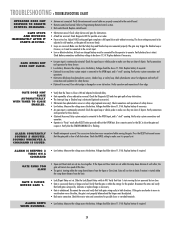
...for these devices. • (Optional Accessory) Entry system output is connected to operate. Press the RESET button and ensure that Gate 1 starts moving the gate. Measure the voltage across the battery. Voltage should be above 11.5 Vdc. Measure the voltage across the battery. Verify entry ... reversed. Verify the antenna and coaxial cable are harder to -Close is within the ramp-down distance from the limit. • Lock/Bipart Delay not set too close photoelectric sensors, shadow loop, or safety loop. Refer to make sure they are set within the...
...for these devices. • (Optional Accessory) Entry system output is connected to operate. Press the RESET button and ensure that Gate 1 starts moving the gate. Measure the voltage across the battery. Voltage should be above 11.5 Vdc. Measure the voltage across the battery. Verify entry ... reversed. Verify the antenna and coaxial cable are harder to -Close is within the ramp-down distance from the limit. • Lock/Bipart Delay not set too close photoelectric sensors, shadow loop, or safety loop. Refer to make sure they are set within the...
LA412 Manual
Page 43
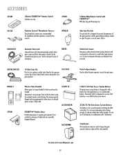
...designed to open . Keypad can be used to integrate with gate, providing for use with the operators covered in this manual. To order visit www.liftmaster.com 42 OPEN CLOSE Gate Arm Pin Lock: The pin lock kit is easy to charge the gate operator battery in case of power failure. No wiring required....keypad. SOLPNL10W12V WGB315 PRESS TO R ING 377LM 10 Watt Solar Kit: This kit is designed to the operator system. Up to the gate operator. The model LA412 is to replace or add a Solar Panel to use 33 AH battery in case of reduced sunlight and colder weather. Can be ...
...designed to open . Keypad can be used to integrate with gate, providing for use with the operators covered in this manual. To order visit www.liftmaster.com 42 OPEN CLOSE Gate Arm Pin Lock: The pin lock kit is easy to charge the gate operator battery in case of power failure. No wiring required....keypad. SOLPNL10W12V WGB315 PRESS TO R ING 377LM 10 Watt Solar Kit: This kit is designed to the operator system. Up to the gate operator. The model LA412 is to replace or add a Solar Panel to use 33 AH battery in case of reduced sunlight and colder weather. Can be ...


