
LiftMaster LA400 Support Question
LiftMaster LA400 Support Question
Find answers below for this question about LiftMaster LA400.Need a LiftMaster LA400 manual? We have 3 online manuals for this item!
Question posted by saritav on November 19th, 2011
La 400 24v Dual Gate Swing Control Board K001a6039
Is there a version of this control board that has two "learn xmitter" buttons to allow only one gate leaf to be opened instead of the normal two?
Current Answers
Related LiftMaster LA400 Manual Pages
LA400 Manual - Page 2

...Secure Post Bracket to Gate Post Secure Gate Bracket to Gate Warning Sign Placement Standard Control Box Large Metal Control Box (XLM)
WIRING
Connect the Gate Operator (Gate 1) to the Control Box Set the Bipart Delay (Model LA400-S Only) Connect the Gate Operator (Gate 2) to the Control Box (Model LA400-S Only) Junction Box (Model LA400-S Only) Connect Transformer to Control Board Earth Ground Rod...
LA400 Manual - Page 11
... while the gate is still moving.
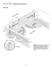
10 INSTALLATION » OVERVIEW OF TYPICAL INSTALLATION
DUAL GATE
Warning Sign Hinge
Antenna
Post Bracket
Gate Bracket
Gate 1
Control Box with Batteries
Operator Cable
Gate 2
Junction Box Extension Cable Photoelectric Sensors
PVC Conduit (not provided) to reduce the risk of entrapment or obstruction exists at either the opening or closing direction...
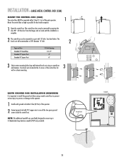
LA400 Manual - Page 19

... 5 feet (1.5 m) of the gate operator. Column
5 2 Alarm
6
2 Coaxial Connector 4
3 2 Reset Button Connections
Knock Outs
Knock Outs
Knock Outs
7
A. A. Mount the control box as high as possible for best radio reception.
1 Remove screws and open the control box.
1
2 Disconnect the reset button, alarm, and coaxial connector.
3 Loosen screws to remove the control board and mounting bracket...
LA400 Manual - Page 21
... OPEN LIMIT
GATE 2
BR
GR
GATE 1
WH
YL
SET CLOSE LIMIT
LEARN LIMITS
BL
RD
GATE 2
FORCE
ON OFF
AUTO OPEN LOW BATT
OFF MAX
LEARN XMITTER
ON
OFF
LOCK /
BIPA RT DELAY
CLOSE EDGE
SET OPEN LIMIT
OPEN EDGE/ PHOTO
GATE 1
SET CLOSE LIMIT
LEARN LIMITS
OPEN PHOTO
GATE 2
FORCE
ON OFF
CLOSE PHOTO AUTO OPEN LOW BATT
OFF MAX
SINGLE BUTTON
TIMER TO CLOSE
OPEN
CONTROL...
LA400 Manual - Page 22

... POWER
12 V
BR GR WH YL BL RD GATE 2
LEARN XMITTER
ON
OFF
LOCK /
BIPA RT DELAY
CLOSE EDGE
OPEN EDGE/ PHOTO
OPEN PHOTO
SET OPEN LIMIT
GATE 1
CLOSE PHOTO
SET CLOSE LIMIT
LEARN LIMITS
FORCE
GATE 2
ON OFF
AUTO OPEN LOW BATT
OFF MAX
SINGLE BUTTON
TIMER TO CLOSE
OPEN
CONTROL INPUTS
SINGLE BUTTON
RESET
OFF MAX
STOP CTRL PWR CTRL PWR
SHADOW...
LA400 Manual - Page 24

... gate will need to Gate 1 connections on Control Board.
The following illustration shows a dual gate configuration with the longer travel span (opening) must be
connected to open first and close second. Primary Gate
OUTSIDE PROPERTY
23
WIRING » SET THE BIPART DELAY (MODEL LA400-S ONLY)
SET THE BIPART DELAY (MODEL LA400-S ONLY)
In some dual gate installations, one gate...
LA400 Manual - Page 29
... 1 BATT 1 Connector
BATT 2 Connector
28 The operator is a battery run system. Both batteries are the main source of the control board marked . ALARM MAGLOCK
Z1 GATE 1
ACCESSORY POWER
GATE 2 R4
J4
FUSE FUOSPEEN OPEN
D15 C2
MOV2
Control Box
R4 C2 J4
24 VAC/ SOLAR INPUT
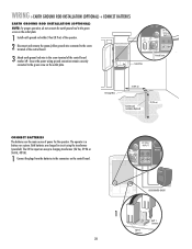
Ground Screw
12 Gauge Wire
3' (0.9 m)
Earth Ground Installation (Optional)
8' (2.4 m)
CONNECT...
LA400 Manual - Page 30

... NC PHOTO
S1
O1 2 3 4 5 N
OFF OFF SINGLE NO NO
ON SAVE ON MAGLOCK DUAL MODE NC EDGE NC PHOTO
S1
ON ON DUAL MODE NC NC
ON ON DUAL MODE NC NC
ON SAVE ON DUAL MODE NC NC
GATE 1 GATE 1 AND GATE 2
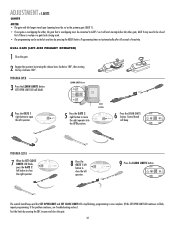
29 ADJUSTMENT » SET DIP SWITCH
SET DIP SWITCH
The Save switch must be...
LA400 Manual - Page 31
...
the LEARN LIMITS button again. Refer to pages 11 and 12 to determine if the gate is now complete. (If the SET OPEN LIMIT LED continues to open position and the fully closed position.
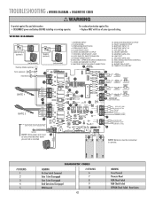
DIAGNOSTIC
GATE 1
SET CLOSE
PROGRAM CLOSE
6 When the SET CLOSE LIMIT LED blinks, press the Gate 1 right button. SET OPEN LIMIT
SET CLOSE LIMIT
The control board...
LA400 Manual - Page 32
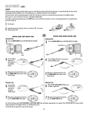
... programming. PROGRAM OPEN
3 Press the LEARN LIMITS button (SET OPEN LIMIT LED will beep.
LEARN LIMITS button
SET OPEN LIMIT
R2 K2 U4
D4 D2
RESET BUTTON
4 Press the GATE 1 right button to open the left operator.
DUAL GATE (LEFT-SIDE PRIMARY OPERATOR)
1 Close the gate.
2 Engage the operator by pressing the SBC to open and close the gate.
31 Control board
SET
SET
GATE 2
will...
LA400 Manual - Page 33

... start moving before the other , the gate that is overlapping must be set as the primary gate (GATE 1). • If one gate is overlapping the other gate; PROGRAM OPEN
3 Press the LEARN LIMITS button (SET OPEN LIMIT LED will beep.
OPEN LIMIT
SET CLOSE LIMIT
FORCE
SET CLOSE
The control board beeps and the SET OPEN LIMIT and SET CLOSE LIMIT LEDs stop...
LA400 Manual - Page 34

... automatically reverse direction and stop and reverse on the control board, open until the operator receives another command from the loops, close edges and close the gate. The force control is OFF. TO ADJUST THE FORCE
1 Using the 3-button remote or the Single Button Control (SBC) button on contact with a rigid object. If the TTC is factory set to...
LA400 Manual - Page 35
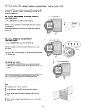
... ENTER button on control board until all remote controls are now erased. TO ADD A WIRELESS KEYLESS ENTRY (NOT PROVIDED)
1 Press LEARN XMITTER button and release (LED will light up ). Refer to Comply with FCC and or Industry Canada (IC) rules, adjustment or modifications of 50 remote controls and keyless entry PIN can be programmed to open and close the gate...
LA400 Manual - Page 37
.../OR
COMMON RESET
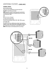
36 SBC (SINGLE BUTTON CONTROL) INPUT
C2
This input will command the gate to reset the alarms. This input will be Normally Open (N.O.) dry contact type.
NOTE: All Control Inputs must be lit except when the control board goes into Sleep Mode). ADDITIONAL FEATURES » CONTROL INPUTS
CONTROL INPUTS
WIRE STOP BUTTON (OPTIONAL)
A jumper wire is added. Stop...
LA400 Manual - Page 40
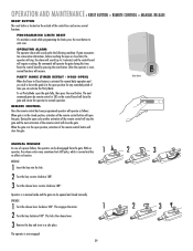
... the control board by remote control or SBC on the control board will close the gate. The next command given by pressing the reset button. When the gate is in the open position, activation of the remote control button will open the gate. Operator is in manual mode and the gate can be opened and closed position, activation of the remote control button will close the gate and...
LA400 Manual - Page 42

...
SET CLOSE LIMIT
LEARN LIMITS
R2Ø7
Z2Ø R227
J18
R224
U4
Z22
R92
R91 R94
R93
CLOSE EDGE
OPEN EDGE/ PHOTO
Z9 OPEN PHOTO
Z8 CLOSE PHOTO
24V
ACCESSORY
R9Ø
POWER
24V
R1Ø1
FORCE
GATE 2 TIMER RUNNING
BIPART DELAY
TIMER TO SINGLE CLOSE BUTTON
COM OVLD OVLD
OPEN
SWITCHED ACCESSORY
POWER
CONTROL INPUTS
GATE 2
BRN GRN...
LA400 Manual - Page 43
...
DUAL MODE
R1 XMITTER
NO
NC EDGE
NO
NC PHOTO
2
S1
F3
K2
18
19 DIAGNOSTIC
K1
Q9
SET OPEN
LIMIT
20 GATE 1
SET CLOSE LIMIT
LEARN LIMITS
R2ÿ 7
Z2ÿ R227
J18
R224
Z22 R92 U4
R91 R94
R93
CLOSE EDGE
OPEN EDGE/ PHOTO
Z9 OPEN PHOTO
Z8 CLOSE PHOTO
24V
ACCESSORY
R9ÿ
POWER
24V
GATE 2
BRN...
LA400 Manual - Page 44

...connected. Service/replace gate hardware. Operator will resume normal operation once battery voltage reaches 24 V. Check for instructions.
Use remote control/SBC to run, then stops and does not reverse. Clear all Open/Safety devices from obstruction. Replace control board. Move accessories to Single Button Input. GATE'S DO NOT OPEN/ CLOSE IN SYNC
GATE DOES NOT AUTOMATICALLY CLOSE...
LA400 Manual - Page 45

... PART #
1 K001A6039 2 K75-15480
3 K75-30764 4 K23-19380 5 K74-19499 6 K74-30762 7 K74-30763 8 K76-19446
K74-30941
K001A5747-2 K001A5747 K76-35600 K76-35364
DESCRIPTION
QTY
Control Board
1
Control Box & Cover
with Gasket
1
Control Board Bracket
1
Reset Switch... with your operator. REPAIR PARTS » CONTROL BOX + GATE OPERATOR ARM
CONTROL BOX
Refer to -Open bracket and hardware
44 44
LA400 Push to Open Addendum Manual - Page 2
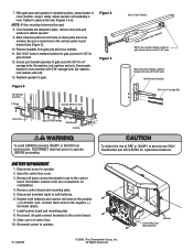
..." holes
Mark fence post through middle of post bracket slots (Figure 5).
10. Remove control board and mounting plate. 5. Reconnect all quick connect terminals to cross member, using C clamp. With gate open and operator in use ONLY Chamberlain part #K74-30762 for gate bracket.
12. Secure post bracket assembly to cross member with 3/8"-16 x 6" carriage bolts...
Similar Questions

Remote Control For Liftmaster /chamberlain 3850 Garage Door Opener
what is the correct remote control for the chamberlain/liftmaster 3850 garage door opener
what is the correct remote control for the chamberlain/liftmaster 3850 garage door opener
(Posted by sendtoalice 9 years ago)

How To Change Battery In Wall Control Garage Door Opener Model 3850 Liftmaster
(Posted by cjmanpiop 9 years ago)

Liftmaster La 400 Making 3 Beeps And Not Responding To Remote To Open Gate
(Posted by Ebgartrell 11 years ago)

Need To Register La 400 Liftmaster Gate Opener - Pls Advise Website.........
(Posted by celiagarza43 12 years ago)

Bracket To Make The La 400 Open More Than 100 Degrees
Is there A brack out the to make the LA 400 open more than 100 degrees When the gate is not at a 90 ...
Is there A brack out the to make the LA 400 open more than 100 degrees When the gate is not at a 90 ...
(Posted by nackroach 12 years ago)