

LA400 Manual
Page 2
... Switch Limits Force Adjustment Timer-to-Close PROGRAMMING Remote Controls Keyless Entry Erase All Codes Test ADDITIONAL FEATURES DIP Switch Settings Control Inputs Loop Inputs Photo/Edge Inputs (P6-7-8 and 9) Safety Accessories for Secondary Entrapment Protection OPERATION AND MAINTENANCE Reset Button Remote Control Manual Release Maintenance TROUBLESHOOTING Basic Control Board Layout Wiring Diagram Diagnostic Codes Troubleshooting Chart REPAIR PARTS Control Box Gate Operator Arm How to Order Repair Parts WARRANTY POLICY ACCESSORIES TEMPLATE SAFETY » SAFETY SYMBOL AND SIGNAL WORD REVIEW...
... Switch Limits Force Adjustment Timer-to-Close PROGRAMMING Remote Controls Keyless Entry Erase All Codes Test ADDITIONAL FEATURES DIP Switch Settings Control Inputs Loop Inputs Photo/Edge Inputs (P6-7-8 and 9) Safety Accessories for Secondary Entrapment Protection OPERATION AND MAINTENANCE Reset Button Remote Control Manual Release Maintenance TROUBLESHOOTING Basic Control Board Layout Wiring Diagram Diagnostic Codes Troubleshooting Chart REPAIR PARTS Control Box Gate Operator Arm How to Order Repair Parts WARRANTY POLICY ACCESSORIES TEMPLATE SAFETY » SAFETY SYMBOL AND SIGNAL WORD REVIEW...

LA400 Manual
Page 3
... the reverse of contact with a solid object. In order to protect people from motorized gate systems. UL325 requires that is installed on both the open and close directions of entrapment protection and one to service the general public. That means that all installations must have one primary means of gate travel. COMMERCIAL/GENERAL ACCESS VEHICULAR GATE OPERATOR II A vehicular gate operator (or system) intended for use in...
... the reverse of contact with a solid object. In order to protect people from motorized gate systems. UL325 requires that is installed on both the open and close directions of entrapment protection and one to service the general public. That means that all installations must have one primary means of gate travel. COMMERCIAL/GENERAL ACCESS VEHICULAR GATE OPERATOR II A vehicular gate operator (or system) intended for use in...

LA400 Manual
Page 4
... or easily accessible controls shall have a security feature to start. 10. One or more contact sensors shall be located and its wiring arranged so the communication between the gate and adjacent structures when opening . Pedestrians must be located on gates used for the user as well as an edge sensor: a. Locate the gate such that enough clearance is supplied between the sensor and the gate operator is specifically designed...
... or easily accessible controls shall have a security feature to start. 10. One or more contact sensors shall be located and its wiring arranged so the communication between the gate and adjacent structures when opening . Pedestrians must be located on gates used for the user as well as an edge sensor: a. Locate the gate such that enough clearance is supplied between the sensor and the gate operator is specifically designed...

LA400 Manual
Page 6
one control (force or travel limits) is adjusted, the other underground utility lines, contact underground utility locating companies BEFORE digging. To reduce the risk of FIRE or INJURY to persons use force adjustments to protect anyone who may come near the operator MUST NOT be located where the risk of battery in BOTH the open into public access ways. Gate MUST reverse on contact with local codes for...
one control (force or travel limits) is adjusted, the other underground utility lines, contact underground utility locating companies BEFORE digging. To reduce the risk of FIRE or INJURY to persons use force adjustments to protect anyone who may come near the operator MUST NOT be located where the risk of battery in BOTH the open into public access ways. Gate MUST reverse on contact with local codes for...
LA400 Manual
Page 7
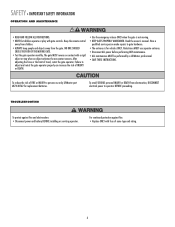
... by a LiftMaster professional. • SAVE THESE INSTRUCTIONS. Failure to operator BEFORE proceeding. TROUBLESHOOTING To protect against fire: • Replace ONLY with fuse of FIRE or INJURY to gate hardware. • The entrance is not moving. • KEEP GATES PROPERLY MAINTAINED. After adjusting the force or the limit of INJURY or DEATH. • Use the emergency release ONLY when the gate is for replacement batteries. Read the ownerʼs manual. To...
... by a LiftMaster professional. • SAVE THESE INSTRUCTIONS. Failure to operator BEFORE proceeding. TROUBLESHOOTING To protect against fire: • Replace ONLY with fuse of FIRE or INJURY to gate hardware. • The entrance is not moving. • KEEP GATES PROPERLY MAINTAINED. After adjusting the force or the limit of INJURY or DEATH. • Use the emergency release ONLY when the gate is for replacement batteries. Read the ownerʼs manual. To...

LA400 Manual
Page 8
... Screws (4) • Anchors (4) • Terminal Block - Six Conductor, 9 feet (2.7 m) • Warning Sign (2) • Battery (2) • Plug-in Transformer (1) LA400-S (SECOND GATE OPERATOR ARM) • Motor Cable - INTRODUCTION » OPERATOR SPECIFICATIONS + CARTON INVENTORY OPERATOR SPECIFICATIONS Operating Cycles: Main Supply (Motor): Current Consumption: Power Consumption: Battery Charger Supply: Maximum Gate Width: Maximum Gate Weight: Protection Class: Travel Speed: Rated Operating Time: Temperature: Main Supply (Control) Dedicated Circuit: Absorbed Power: Protection Fuse...
... Screws (4) • Anchors (4) • Terminal Block - Six Conductor, 9 feet (2.7 m) • Warning Sign (2) • Battery (2) • Plug-in Transformer (1) LA400-S (SECOND GATE OPERATOR ARM) • Motor Cable - INTRODUCTION » OPERATOR SPECIFICATIONS + CARTON INVENTORY OPERATOR SPECIFICATIONS Operating Cycles: Main Supply (Motor): Current Consumption: Power Consumption: Battery Charger Supply: Maximum Gate Width: Maximum Gate Weight: Protection Class: Travel Speed: Rated Operating Time: Temperature: Main Supply (Control) Dedicated Circuit: Absorbed Power: Protection Fuse...
LA400 Manual
Page 21
... 3 Chamberlain loop detectors model LO7LP (not provided). Use knock outs located at the 4 corners of the control box for best radio reception. 1 Open the control box. complete. Lift the door from the hinges and ALARM LOCK GATE 1 setSOL GND MAGR LEARN XMITTER ON OFF LOCK / BIPA RT DELAY BR GR WH YL BL GATE 1 RD SET OPEN LIMIT SET CLOSE LIMIT LEARN LIMITS aside CLOSE EDGE OPEN EDGE/ PHOTO OPEN PHOTO CLOSE PHOTO ACCESSORY POWER 12 V BR GR WH YL BL RD GATE 2 FORCE GATE 2 ON OFF AUTO OPEN...
... 3 Chamberlain loop detectors model LO7LP (not provided). Use knock outs located at the 4 corners of the control box for best radio reception. 1 Open the control box. complete. Lift the door from the hinges and ALARM LOCK GATE 1 setSOL GND MAGR LEARN XMITTER ON OFF LOCK / BIPA RT DELAY BR GR WH YL BL GATE 1 RD SET OPEN LIMIT SET CLOSE LIMIT LEARN LIMITS aside CLOSE EDGE OPEN EDGE/ PHOTO OPEN PHOTO CLOSE PHOTO ACCESSORY POWER 12 V BR GR WH YL BL RD GATE 2 FORCE GATE 2 ON OFF AUTO OPEN...
LA400 Manual
Page 29
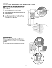
... the operator. WIRING » EARTH GROUND ROD INSTALLATION (OPTIONAL) + CONNECT BATTERIES EARTH GROUND ROD INSTALLATION (OPTIONAL) NOTE: For proper operation, do not connect the earth ground rod to the green screw on the control board. 24 VAC/ INPUT J4 MOV2 POWER C2 C64 U2 BATT 2 BATT 1 USE DEDICATED CIRCUIT 1 BATT 1 BATT 1 Connector BATT 2 Connector 28 ALARM MAGLOCK Z1 GATE 1 ACCESSORY POWER GATE 2 R4 J4 FUSE FUOSPEEN OPEN D15 C2 MOV2 Control Box...
... the operator. WIRING » EARTH GROUND ROD INSTALLATION (OPTIONAL) + CONNECT BATTERIES EARTH GROUND ROD INSTALLATION (OPTIONAL) NOTE: For proper operation, do not connect the earth ground rod to the green screw on the control board. 24 VAC/ INPUT J4 MOV2 POWER C2 C64 U2 BATT 2 BATT 1 USE DEDICATED CIRCUIT 1 BATT 1 BATT 1 Connector BATT 2 Connector 28 ALARM MAGLOCK Z1 GATE 1 ACCESSORY POWER GATE 2 R4 J4 FUSE FUOSPEEN OPEN D15 C2 MOV2 Control Box...
LA400 Manual
Page 31
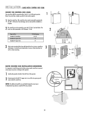
... many operators the installation includes. LEARN LIMITS button SET OPEN LIMIT R2 K2 U4 D4 D2 RESET BUTTON 4 Press the Gate 1 right button to move gate to the desired OPEN position. Control SET OPEN SET CLOSE board will blink). SINGLE ARM LEFT-HAND SIDE PROGRAM OPEN 3 Press the LEARN LIMITS button (SET OPEN LIMIT LED will beep. DIAGNOSTIC GATE 1 SET CLOSE OR SINGLE ARM RIGHT-HAND SIDE PROGRAM OPEN 3 Press the LEARN LIMITS button (SET OPEN LIMIT LED will beep. Control SET OPEN LIMIT SET CLOSE LIMIT board will blink). OPEN LIMIT SET CLOSE LIMIT 7 When gate is now...
... many operators the installation includes. LEARN LIMITS button SET OPEN LIMIT R2 K2 U4 D4 D2 RESET BUTTON 4 Press the Gate 1 right button to move gate to the desired OPEN position. Control SET OPEN SET CLOSE board will blink). SINGLE ARM LEFT-HAND SIDE PROGRAM OPEN 3 Press the LEARN LIMITS button (SET OPEN LIMIT LED will beep. DIAGNOSTIC GATE 1 SET CLOSE OR SINGLE ARM RIGHT-HAND SIDE PROGRAM OPEN 3 Press the LEARN LIMITS button (SET OPEN LIMIT LED will beep. Control SET OPEN LIMIT SET CLOSE LIMIT board will blink). OPEN LIMIT SET CLOSE LIMIT 7 When gate is now...
LA400 Manual
Page 32
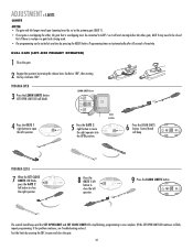
... RESET button. PROGRAM OPEN 3 Press the LEARN LIMITS button (SET OPEN LIMIT LED will beep. Programming times-out automatically after 60 seconds of inactivity. If the problem continues, see Troubleshooting section.) Test the limits by turning the release lever clockwise 180°, then turning the key clockwise 180°. ADJUSTMENT » LIMITS LIMITS NOTES: • The gate with the longer travel span (opening) must be set as the primary gate (GATE 1). • If one gate is overlapping the other gate; Control board SET SET GATE 2 will blink). DUAL GATE...
... RESET button. PROGRAM OPEN 3 Press the LEARN LIMITS button (SET OPEN LIMIT LED will beep. Programming times-out automatically after 60 seconds of inactivity. If the problem continues, see Troubleshooting section.) Test the limits by turning the release lever clockwise 180°, then turning the key clockwise 180°. ADJUSTMENT » LIMITS LIMITS NOTES: • The gate with the longer travel span (opening) must be set as the primary gate (GATE 1). • If one gate is overlapping the other gate; Control board SET SET GATE 2 will blink). DUAL GATE...

LA400 Manual
Page 33
... the RESET button. ADJUSTMENT » LIMITS LIMITS NOTES: • The gate with the longer travel span (opening) must be connected to blink, repeat programming. LEARN LIMITS button SET OPEN LIMIT R2 K2 U4 D4 D2 RESET BUTTON 4 Press the GATE 1 left button to move the left button to open and close the left operator. DIAGNOSTIC 9 Press the LEARN LIMITS SET GATE 1 button. Programming times-out automatically after 60 seconds of inactivity. DIAGNOSTIC GATE 1 SET CLOSE 5 Press the GATE 2 left operator into the OPEN position. Control LIMIT LIMIT FORCE board will blink...
... the RESET button. ADJUSTMENT » LIMITS LIMITS NOTES: • The gate with the longer travel span (opening) must be connected to blink, repeat programming. LEARN LIMITS button SET OPEN LIMIT R2 K2 U4 D4 D2 RESET BUTTON 4 Press the GATE 1 left button to move the left button to open and close the left operator. DIAGNOSTIC 9 Press the LEARN LIMITS SET GATE 1 button. Programming times-out automatically after 60 seconds of inactivity. DIAGNOSTIC GATE 1 SET CLOSE 5 Press the GATE 2 left operator into the OPEN position. Control LIMIT LIMIT FORCE board will blink...

LA400 Manual
Page 34
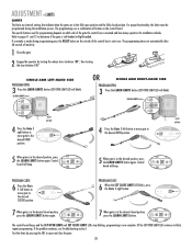
.... TO ADJUST THE FORCE 1 Using the 3-button remote or the Single Button Control (SBC) button on the control board, open and then close the gate. 2 If the gate stops or reverses before reaching the fully open until the operator receives another command from the loops, close edges and close the gate. The TTC is factory set to the mid position. The "TIMER RUNNING LED" will close photoelectric sensors (IR's). 33 TIMER TO CLOSE TIMER TO CLOSE 1 OFF MAX D4 D2 NOTE: Any radio command...
.... TO ADJUST THE FORCE 1 Using the 3-button remote or the Single Button Control (SBC) button on the control board, open and then close the gate. 2 If the gate stops or reverses before reaching the fully open until the operator receives another command from the loops, close edges and close the gate. The TTC is factory set to the mid position. The "TIMER RUNNING LED" will close photoelectric sensors (IR's). 33 TIMER TO CLOSE TIMER TO CLOSE 1 OFF MAX D4 D2 NOTE: Any radio command...
LA400 Manual
Page 35
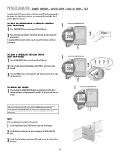
... codes are prohibited, except for changing the code setting or replacing the battery. TO ADD A WIRELESS KEYLESS ENTRY (NOT PROVIDED) 1 Press LEARN XMITTER button and release (LED will stop and reverse on contact with FCC Standards FOR HOME OR OFFICE USE. For highest level of security, we recommend the Security✚® line of this device must accept any adjustments are programmed. THERE ARE NO OTHER USER SERVICEABLE PARTS. LEARN R1 XMITTER 2 To program additional remote controls...
... codes are prohibited, except for changing the code setting or replacing the battery. TO ADD A WIRELESS KEYLESS ENTRY (NOT PROVIDED) 1 Press LEARN XMITTER button and release (LED will stop and reverse on contact with FCC Standards FOR HOME OR OFFICE USE. For highest level of security, we recommend the Security✚® line of this device must accept any adjustments are programmed. THERE ARE NO OTHER USER SERVICEABLE PARTS. LEARN R1 XMITTER 2 To program additional remote controls...
LA400 Manual
Page 37
... control board goes into Sleep Mode). NOTE: Stop jumper is installed within line of sight of the gate. This input functions to OPEN / STOP / CLOSE / STOP in sequence. RESET CONTROL INPUT The control box has a factory installed internal reset button. These terminals are intended for use with a single reset button that is required for normal operation (the Stop LED will command the gate to reset the alarms. This input will NOT stop and common input. Remove only if remotely mounted Stop button...
... control board goes into Sleep Mode). NOTE: Stop jumper is installed within line of sight of the gate. This input functions to OPEN / STOP / CLOSE / STOP in sequence. RESET CONTROL INPUT The control box has a factory installed internal reset button. These terminals are intended for use with a single reset button that is required for normal operation (the Stop LED will command the gate to reset the alarms. This input will NOT stop and common input. Remove only if remotely mounted Stop button...

LA400 Manual
Page 38
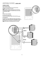
... loop detector manufacturer instructions for connections. SHADOW LOOP INPUT TERMINAL AND COMMON This input protects cars by preventing the gate from moving . Activating this input while the gate is closing gate. ADDITIONAL FEATURES » LOOP INPUTS + PHOTO/EDGE INPUTS (P6-7-8 AND 9) LOOP INPUTS OPEN INPUT AND EXIT LOOP These terminals are intended for use as telephone entry systems, radio receivers (open only applications), exit loop detectors, keypads and 7-day timers may be wired to the open limit...
... loop detector manufacturer instructions for connections. SHADOW LOOP INPUT TERMINAL AND COMMON This input protects cars by preventing the gate from moving . Activating this input while the gate is closing gate. ADDITIONAL FEATURES » LOOP INPUTS + PHOTO/EDGE INPUTS (P6-7-8 AND 9) LOOP INPUTS OPEN INPUT AND EXIT LOOP These terminals are intended for use as telephone entry systems, radio receivers (open only applications), exit loop detectors, keypads and 7-day timers may be wired to the open limit...

LA400 Manual
Page 39
... ON MAGLOCK LEARN R1 XMITTER SINGLE NO DUAL MODE NC EDGE 2 F3 NO NC PHOTO S1 K2 DIAGNOSTIC GATE 1 K1 Q9 SET OPEN LIMIT SET CLOSE LIMIT LEARN LIMITS R2Ø7 Z2Ø R227 J18 U4 R224 Z22 R92 R91 R94 R93 CLOSE EDGE OPEN EDGE/ PHOTO Z9 OPEN PHOTO Z8 CLOSE PHOTO 24V ACCESSORY R9Ø POWER 24V R1Ø1 FORCE GATE 2 TIMER RUNNING BIPART DELAY TIMER TO SINGLE CLOSE BUTTON COM OVLD OVLD OPEN SWITCHED ACCESSORY POWER CONTROL INPUTS GATE 2 BRN GRN...
... ON MAGLOCK LEARN R1 XMITTER SINGLE NO DUAL MODE NC EDGE 2 F3 NO NC PHOTO S1 K2 DIAGNOSTIC GATE 1 K1 Q9 SET OPEN LIMIT SET CLOSE LIMIT LEARN LIMITS R2Ø7 Z2Ø R227 J18 U4 R224 Z22 R92 R91 R94 R93 CLOSE EDGE OPEN EDGE/ PHOTO Z9 OPEN PHOTO Z8 CLOSE PHOTO 24V ACCESSORY R9Ø POWER 24V R1Ø1 FORCE GATE 2 TIMER RUNNING BIPART DELAY TIMER TO SINGLE CLOSE BUTTON COM OVLD OVLD OPEN SWITCHED ACCESSORY POWER CONTROL INPUTS GATE 2 BRN GRN...
LA400 Manual
Page 40
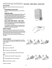
... the motor. 1 2 Turn the key clockwise 180°. PROGRAMMING LIMITS RESET If a mistake is activated for any extended period of the remote control will stop , the alarm will sound (up to normal operation. This locks the release lever. 3 Remove the key and store in a safe place. OPERATOR ALARM The operator alarm will operate the gate during this time. Operator is located on function. ENGAGE 1 Turn the release lever clockwise 180°. OPERATION AND MAINTENANCE » RESET BUTTON + REMOTE CONTROL + MANUAL RELEASE RESET BUTTON The reset button...
... the motor. 1 2 Turn the key clockwise 180°. PROGRAMMING LIMITS RESET If a mistake is activated for any extended period of the remote control will stop , the alarm will sound (up to normal operation. This locks the release lever. 3 Remove the key and store in a safe place. OPERATOR ALARM The operator alarm will operate the gate during this time. Operator is located on function. ENGAGE 1 Turn the release lever clockwise 180°. OPERATION AND MAINTENANCE » RESET BUTTON + REMOTE CONTROL + MANUAL RELEASE RESET BUTTON The reset button...
LA400 Manual
Page 43
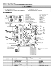
...INPUT #2 17. MASTER GATE JOG 20. FORCE SET 24. ANTENNA INPUT 2. SECOND - FAULT ALARM OUTPUT 15. LIMIT SET 21. Reset Limits SECOND GATE JOG 22. For continued protection against fire and electrocution: • DISCONNECT power and battery BEFORE installing or servicing operator. CONTROL INPUTS/EXIT LOOP 8. TRANSFORMER INPUT 10. CLOSE EDGE 3. DIP SWITCH, S1 18. MASTER OPERATOR ARM CONNECTION 1 ANTENNA CONNECTION 13. LEARN XMITTER 19. TROUBLESHOOTING » WIRING DIAGRAM + DIAGNOSTIC CODES To protect against fire: • Replace ONLY with fuse of same type...
...INPUT #2 17. MASTER GATE JOG 20. FORCE SET 24. ANTENNA INPUT 2. SECOND - FAULT ALARM OUTPUT 15. LIMIT SET 21. Reset Limits SECOND GATE JOG 22. For continued protection against fire and electrocution: • DISCONNECT power and battery BEFORE installing or servicing operator. CONTROL INPUTS/EXIT LOOP 8. TRANSFORMER INPUT 10. CLOSE EDGE 3. DIP SWITCH, S1 18. MASTER OPERATOR ARM CONNECTION 1 ANTENNA CONNECTION 13. LEARN XMITTER 19. TROUBLESHOOTING » WIRING DIAGRAM + DIAGNOSTIC CODES To protect against fire: • Replace ONLY with fuse of same type...

LA400 Manual
Page 44
...Close section for adjustment instructions. ACCESSORY DEVICE NOT WORKING PROPERLY 1) Not installed properly. 2) Enabling Switch not turned on. 3) Loose/disconnected wires. 4) Bad accessory device FIX Battery must be >23 V at battery connection. See Programming Remote instructions. See Programming Limits instructions. Check for obstruction on . Move accessories to resume normal operation. TROUBLESHOOTING » TROUBLESHOOTING CHART FAULT OPERATOR IS DEAD No LED lights are on next page to determine max mA draw for circuit board. GATE STOPS AND REVERSES (Force Reversal) RPM REVERSAL...
...Close section for adjustment instructions. ACCESSORY DEVICE NOT WORKING PROPERLY 1) Not installed properly. 2) Enabling Switch not turned on. 3) Loose/disconnected wires. 4) Bad accessory device FIX Battery must be >23 V at battery connection. See Programming Remote instructions. See Programming Limits instructions. Check for obstruction on . Move accessories to resume normal operation. TROUBLESHOOTING » TROUBLESHOOTING CHART FAULT OPERATOR IS DEAD No LED lights are on next page to determine max mA draw for circuit board. GATE STOPS AND REVERSES (Force Reversal) RPM REVERSAL...
LA400 Manual
Page 46
... Club Road Tucson, AZ 85706 WARRANTY POLICY LIFTMASTER TWO YEAR LIMITED WARRANTY The Chamberlain Group, Inc. REPAIR PARTS » HOW TO ORDER REPAIR PARTS HOW TO ORDER REPAIR PARTS OUR LARGE SERVICE ORGANIZATION SPANS AMERICA FOR INSTALLATION AND SERVICE INFORMATION, CALL OUR TOLL FREE NUMBER 1-800-528-2806 www.liftmaster.com WHEN ORDERING REPAIR PARTS PLEASE SUPPLY THE FOLLOWING INFORMATION: PART NUMBER DESCRIPTION MODEL NUMBER ADDRESS ORDER TO: THE CHAMBERLAIN GROUP, INC. Technical Support Group 6050 S.
... Club Road Tucson, AZ 85706 WARRANTY POLICY LIFTMASTER TWO YEAR LIMITED WARRANTY The Chamberlain Group, Inc. REPAIR PARTS » HOW TO ORDER REPAIR PARTS HOW TO ORDER REPAIR PARTS OUR LARGE SERVICE ORGANIZATION SPANS AMERICA FOR INSTALLATION AND SERVICE INFORMATION, CALL OUR TOLL FREE NUMBER 1-800-528-2806 www.liftmaster.com WHEN ORDERING REPAIR PARTS PLEASE SUPPLY THE FOLLOWING INFORMATION: PART NUMBER DESCRIPTION MODEL NUMBER ADDRESS ORDER TO: THE CHAMBERLAIN GROUP, INC. Technical Support Group 6050 S.


