
LA400 Manual
Page 35
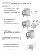
... interference, and (2) this receiver and/or transmitter are prohibited, except for changing the code setting or replacing the battery. Refer to Comply with an obstruction. 34 1 Remote Control LEARN XMITTER Button LEARN XMITTER K5 LEARN R1 XMITTER NOTICE: To comply with FCC and or Industry Canada... recommend the Security✚® line of your choice on the keypad. 1 Remote Control LEARN XMITTER Button LEARN XMITTER K5 LEARN R1 XMITTER 2 3 Press the ENTER button on control board until all remote controls are now erased. PIN Number TO ERASE ALL CODES 1 Press and hold the LEARN...
... interference, and (2) this receiver and/or transmitter are prohibited, except for changing the code setting or replacing the battery. Refer to Comply with an obstruction. 34 1 Remote Control LEARN XMITTER Button LEARN XMITTER K5 LEARN R1 XMITTER NOTICE: To comply with FCC and or Industry Canada... recommend the Security✚® line of your choice on the keypad. 1 Remote Control LEARN XMITTER Button LEARN XMITTER K5 LEARN R1 XMITTER 2 3 Press the ENTER button on control board until all remote controls are now erased. PIN Number TO ERASE ALL CODES 1 Press and hold the LEARN...

LA400 Manual
Page 44
...Arm installation. 1) Obstructed Arm (bottoms out). 2) Bad RPM Sensor. 3) Too much mA pulled off board. Replace control board. See Programming Remote instructions. Replace control board. Connect batteries. Service/replace gate hardware. Rewire desired accessory device to -Close not turned on. 2) Gate has opened on Obstruction ...all Open/Safety devices from obstruction. Check wiring on next page to arm, replace wire if needed. Replace control board. Use reference chart on control board to determine max mA draw for adjustment instructions. Clear gate from obstruction. Operator ...
...Arm installation. 1) Obstructed Arm (bottoms out). 2) Bad RPM Sensor. 3) Too much mA pulled off board. Replace control board. See Programming Remote instructions. Replace control board. Connect batteries. Service/replace gate hardware. Rewire desired accessory device to -Close not turned on. 2) Gate has opened on Obstruction ...all Open/Safety devices from obstruction. Check wiring on next page to arm, replace wire if needed. Replace control board. Use reference chart on control board to determine max mA draw for adjustment instructions. Clear gate from obstruction. Operator ...

LA400 Manual
Page 45
...replacement parts available for your operator, certain components may be added or removed from these lists. 88 22 77 33 44 66 11 55 ITEM PART # 1 K001A6039 2 K75-15480 3 K75-30764 4 K23-19380 5 K74-19499 6 K74-30762 7 K74-30763 8 K76-19446 K74-30941 K001A5747-2 K001A5747 K76-35600 K76-35364 DESCRIPTION QTY Control Board 1 Control... Box & Cover with Gasket 1 Control Board Bracket 1 Reset Switch 1 Antenna 1 Battery 2 Transformer 1 Alarm 1 Not Shown ...
...replacement parts available for your operator, certain components may be added or removed from these lists. 88 22 77 33 44 66 11 55 ITEM PART # 1 K001A6039 2 K75-15480 3 K75-30764 4 K23-19380 5 K74-19499 6 K74-30762 7 K74-30763 8 K76-19446 K74-30941 K001A5747-2 K001A5747 K76-35600 K76-35364 DESCRIPTION QTY Control Board 1 Control... Box & Cover with Gasket 1 Control Board Bracket 1 Reset Switch 1 Antenna 1 Battery 2 Transformer 1 Alarm 1 Not Shown ...
LA400 Push to Open Addendum Manual
Page 2
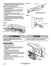
... 12. Secure gate bracket to gate post with 5/16" carriage bolts, flat washers, lock washers and nuts. 13. Install control board and mounting plate. 8. With gate open and operator in retracted position, clamp bracket to detach operator. 9. Adjust operator until... Operator MUST be used. 8. Remove all wire connections for replacement batteries. Remove brackets from electrocution, DISCONNECT electrical power to operator BEFORE proceeding. Open the control box cover. 3. Connect black wires to the control board. Tighten in marked locations for gate post and 11/32"...
... 12. Secure gate bracket to gate post with 5/16" carriage bolts, flat washers, lock washers and nuts. 13. Install control board and mounting plate. 8. With gate open and operator in retracted position, clamp bracket to detach operator. 9. Adjust operator until... Operator MUST be used. 8. Remove all wire connections for replacement batteries. Remove brackets from electrocution, DISCONNECT electrical power to operator BEFORE proceeding. Open the control box cover. 3. Connect black wires to the control board. Tighten in marked locations for gate post and 11/32"...


