
LA400 Manual
Page 28
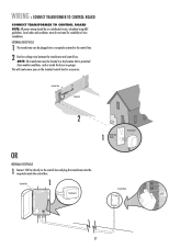
...The transformer can be on a dedicated circuit, calculated using NEC guidelines. Bus 1, 2, 3 Conference Rm 2, 3 Conference Room 1 Conference Room 2 Comp. WIRING » CONNECT TRANSFORMER TO CONTROL BOARD CONNECT TRANSFORMER TO CONTROL BOARD NOTE: All power wiring should be plugged... The transformer must be located in the standard control box for suitability of wire installation. Control Box 1 Transformer Circuit Panel Refer. This will create more space in a dry location that is protected from weather conditions, such as ...Off Off Air (1) Conditioner Main Room LA400 Bathroon.
...The transformer can be on a dedicated circuit, calculated using NEC guidelines. Bus 1, 2, 3 Conference Rm 2, 3 Conference Room 1 Conference Room 2 Comp. WIRING » CONNECT TRANSFORMER TO CONTROL BOARD CONNECT TRANSFORMER TO CONTROL BOARD NOTE: All power wiring should be plugged... The transformer must be located in the standard control box for suitability of wire installation. Control Box 1 Transformer Circuit Panel Refer. This will create more space in a dry location that is protected from weather conditions, such as ...Off Off Air (1) Conditioner Main Room LA400 Bathroon.
LA400 Manual
Page 29
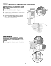
...VAC/ SOLAR INPUT Ground Screw 12 Gauge Wire 3' (0.9 m) Earth Ground Installation (Optional) 8' (2.4 m) CONNECT BATTERIES The batteries are charged in circuit using the transformer (provided). WIRING » EARTH GROUND ROD INSTALLATION (OPTIONAL) + CONNECT BATTERIES EARTH GROUND ROD INSTALLATION (OPTIONAL) NOTE: For proper ...operation, do not connect the earth ground rod to the green screw on the control board. 24 VAC/ INPUT J4 MOV2 POWER C2 C64 U2 BATT 2 BATT 1 USE DEDICATED CIRCUIT 1 BATT 1 BATT 1 Connector BATT 2 Connector 28 Ensure the power wiring ground connection ...
...VAC/ SOLAR INPUT Ground Screw 12 Gauge Wire 3' (0.9 m) Earth Ground Installation (Optional) 8' (2.4 m) CONNECT BATTERIES The batteries are charged in circuit using the transformer (provided). WIRING » EARTH GROUND ROD INSTALLATION (OPTIONAL) + CONNECT BATTERIES EARTH GROUND ROD INSTALLATION (OPTIONAL) NOTE: For proper ...operation, do not connect the earth ground rod to the green screw on the control board. 24 VAC/ INPUT J4 MOV2 POWER C2 C64 U2 BATT 2 BATT 1 USE DEDICATED CIRCUIT 1 BATT 1 BATT 1 Connector BATT 2 Connector 28 Ensure the power wiring ground connection ...

LA400 Manual
Page 44
.... 3) Accessory device wired to -Close not turned on. 2) Gate has opened on next page to -Close section for circuit board. Replace control board. Replace control board. See Installation section of wires. Use reference chart on Obstruction Reversal. 3) Operator in "Party Mode". 4) Constant Open Command... adjustment instructions. See Bipart Delay section for proper installation of accessory. Check proper installation of operator arm. Replace control board. Check wiring on arm, verify arm is given. Clear gate from obstruction. Check for instructions. Voltage must be ...
.... 3) Accessory device wired to -Close not turned on. 2) Gate has opened on next page to -Close section for circuit board. Replace control board. Replace control board. See Installation section of wires. Use reference chart on Obstruction Reversal. 3) Operator in "Party Mode". 4) Constant Open Command... adjustment instructions. See Bipart Delay section for proper installation of accessory. Check proper installation of operator arm. Replace control board. Check wiring on arm, verify arm is given. Clear gate from obstruction. Check for instructions. Voltage must be ...


