Service Manual
Page 24
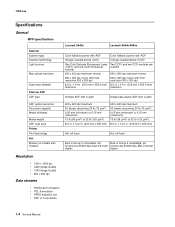
... (120 g/m2) 8.5 in. 7002-xxx Specifications General MFP specifications Scanner Scanner type Scanner technology Light sources Max optical resolution Scan area (flatbed) Scanner ADF ADF type Lexmark X642e Lexmark X644e/X646e Color flatbed scanner with ADF Charge coupled device (CCD) Two Cold Cathode Fluorescent Lamp ...(CCFL) and one CCD module per scanner 600 x 600 dpi maximum (mono) 600...
... (120 g/m2) 8.5 in. 7002-xxx Specifications General MFP specifications Scanner Scanner type Scanner technology Light sources Max optical resolution Scan area (flatbed) Scanner ADF ADF type Lexmark X642e Lexmark X644e/X646e Color flatbed scanner with ADF Charge coupled device (CCD) Two Cold Cathode Fluorescent Lamp ...(CCFL) and one CCD module per scanner 600 x 600 dpi maximum (mono) 600...

Service Manual
Page 49
...-models X644e/X646e" on the touchscreen. 7002-xxx Printer symptoms (continued) Symptom Printer-vertical black bands on page 2-141. Scanner-flatbed symptoms Symptom Flatbed scanner does not recognize paper size. The MFP does not come to "ADF paper length sensor service check-models paper tray X644e/X646e..." on page 2-131. Go to "Flatbed size sensor service check" on page 2-122. Action Go to "High-capacity feeder input ...
...-models X644e/X646e" on the touchscreen. 7002-xxx Printer symptoms (continued) Symptom Printer-vertical black bands on page 2-141. Scanner-flatbed symptoms Symptom Flatbed scanner does not recognize paper size. The MFP does not come to "ADF paper length sensor service check-models paper tray X644e/X646e..." on page 2-131. Go to "Flatbed size sensor service check" on page 2-122. Action Go to "High-capacity feeder input ...
Service Manual
Page 153
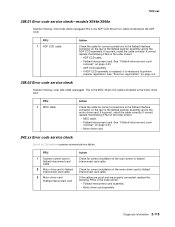
...correct installation of the flatbed scanner assembly and to perform scanner registration. FRU 1 Scanner control card to flatbed inteconnect card cable 2 Motor drive card to flatbed interconnect card cable 3 Motor driver card Flatbed interconnect card Action Check for correct connections to the flatbed interface connector on ... MDC cable Action Check the cable for correct installation of the flatbed scanner assembly and to flatbed interconnect card cable. 7002-xxx 298.01 Error code service check-models X644e/X646e Scanner missing-front side cable unplugged.This is the ADF CCD 36 pin...
...correct installation of the flatbed scanner assembly and to perform scanner registration. FRU 1 Scanner control card to flatbed inteconnect card cable 2 Motor drive card to flatbed interconnect card cable 3 Motor driver card Flatbed interconnect card Action Check for correct connections to the flatbed interface connector on ... MDC cable Action Check the cable for correct installation of the flatbed scanner assembly and to flatbed interconnect card cable. 7002-xxx 298.01 Error code service check-models X644e/X646e Scanner missing-front side cable unplugged.This is the ADF CCD 36 pin...

Service Manual
Page 154
... to both of the home sensor cable before proceeding with this service check. FRU 1 Flatbed scanner CCD drive shafts 2 Flatbed CCD module assembly ribbon cable 3 Flatbed CCD module assembly 4 Flatbed CCD scan motor/ cable Flatbed interface card 5 Flatbed home sensor cable Flatbed home sensor Flatbed interface card Action Check to make sure that both the home sensor and to...
... to both of the home sensor cable before proceeding with this service check. FRU 1 Flatbed scanner CCD drive shafts 2 Flatbed CCD module assembly ribbon cable 3 Flatbed CCD module assembly 4 Flatbed CCD scan motor/ cable Flatbed interface card 5 Flatbed home sensor cable Flatbed home sensor Flatbed interface card Action Check to make sure that both the home sensor and to...

Service Manual
Page 155
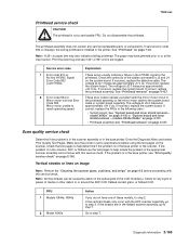
... is located near the home position, to be displayed, replace the complete flatbed scanner assembly. Diagnostic information 2-117 7002-xxx FRU 6 Mechanical interference with the flatbed CCD assembly and the metal locating bracket. Move the flatbed CCD assembly a few inches to perform scanner registration. Bend the bracket upwards 1-2 mm. 3. If the 843.00 error code...
... is located near the home position, to be displayed, replace the complete flatbed scanner assembly. Diagnostic information 2-117 7002-xxx FRU 6 Mechanical interference with the flatbed CCD assembly and the metal locating bracket. Move the flatbed CCD assembly a few inches to perform scanner registration. Bend the bracket upwards 1-2 mm. 3. If the 843.00 error code...
Service Manual
Page 203
....xx Mirror motor lost lock Error Code 935 Mirror motor unable to reach operating speed Explanation These errors usually indicate a failure in the flatbed scanner assembly, go to J2 and J4 on page 2-160. Check the continuity of the CCD module(s). If incorrect, replace the system board.... If incorrect, replace the system board. If incorrect, replace the system board. If correct, replace the FRUs in the printer. model X642e" on page 4-130 or "System board and inner shield removal -models X644e/X646e" on page 4-131. • Printhead assembly See "Printhead removal...
....xx Mirror motor lost lock Error Code 935 Mirror motor unable to reach operating speed Explanation These errors usually indicate a failure in the flatbed scanner assembly, go to J2 and J4 on page 2-160. Check the continuity of the CCD module(s). If incorrect, replace the system board.... If incorrect, replace the system board. If incorrect, replace the system board. If correct, replace the FRUs in the printer. model X642e" on page 4-130 or "System board and inner shield removal -models X644e/X646e" on page 4-131. • Printhead assembly See "Printhead removal...

Service Manual
Page 206
.... (models X644e/X646e) 5 ADF CCD module (models X644e/X646e) Flatbed interconnect card Scanner control card 6 Flatbed CCD module to flatbed interconnect board (J2) cable 7 Flatbed CCD module Action If the problem is with the flatbed scanner assembly, go to step 2. If does not fix the problem, replace the scanner control card. If no problem, is found , go to...
.... (models X644e/X646e) 5 ADF CCD module (models X644e/X646e) Flatbed interconnect card Scanner control card 6 Flatbed CCD module to flatbed interconnect board (J2) cable 7 Flatbed CCD module Action If the problem is with the flatbed scanner assembly, go to step 2. If does not fix the problem, replace the scanner control card. If no problem, is found , go to...

Service Manual
Page 272
A 4-12 Service Manual Scanner right side cover removal Scanner right side cover removal 1. Remove the screw (A). Lift the scan cover (flatbed). 7002-xxx 4.
A 4-12 Service Manual Scanner right side cover removal Scanner right side cover removal 1. Remove the screw (A). Lift the scan cover (flatbed). 7002-xxx 4.

Service Manual
Page 277
Remove the scan cover (flatbed). See "Flatbed contact glass removal" on page 4-11. 2. Unhook the belt from the belt. 6. See "Scan cover (flatbed) removal" on page 4-31 3. Scanner right side cover removal" on page 4-10. 5. 7002-xxx CCD belt removal 1. Repair information 4-17 See "Lift the scan cover (flatbed). Remove the scanner right side cover. See "Scanner left side cover. Remove the flatbed contact glass. Remove the scanner left side cover removal" on page 4-12. 4. Push the CCD belt tension spring to take tension from the motor shaft.
Remove the scan cover (flatbed). See "Flatbed contact glass removal" on page 4-11. 2. Unhook the belt from the belt. 6. See "Scan cover (flatbed) removal" on page 4-31 3. Scanner right side cover removal" on page 4-10. 5. 7002-xxx CCD belt removal 1. Repair information 4-17 See "Lift the scan cover (flatbed). Remove the scanner right side cover. See "Scanner left side cover. Remove the flatbed contact glass. Remove the scanner left side cover removal" on page 4-12. 4. Push the CCD belt tension spring to take tension from the motor shaft.

Service Manual
Page 279
... side cover removal" on page 4-31. 3. Unhook the belt from the belt. 6. Remove the scanner left side cover removal" on page 4-11. 2. Remove the scan cover (flatbed). Remove the scanner right side cover. Repair information 4-19 Remove the flatbed contact glass. Push the CCD belt tension spring toward the motor to take tension from...
... side cover removal" on page 4-31. 3. Unhook the belt from the belt. 6. Remove the scanner left side cover removal" on page 4-11. 2. Remove the scan cover (flatbed). Remove the scanner right side cover. Repair information 4-19 Remove the flatbed contact glass. Push the CCD belt tension spring toward the motor to take tension from...

Service Manual
Page 281
See "Lift the scan cover (flatbed). Remove the scanner left side cover removal" on page 4-10. 4. Remove the scanner right side cover. Scanner right side cover removal" on page 4-11. 2. With pliers, pull firmly to remove the actuator (A). See "Scan cover (flatbed) removal" on page 4-12. 3. 7002-xxx Cover closing actuator removal 1. Remove the scan cover (flatbed). See "Scanner left side cover. A Repair information 4-21
See "Lift the scan cover (flatbed). Remove the scanner left side cover removal" on page 4-10. 4. Remove the scanner right side cover. Scanner right side cover removal" on page 4-11. 2. With pliers, pull firmly to remove the actuator (A). See "Scan cover (flatbed) removal" on page 4-12. 3. 7002-xxx Cover closing actuator removal 1. Remove the scan cover (flatbed). See "Scanner left side cover. A Repair information 4-21

Service Manual
Page 282
A 4-22 Service Manual See "Scan cover (flatbed) removal" on page 4-12. 3. See "Scanner left side cover. Remove the scanner right side cover. Remove the scanner left side cover removal" on page 4-10. 4. Scanner right side cover removal" on page 4-11. 2. See "Lift the scan cover (flatbed). 7002-xxx Cover closed actuator removal 1. With pliers, pull firmly to remove the actuator (A). Remove the scan cover (flatbed).
A 4-22 Service Manual See "Scan cover (flatbed) removal" on page 4-12. 3. See "Scanner left side cover. Remove the scanner right side cover. Remove the scanner left side cover removal" on page 4-10. 4. Scanner right side cover removal" on page 4-11. 2. See "Lift the scan cover (flatbed). 7002-xxx Cover closed actuator removal 1. With pliers, pull firmly to remove the actuator (A). Remove the scan cover (flatbed).

Service Manual
Page 284
... is the same. See "Lift the scan cover (flatbed). Push the flatbed CCD toward the motor to the left side cover. Push the flatbed CCD all the way to take tension from the motor shaft. 7. Remove the scan cover (flatbed). Scanner right side cover removal" on page 4-10. 5. Unhook... the belt from the belt. 6. Remove the flatbed contact glass. See "Flatbed contact glass removal" on page 4-11...
... is the same. See "Lift the scan cover (flatbed). Push the flatbed CCD toward the motor to the left side cover. Push the flatbed CCD all the way to take tension from the motor shaft. 7. Remove the scan cover (flatbed). Scanner right side cover removal" on page 4-10. 5. Unhook... the belt from the belt. 6. Remove the flatbed contact glass. See "Flatbed contact glass removal" on page 4-11...

Service Manual
Page 288
Remove the scan cover (flatbed). See "Scanner left side cover. 7002-xxx Flatbed CCD module assembly removal Illustrations represent models X644e/X646e. See "Scan cover (flatbed) removal" on page 4-12. 4. Remove the scanner right side cover. Scanner right side cover removal" on page 4-11. 2. Remove the scanner left side cover removal" on page 4-31. 3. Unhook the belt from...
Remove the scan cover (flatbed). See "Scanner left side cover. 7002-xxx Flatbed CCD module assembly removal Illustrations represent models X644e/X646e. See "Scan cover (flatbed) removal" on page 4-12. 4. Remove the scanner right side cover. Scanner right side cover removal" on page 4-11. 2. Remove the scanner left side cover removal" on page 4-31. 3. Unhook the belt from...

Service Manual
Page 293
... will be rendered inoperable. See "Scan cover (flatbed) removal" on page 4-31. 3. See "Flatbed contact glass removal" on page 4-11. 2. See "Lift the scan cover (flatbed). It must be returned to the rear scan bracket. Remove the scanner left side cover removal" on page 4-10. ... listed above . Differences are shown side by side. 1. Remove the scanner right side cover. If this procedure is the same. Illustrations represent models X644e/X646e. Remove the scan cover (flatbed). See "Scanner left side cover. Warning: Never install and remove components listed above as...
... will be rendered inoperable. See "Scan cover (flatbed) removal" on page 4-31. 3. See "Flatbed contact glass removal" on page 4-11. 2. See "Lift the scan cover (flatbed). It must be returned to the rear scan bracket. Remove the scanner left side cover removal" on page 4-10. ... listed above . Differences are shown side by side. 1. Remove the scanner right side cover. If this procedure is the same. Illustrations represent models X644e/X646e. Remove the scan cover (flatbed). See "Scanner left side cover. Warning: Never install and remove components listed above as...

Service Manual
Page 295
... side cover removal" on page 4-31. 3. Differences are shown side by side. 1. See "Scanner left side cover. 7002-xxx Flatbed paper length sensor assembly removal Illustrations represent models X644e/X646e. Remove the three screws (A) that attach the hinge support bracket to the rear scan bracket. ...Unless there is an indication, the procedure is the same. Scanner right side cover removal" on page 4-11. 2. See "Scan cover (flatbed) removal" on page 4-12. 4. See "Lift the scan cover...
... side cover removal" on page 4-31. 3. Differences are shown side by side. 1. See "Scanner left side cover. 7002-xxx Flatbed paper length sensor assembly removal Illustrations represent models X644e/X646e. Remove the three screws (A) that attach the hinge support bracket to the rear scan bracket. ...Unless there is an indication, the procedure is the same. Scanner right side cover removal" on page 4-11. 2. See "Scan cover (flatbed) removal" on page 4-12. 4. See "Lift the scan cover...

Service Manual
Page 300
7002-xxx 9. E 11. Pull the scan unit forward to unhook the unit from the printer, and lift the scan unit from the right side (E). Remove the two screws from the printer. Remove the scanner right side cover. Installation note: Remove any clear protective covers from the scanner registration strip and the flatbed white cushion after installation. 4-40 Service Manual "Lift the scan cover (flatbed). Scanner right side cover removal" on page 4-12. 10.
7002-xxx 9. E 11. Pull the scan unit forward to unhook the unit from the printer, and lift the scan unit from the right side (E). Remove the two screws from the printer. Remove the scanner right side cover. Installation note: Remove any clear protective covers from the scanner registration strip and the flatbed white cushion after installation. 4-40 Service Manual "Lift the scan cover (flatbed). Scanner right side cover removal" on page 4-12. 10.

Service Manual
Page 301
... represent models X644e/X646e. See "Flatbed contact glass removal" on page 4-11. 2. Remove the three screws (A) that attach the hinge support bracket to the rear scan bracket. Remove the flatbed contact glass. Remove the scanner right side cover. See "Scanner left side cover removal" on page... 4-12. 4. Unless there is an indication, the procedure is the same. Scanner right side cover removal" on page 4-10. 5. Remove the scanner left side and right...
... represent models X644e/X646e. See "Flatbed contact glass removal" on page 4-11. 2. Remove the three screws (A) that attach the hinge support bracket to the rear scan bracket. Remove the flatbed contact glass. Remove the scanner right side cover. See "Scanner left side cover removal" on page... 4-12. 4. Unless there is an indication, the procedure is the same. Scanner right side cover removal" on page 4-10. 5. Remove the scanner left side and right...

Service Manual
Page 306
... page 4-31. 3. Remove the screw (A). 6. Remove the scanner right side cover. Disconnect the cable (C) from the bracket. 4-46 Service Manual See "Flatbed contact glass removal" on page 4-11. 2. Remove the scanner left side cover removal" on page 4-12. 4. See "Scanner left side cover. Remove the scan cover (flatbed). Scanner right side cover removal" on page 4-10...
... page 4-31. 3. Remove the screw (A). 6. Remove the scanner right side cover. Disconnect the cable (C) from the bracket. 4-46 Service Manual See "Flatbed contact glass removal" on page 4-11. 2. Remove the scanner left side cover removal" on page 4-12. 4. See "Scanner left side cover. Remove the scan cover (flatbed). Scanner right side cover removal" on page 4-10...

Service Manual
Page 315
Pull up on page 4-38. 2. Remove flatbed scanner assembly. See "Flatbed scan assembly removal" on the right side of the upper sub cover. 4. Repair information 4-55 Remove the upper sub cover. Remove screw (A) from right side frame holding upper sub cover. 3. 7002-xxx Upper sub cover removal 1.
Pull up on page 4-38. 2. Remove flatbed scanner assembly. See "Flatbed scan assembly removal" on the right side of the upper sub cover. 4. Repair information 4-55 Remove the upper sub cover. Remove screw (A) from right side frame holding upper sub cover. 3. 7002-xxx Upper sub cover removal 1.


