Service Manual
Page 6
... Fuser assembly removal 4-26 Fuser drive motor assembly removal 4-29 Fuser exit sensor removal 4-30 High-voltage power supply (HVPS) assembly removal 4-31 Image transfer unit (ITU) removal 4-33 Imaging unit (IU) removal 4-35 Low-voltage power supply (LVPS) assembly removal 4-37 Lower frame removal, right and left 4-39 Left lower frame 4-39 Right...
... Fuser assembly removal 4-26 Fuser drive motor assembly removal 4-29 Fuser exit sensor removal 4-30 High-voltage power supply (HVPS) assembly removal 4-31 Image transfer unit (ITU) removal 4-33 Imaging unit (IU) removal 4-35 Low-voltage power supply (LVPS) assembly removal 4-37 Lower frame removal, right and left 4-39 Left lower frame 4-39 Right...
Service Manual
Page 20
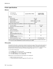
...Menu Settings page: 1. Press Menu ( ) on usage. Printers continuously operating at or near the maximum duty cycle may require service for the imaging unit. • 4800C Q (default) full printer speed • 1200 dpi (reduced printer speed) is standard (soldered) plus 512MB. Select ...pages for replacement of the Menu Settings Page. 5025-2xx, 4xx Printer specifications Memory ✔-Supported ✘-Not supported Lexmark C540n, C543dn Lexmark C544n, C544dn, C544dw Memory Optional slots Standard DIMM sizesa Optional (DDR2) Maximum printer memoryb One slot 128MB 128MB, ...
...Menu Settings page: 1. Press Menu ( ) on usage. Printers continuously operating at or near the maximum duty cycle may require service for the imaging unit. • 4800C Q (default) full printer speed • 1200 dpi (reduced printer speed) is standard (soldered) plus 512MB. Select ...pages for replacement of the Menu Settings Page. 5025-2xx, 4xx Printer specifications Memory ✔-Supported ✘-Not supported Lexmark C540n, C543dn Lexmark C544n, C544dn, C544dw Memory Optional slots Standard DIMM sizesa Optional (DDR2) Maximum printer memoryb One slot 128MB 128MB, ...
Service Manual
Page 33
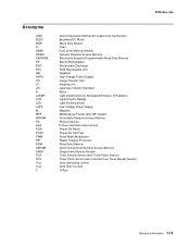
... Only Retract Cyan Dual Inline Memory Module Dynamic Random Access Memory Electrically Erasable Programmable Read-Only Memory ElectroPhotographic Electrostatic Discharge Field Replaceable Unit Gigabyte High-Voltage Power Supply Image Transfer Unit Imaging Unit Japanese Industry Standard Black Light Amplification by Stimulated Emission of Radiation Liquid Crystal Display Light-Emitting Diode Low-Voltage Power Supply Magenta...
... Only Retract Cyan Dual Inline Memory Module Dynamic Random Access Memory Electrically Erasable Programmable Read-Only Memory ElectroPhotographic Electrostatic Discharge Field Replaceable Unit Gigabyte High-Voltage Power Supply Image Transfer Unit Imaging Unit Japanese Industry Standard Black Light Amplification by Stimulated Emission of Radiation Liquid Crystal Display Light-Emitting Diode Low-Voltage Power Supply Magenta...
Service Manual
Page 41
...recurs remove and re-install the cartridge. Try one of the following : • Open and close the front cover. 31.xx Defective Imaging Kit Defective imaging kit. Print the Menu Setting page, and look on page 4-35. This message appears prior to clear the message, and then continue...the printer memory used to store pages is large enough for replacement. It will indicate OK, Replace Black, or Replace Black and Color. See "Imaging unit (IU) removal" on the last page. If the message persists, replace the cartridge with a supported cartridge, and close the top cover. •...
...recurs remove and re-install the cartridge. Try one of the following : • Open and close the front cover. 31.xx Defective Imaging Kit Defective imaging kit. Print the Menu Setting page, and look on page 4-35. This message appears prior to clear the message, and then continue...the printer memory used to store pages is large enough for replacement. It will indicate OK, Replace Black, or Replace Black and Color. See "Imaging unit (IU) removal" on the last page. If the message persists, replace the cartridge with a supported cartridge, and close the top cover. •...
Service Manual
Page 76
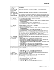
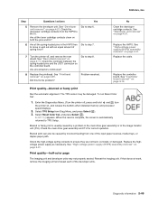
...: a. b. 5025-2xx, 4xx Print quality service check Note: This symptom may require replacement of one or more CRUs (Customer Replaceable Units) designated as supplies or maintenance items, which are low should be replaced. Service tip Before troubleshooting any print quality problems, do the .... - c. To print a menu settings page: a. Print the Print Quality pages to the printer ground. 2-42 Service Manual Inspect the imaging unit for the installed software can cause problems. Incorrect characters could print, and the copy may need to its default levels, do the following ...
...: a. b. 5025-2xx, 4xx Print quality service check Note: This symptom may require replacement of one or more CRUs (Customer Replaceable Units) designated as supplies or maintenance items, which are low should be replaced. Service tip Before troubleshooting any print quality problems, do the .... - c. To print a menu settings page: a. Print the Print Quality pages to the printer ground. 2-42 Service Manual Inspect the imaging unit for the installed software can cause problems. Incorrect characters could print, and the copy may need to its default levels, do the following ...
Service Manual
Page 77
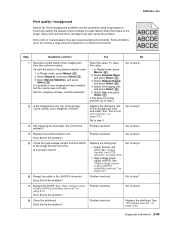
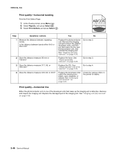
... actions Yes No 1 Read the current status of the imaging unit from the HVPS to the image transfer unit (ITU). Go to step 3. Replace the failing part: • Image transfer unit (ITU). Go to step 4. 3 Did replacing the developer unit correct the problem? Does this fix the problem? Replace ...page 4-31. Problem resolved. Using non-Lexmark toner cartridges may also cause background problems. Some problems occur by using rough paper or incorrectly setting the operator panel settings to rough texture when the texture is possible a new imaging unit was installed, but the counter was not...
... actions Yes No 1 Read the current status of the imaging unit from the HVPS to the image transfer unit (ITU). Go to step 3. Replace the failing part: • Image transfer unit (ITU). Go to step 4. 3 Did replacing the developer unit correct the problem? Does this fix the problem? Replace ...page 4-31. Problem resolved. Using non-Lexmark toner cartridges may also cause background problems. Some problems occur by using rough paper or incorrectly setting the operator panel settings to rough texture when the texture is possible a new imaging unit was installed, but the counter was not...
Service Manual
Page 78
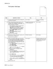
...the printer performs a POR (Power On Reset). Select MISC TESTS in question removed? 2 Print a document that requires all toner cartridges and the imaging unit. 4. Press Select appears. Remove all four colors with just a few characters to step 2. If you press Select before closing the front cover, ...a message appears: Close Cover. See "Main drive gear assembly removal" on page 4-35. See "Imaging unit (IU) removal" on page 4-45. 2-44 Service Manual Press Select. 5. The motor detection process takes about 10 seconds, and stops automatically....
...the printer performs a POR (Power On Reset). Select MISC TESTS in question removed? 2 Print a document that requires all toner cartridges and the imaging unit. 4. Press Select appears. Remove all four colors with just a few characters to step 2. If you press Select before closing the front cover, ...a message appears: Close Cover. See "Main drive gear assembly removal" on page 4-35. See "Imaging unit (IU) removal" on page 4-45. 2-44 Service Manual Press Select. 5. The motor detection process takes about 10 seconds, and stops automatically....
Service Manual
Page 79
..."High-voltage power supply (HVPS) assembly removal" on page 4-11. Replace the controller board. If that does not work, remove the imaging unit and reseat each of spring force? Are all the toner cartridge contacts clean on , and release the buttons when installed memory and processor speed...? 8 Replace the printhead. Diagnostic information 2-45 Enter the Diagnostics Menu. (Turn the printer off , and remove the rear shield. Reseat the imaging unit. Go to ensure they are not bent, corroded, or damaged. Go to TPS Setup. 5025-2xx, 4xx Step Questions / actions Yes 5 Remove ...
..."High-voltage power supply (HVPS) assembly removal" on page 4-11. Replace the controller board. If that does not work, remove the imaging unit and reseat each of spring force? Are all the toner cartridge contacts clean on , and release the buttons when installed memory and processor speed...? 8 Replace the printhead. Diagnostic information 2-45 Enter the Diagnostics Menu. (Turn the printer off , and remove the rear shield. Reseat the imaging unit. Go to ensure they are not bent, corroded, or damaged. Go to TPS Setup. 5025-2xx, 4xx Step Questions / actions Yes 5 Remove ...
Service Manual
Page 80
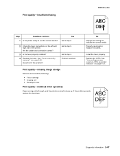
Step Questions / actions Yes No 1 Measure the distance between bands either 34.6 or 94.2 mm? Remove the imaging unit and remove the original developer units, and then put them back into the new photoconductor unit, and reinstall the imaging unit. See "Image transfer unit (ITU) removal" on page 4-35. 2-46 Service Manual Print quality-horizontal line Either the photoconductor...
Step Questions / actions Yes No 1 Measure the distance between bands either 34.6 or 94.2 mm? Remove the imaging unit and remove the original developer units, and then put them back into the new photoconductor unit, and reinstall the imaging unit. See "Image transfer unit (ITU) removal" on page 4-35. 2-46 Service Manual Print quality-horizontal line Either the photoconductor...
Service Manual
Page 81
Does this fix the problem? Problem resolved. No Change the settings to step 4. Replace the LVPS. Print quality-missing image at edge Remove and reseat the following: • Toner cartridge • Imaging unit • Developer units. Yes Go to step 2. 2 Check the fuser connections on page 4-37. Go to indicate the correct media. Properly reconnect...
Does this fix the problem? Problem resolved. No Change the settings to step 4. Replace the LVPS. Print quality-missing image at edge Remove and reseat the following: • Toner cartridge • Imaging unit • Developer units. Yes Go to step 2. 2 Check the fuser connections on page 4-37. Go to indicate the correct media. Properly reconnect...
Service Manual
Page 82
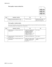
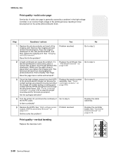
... vertical line ABCDE ABCDE ABCDE Step Questions / actions 1 Replace the photoconductor unit. Yes Inspect the imaging unit by looking at the individual developers and photo conductors. Replace the image transfer unit. Clean or replace the faulty unit. No Go to step 3. Contact your next level of random marks is... cause of support. 2-48 Service Manual Step Questions / actions 1 Is there any loose or foreign material on the imaging unit? 2 Is there any loose or foreign material on the developer roll? 3 Is there any loose or foreign material on the transfer belt?...
... vertical line ABCDE ABCDE ABCDE Step Questions / actions 1 Replace the photoconductor unit. Yes Inspect the imaging unit by looking at the individual developers and photo conductors. Replace the image transfer unit. Clean or replace the faulty unit. No Go to step 3. Contact your next level of random marks is... cause of support. 2-48 Service Manual Step Questions / actions 1 Is there any loose or foreign material on the imaging unit? 2 Is there any loose or foreign material on the developer roll? 3 Is there any loose or foreign material on the transfer belt?...

Service Manual
Page 83
... color of support. Select Menu Settings, and press Select ( ). Contact your next level of the image. Select Imaging Kit, and press Select ( ). See "Imaging unit (IU) removal" on page 4-35. 2 Measure the distance from the Admin Menu, and press Select (...Fuser assembly removal" on page 4-21. Replace the imaging unit or the photoconductor unit. To print a menu settings page: 1. Does the display indicate OK? Replace the imaging unit or the photoconductor unit. See "Developer unit removal" on page 4-26. See "Imaging unit (IU) removal" on the operator panel. 2. At...
... color of support. Select Menu Settings, and press Select ( ). Contact your next level of the image. Select Imaging Kit, and press Select ( ). See "Imaging unit (IU) removal" on page 4-35. 2 Measure the distance from the Admin Menu, and press Select (...Fuser assembly removal" on page 4-21. Replace the imaging unit or the photoconductor unit. To print a menu settings page: 1. Does the display indicate OK? Replace the imaging unit or the photoconductor unit. See "Developer unit removal" on page 4-26. See "Imaging unit (IU) removal" on the operator panel. 2. At...
Service Manual
Page 84
... Replace the transfer contact assembly. See "Controller board removal" on page 4-50. Place the original developers in place when you replace the imaging unit. Does the page have a white vertical band? 3 Check the high-voltage contact from discharging the photoconductors. Did this fix the problem?... cartridge contacts" on page 4-19. Replace the cable assembly. Step Questions / actions Yes No 1 Replace the photoconductor unit (part of the HVPS cable. See "Imaging unit (IU) removal". This will block the laser from the HVPS to step 4. Go to step 2. Problem resolved. ...
... Replace the transfer contact assembly. See "Controller board removal" on page 4-50. Place the original developers in place when you replace the imaging unit. Does the page have a white vertical band? 3 Check the high-voltage contact from discharging the photoconductors. Did this fix the problem?... cartridge contacts" on page 4-19. Replace the cable assembly. Step Questions / actions Yes No 1 Replace the photoconductor unit (part of the HVPS cable. See "Imaging unit (IU) removal". This will block the laser from the HVPS to step 4. Go to step 2. Problem resolved. ...

Service Manual
Page 106
...-inserting the paper tray. The sensor should change state. The sensor should change state. Remove the magenta toner cartridge. Remove all toner cartridges and the imaging unit. 4. Press Select. 5. Press Select appears. 2. Detect Complete. Shine a flashlight on the bin full flag, and then release. The sensor should change state. Select Base Sensor...
...-inserting the paper tray. The sensor should change state. The sensor should change state. Remove the magenta toner cartridge. Remove all toner cartridges and the imaging unit. 4. Press Select. 5. Press Select appears. 2. Detect Complete. Shine a flashlight on the bin full flag, and then release. The sensor should change state. Select Base Sensor...
Service Manual
Page 124
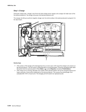
... is damaged (such as a nick or pit), it for the laser beam. This will not be charged properly and heavy amounts of the photoconductor unit. The imaging unit will need to prepare it will cause the charge to be uneven on the photoconductor. 5025-2xx, 4xx Step 1: Charge During the charge step, voltage...
... is damaged (such as a nick or pit), it for the laser beam. This will not be charged properly and heavy amounts of the photoconductor unit. The imaging unit will need to prepare it will cause the charge to be uneven on the photoconductor. 5025-2xx, 4xx Step 1: Charge During the charge step, voltage...

Service Manual
Page 140
... or disconnect any connections between the printer and PCs/peripherals. Notes: • Remove the waste toner bottle, color toner cartridges, imaging unit, and media tray before final tightening. • Some removal procedures require removing cable ties. Open the front cover. 2. Remove the... start all screws before removing other printer parts. See "Right cover assembly removal" on a clean, smooth, and flat surface. The imaging unit should also be carefully set on page 4-10. 4. You must replace cable ties during reassembly to the printer. See "Operator panel removal...
... or disconnect any connections between the printer and PCs/peripherals. Notes: • Remove the waste toner bottle, color toner cartridges, imaging unit, and media tray before final tightening. • Some removal procedures require removing cable ties. Open the front cover. 2. Remove the... start all screws before removing other printer parts. See "Right cover assembly removal" on a clean, smooth, and flat surface. The imaging unit should also be carefully set on page 4-10. 4. You must replace cable ties during reassembly to the printer. See "Operator panel removal...
Service Manual
Page 150
... deflector, and remove the screw (C) holding the ground cable. 4-12 Service Manual See "Right cover assembly removal" on page 4-35. 4. Remove the imaging unit. Remove the right cover assembly. See "Imaging unit (IU) removal" on page 4-10. 2. Remove the rear shield. Disconnect the fan cable from JFAN1 (A) on page 7-3 for the part number. 1. Remove...
... deflector, and remove the screw (C) holding the ground cable. 4-12 Service Manual See "Right cover assembly removal" on page 4-35. 4. Remove the imaging unit. Remove the right cover assembly. See "Imaging unit (IU) removal" on page 4-10. 2. Remove the rear shield. Disconnect the fan cable from JFAN1 (A) on page 7-3 for the part number. 1. Remove...
Service Manual
Page 153
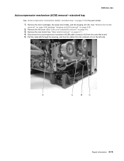
... Disconnect the autocompensator mechanism (ACM) cable connector (A) from the retainers (C) on page 4-35. 2. Remove the toner cartridges, the waste toner bottle, and the imaging unit (IU). See "Rear shield removal" on page 7-5 for the part number. 1. Pull the cable (B) through the opening, and free the cables from the ...controller board. 5. Remove the rear shield. See "Waste toner bottle removal" on page 4-60, and see "Imaging unit (IU) removal" on the left cover. See "Left cover assembly removal" on page 4-6. 3. Repair information 4-15
... Disconnect the autocompensator mechanism (ACM) cable connector (A) from the retainers (C) on page 4-35. 2. Remove the toner cartridges, the waste toner bottle, and the imaging unit (IU). See "Rear shield removal" on page 7-5 for the part number. 1. Pull the cable (B) through the opening, and free the cables from the ...controller board. 5. Remove the rear shield. See "Waste toner bottle removal" on page 4-60, and see "Imaging unit (IU) removal" on the left cover. See "Left cover assembly removal" on page 4-6. 3. Repair information 4-15
Service Manual
Page 159
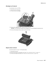
... the front cover. 2. Remove the right cover assembly. Remove the developer unit you need or remove all of the imaging unit. Repair information 4-21 Remove the imaging unit. Remove the waste toner bottle. Warning: Do not touch the underside of them. See "Waste toner bottle ... Remove the toner cartridges. 5025-2xx, 4xx 3. See "Right cover assembly removal" on page 4-60. Developer unit removal The developer units are not FRUs. 1. Duplex sensor removal See "photo sensors" on page 7-7 for the part number. 1. See "Imaging unit (IU) removal". Open the toner access door. 2.
... the front cover. 2. Remove the right cover assembly. Remove the developer unit you need or remove all of the imaging unit. Repair information 4-21 Remove the imaging unit. Remove the waste toner bottle. Warning: Do not touch the underside of them. See "Waste toner bottle ... Remove the toner cartridges. 5025-2xx, 4xx 3. See "Right cover assembly removal" on page 4-60. Developer unit removal The developer units are not FRUs. 1. Duplex sensor removal See "photo sensors" on page 7-7 for the part number. 1. See "Imaging unit (IU) removal". Open the toner access door. 2.
Service Manual
Page 171
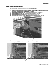
... at this point. 2. Rotate the left spring (B), and pivot the cam away from the barcode after the installation, and it . 5025-2xx, 4xx Image transfer unit (ITU) removal See "Image transfer unit (ITU) assembly" on page 4-10. 3. Remove the waste toner bottle. Write down the number of the ITU path. You will need the... out of the new ITU before installing it is easier to the ITU. 6. See "Right cover assembly removal" on page 7-5 for the part number. 1. See "Imaging unit (IU) removal" on page 4-60. 4. See "Waste toner bottle removal" on page 4-35. 5.
... at this point. 2. Rotate the left spring (B), and pivot the cam away from the barcode after the installation, and it . 5025-2xx, 4xx Image transfer unit (ITU) removal See "Image transfer unit (ITU) assembly" on page 4-10. 3. Remove the waste toner bottle. Write down the number of the ITU path. You will need the... out of the new ITU before installing it is easier to the ITU. 6. See "Right cover assembly removal" on page 7-5 for the part number. 1. See "Imaging unit (IU) removal" on page 4-60. 4. See "Waste toner bottle removal" on page 4-35. 5.


