Lenovo H500s Hardware Maintenance Manual
Page 5
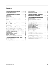
... heat-sink 37 Replacing the CPU 38 Replacing the Wi-Fi card 40 Replacing the front USB/card reader/audio module 41 Replacing the motherboard 42 Chapter 9. Symptom-to-FRU Index . . 19 Hard disk drive boot error 19 Power Supply Problems 19 POST error codes 20 ...Undetermined problems 20 Chapter 7. General Checkout . . . . . 11 Chapter 5. Using the Setup Utility. . . 13 Starting the Lenovo BIOS Setup Utility program . 13 Viewing and changing settings 13 Using passwords 13 Enabling or disabling a device 15 Selecting a startup device 16 Exiting the...
... heat-sink 37 Replacing the CPU 38 Replacing the Wi-Fi card 40 Replacing the front USB/card reader/audio module 41 Replacing the motherboard 42 Chapter 9. Symptom-to-FRU Index . . 19 Hard disk drive boot error 19 Power Supply Problems 19 POST error codes 20 ...Undetermined problems 20 Chapter 7. General Checkout . . . . . 11 Chapter 5. Using the Setup Utility. . . 13 Starting the Lenovo BIOS Setup Utility program . 13 Viewing and changing settings 13 Using passwords 13 Enabling or disabling a device 15 Selecting a startup device 16 Exiting the...
Lenovo H500s Hardware Maintenance Manual
Page 31
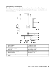
... audio connector Chapter 7. Battery 6 7 8 9 14 13 12 11 10 9. Lenovo H500s 1 23 4 5 15 1. SATA connectors (2) 7. Mini PCI-E slot 15. Front USB connectors (2) 14. Locating connectors, controls and components 25 The following illustration shows the location of connectors and components on the motherboard The motherboard (sometimes called the planar or system board) is the main...
... audio connector Chapter 7. Battery 6 7 8 9 14 13 12 11 10 9. Lenovo H500s 1 23 4 5 15 1. SATA connectors (2) 7. Mini PCI-E slot 15. Front USB connectors (2) 14. Locating connectors, controls and components 25 The following illustration shows the location of connectors and components on the motherboard The motherboard (sometimes called the planar or system board) is the main...

Lenovo H500s Hardware Maintenance Manual
Page 41
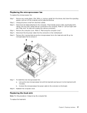
Connect the power cables to the connectors on motherboard. Replacing hardware 35 Step 4. Disconnect all attached devices. Chapter 8. Step 2. Remove the computer cover. Refer to "Left and right view" and "Rear view" for help ... computer. Install the new adapter: a. Replacing the graphic card To replace the graphic card: Step 1. Disconnect the power cables from the connectors on the motherboard.
Connect the power cables to the connectors on motherboard. Replacing hardware 35 Step 4. Disconnect all attached devices. Chapter 8. Step 2. Remove the computer cover. Refer to "Left and right view" and "Rear view" for help ... computer. Install the new adapter: a. Replacing the graphic card To replace the graphic card: Step 1. Disconnect the power cables from the connectors on the motherboard.

Lenovo H500s Hardware Maintenance Manual
Page 42
b. Step 7. Step 6. Step 8. Reattach the metal bracket back into position and secure the graphic card to the same connector on the motherboard. Push the pin that secures the graphic card to remove it. Step 5. Reattach the computer cover. 36 Lenovo H500sHardware Maintenance Manual Slide then insert the new graphic card to the chassis with the screw. Remove the screw that lock the graphic card, and pull it up then slide it out to the chassis, and slide out the metal bracket. To install the new graphic card: a.
b. Step 7. Step 6. Step 8. Reattach the metal bracket back into position and secure the graphic card to the same connector on the motherboard. Push the pin that secures the graphic card to remove it. Step 5. Reattach the computer cover. 36 Lenovo H500sHardware Maintenance Manual Slide then insert the new graphic card to the chassis with the screw. Remove the screw that lock the graphic card, and pull it up then slide it out to the chassis, and slide out the metal bracket. To install the new graphic card: a.
Lenovo H500s Hardware Maintenance Manual
Page 43
... all power cords from the drives, shut down the operating system, and turn off the computer and all cables attached to the connector on the motherboard. Refer to the computer. Remove the 4 screws that are connected to "Left and right view" and "Rear view" for help with 4 screws. To install the...
... all power cords from the drives, shut down the operating system, and turn off the computer and all cables attached to the connector on the motherboard. Refer to the computer. Remove the 4 screws that are connected to "Left and right view" and "Rear view" for help with 4 screws. To install the...
Lenovo H500s Hardware Maintenance Manual
Page 44
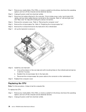
... to "Replacing the microprocessor fan". Refer to "Removing the computer cover". Lift up the screws on the new heat-sink with mounting holes on the motherboard. Step 8. Reattach the microprocessor fan to lay the computer flat. Step 9. Reattach the computer cover. Step 2. Step 3. Step 7. This includes power cords, input/output (I/O) cables... down the operating system, and turn off the computer and all power cords from electrical outlets. Step 1. Unplug all power cords from electrical outlets. 38 Lenovo H500sHardware Maintenance Manual Step 2. c.
... to "Replacing the microprocessor fan". Refer to "Removing the computer cover". Lift up the screws on the new heat-sink with mounting holes on the motherboard. Step 8. Reattach the microprocessor fan to lay the computer flat. Step 9. Reattach the computer cover. Step 2. Step 3. Step 7. This includes power cords, input/output (I/O) cables... down the operating system, and turn off the computer and all power cords from electrical outlets. Step 1. Unplug all power cords from electrical outlets. 38 Lenovo H500sHardware Maintenance Manual Step 2. c.
Lenovo H500s Hardware Maintenance Manual
Page 46
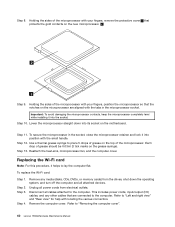
...the microprocessor retainer and lock it into position with your fingers, position the microprocessor so that protects the gold contacts on the motherboard. This includes power cords, input/output (I/O) cables, and any media (disks, CDs, DVDs, or memory cards) from ...microprocessor fan, and the computer cover. Refer to the computer. Disconnect all cables attached to "Removing the computer cover". 40 Lenovo H500sHardware Maintenance Manual Remove the computer cover. Important: To avoid damaging the microprocessor contacts, keep the microprocessor completely level while ...
...the microprocessor retainer and lock it into position with your fingers, position the microprocessor so that protects the gold contacts on the motherboard. This includes power cords, input/output (I/O) cables, and any media (disks, CDs, DVDs, or memory cards) from ...microprocessor fan, and the computer cover. Refer to the computer. Disconnect all cables attached to "Removing the computer cover". 40 Lenovo H500sHardware Maintenance Manual Remove the computer cover. Important: To avoid damaging the microprocessor contacts, keep the microprocessor completely level while ...
Lenovo H500s Hardware Maintenance Manual
Page 47
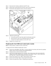
Remove the 2 screws that are connected to the motherboard. Line up the new Wi-Fi card, then insert it helps to "Left and right view" and "Rear view" for help with the 2 screws. Step 4. ... the computer cover". Step 2. Refer to "Removing the front bezel". Refer to "Replacing the optical drive". Chapter 8. Step 7. Step 8. Unplug all cables attached to the motherboard with locating the various connectors.
Remove the 2 screws that are connected to the motherboard. Line up the new Wi-Fi card, then insert it helps to "Left and right view" and "Rear view" for help with the 2 screws. Step 4. ... the computer cover". Step 2. Refer to "Removing the front bezel". Refer to "Replacing the optical drive". Chapter 8. Step 7. Step 8. Unplug all cables attached to the motherboard with locating the various connectors.
Lenovo H500s Hardware Maintenance Manual
Page 48
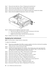
...9. Disconnect the data cables from electrical outlets. c. Step 6. Remove the memory module. Refer to "Replacing the TV-Tuner card". 42 Lenovo H500sHardware Maintenance Manual Refer to "Replacing the heat-sink". Remove the screw that are connected to lay the computer flat. Step 12. ...Disconnect all attached devices. Remove the front bezel. Refer to the chassis. Step 13. Unplug all power cords from the connectors on motherboard. Remove the hard disk drive. Step 8. Remove the computer cover. Remove the TV-Tuner card. Connect the data cables to "...
...9. Disconnect the data cables from electrical outlets. c. Step 6. Remove the memory module. Refer to "Replacing the TV-Tuner card". 42 Lenovo H500sHardware Maintenance Manual Refer to "Replacing the heat-sink". Remove the screw that are connected to lay the computer flat. Step 12. ...Disconnect all attached devices. Remove the front bezel. Refer to the chassis. Step 13. Unplug all power cords from the connectors on motherboard. Remove the hard disk drive. Step 8. Remove the computer cover. Remove the TV-Tuner card. Connect the data cables to "...
Lenovo H500s Hardware Maintenance Manual
Page 49
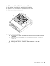
...the Wi-Fi card". Step 17. Install the new motherboard: a. b. Disconnect the all cables to the new motherboard. Refer to the chassis. Step 14. Reattach the hard disk drive, optical drive, graphic card and the TV-Tuner card. Line up the motherboard to remove it with screws. Reattach the memory module,... Wi-Fi card, heat-sink and microprocessor fan to the new motherboard. Chapter 8. c. Reattach the front bezel, computer cover. Connect the all cables from the connectors on the chassis and secure it . Step 18. ...
...the Wi-Fi card". Step 17. Install the new motherboard: a. b. Disconnect the all cables to the new motherboard. Refer to the chassis. Step 14. Reattach the hard disk drive, optical drive, graphic card and the TV-Tuner card. Line up the motherboard to remove it with screws. Reattach the memory module,... Wi-Fi card, heat-sink and microprocessor fan to the new motherboard. Chapter 8. c. Reattach the front bezel, computer cover. Connect the all cables from the connectors on the chassis and secure it . Step 18. ...

Lenovo H5s Series User Guide
Page 39
It provides basic computer functions and supports a variety of devices that are factory-installed or that you can install later. Lenovo H500s 1 23 4 5 6 7 8 9 15 14 13 System fan header Microprocessor fan header Hard disk drive power connector PCI express X 16 adapter slot Clear CMOS jumper Front panel connector 12 11 10 Microprocessor Memory slot SATA connectors (2) Battery LPC debug header System fan header 34 User Guide Identifying parts on the system board The system board (sometimes called the planar or motherboard) is the main circuit board in your computer.
It provides basic computer functions and supports a variety of devices that are factory-installed or that you can install later. Lenovo H500s 1 23 4 5 6 7 8 9 15 14 13 System fan header Microprocessor fan header Hard disk drive power connector PCI express X 16 adapter slot Clear CMOS jumper Front panel connector 12 11 10 Microprocessor Memory slot SATA connectors (2) Battery LPC debug header System fan header 34 User Guide Identifying parts on the system board The system board (sometimes called the planar or motherboard) is the main circuit board in your computer.


