Lenovo H500s Hardware Maintenance Manual
Page 5
...13 Using passwords 13 Enabling or disabling a device 15 Selecting a startup device 16 Exiting the Lenovo BIOS Setup Utility program . . 17 Chapter 6. General information . . . . 45 Additional Service Information 45 © Copyright Lenovo 2013 iii Symptom-to-FRU Index . . 19 Hard disk drive boot error 19 Power ...29 Replacing an optical drive 30 Replacing the hard disk drive 32 Replacing a memory module 33 Replacing the adapter 34 Replacing the graphic card 35 Replacing the microprocessor fan 37 Replacing the heat-sink 37 Replacing the CPU 38 Replacing the Wi-Fi card 40 ...
...13 Using passwords 13 Enabling or disabling a device 15 Selecting a startup device 16 Exiting the Lenovo BIOS Setup Utility program . . 17 Chapter 6. General information . . . . 45 Additional Service Information 45 © Copyright Lenovo 2013 iii Symptom-to-FRU Index . . 19 Hard disk drive boot error 19 Power ...29 Replacing an optical drive 30 Replacing the hard disk drive 32 Replacing a memory module 33 Replacing the adapter 34 Replacing the graphic card 35 Replacing the microprocessor fan 37 Replacing the heat-sink 37 Replacing the CPU 38 Replacing the Wi-Fi card 40 ...

Lenovo H500s Hardware Maintenance Manual
Page 21
... Setup Utility program (See "Starting the Lenovo BIOS Setup Utility program" on page 13.) 2. From the Security menu, select Set Power-On Password and press the Enter key. 3. To set Power-On Password, do the following : 1. Re-type the password to configure system's initiate graphic adapter from booting. The password dialog box...
... Setup Utility program (See "Starting the Lenovo BIOS Setup Utility program" on page 13.) 2. From the Security menu, select Set Power-On Password and press the Enter key. 3. To set Power-On Password, do the following : 1. Re-type the password to configure system's initiate graphic adapter from booting. The password dialog box...
Lenovo H500s Hardware Maintenance Manual
Page 29
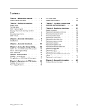
Ethernet connector 6. Cable clip 9. Power connector 8. USB 2.0 connectors (2) 5. WiFi antenna (selected models only) 3. Audio connectors 7. PCI Express X 16 graphics adapter slot (some models are equipped with a graphics card) Chapter 7. Locating connectors, controls and components 23 USB 3.0 connector 2. On-board VGA connector 4. Rear view The following illustration shows the location of connectors and components on the rear of the computer. Lenovo H500s 1.
Ethernet connector 6. Cable clip 9. Power connector 8. USB 2.0 connectors (2) 5. WiFi antenna (selected models only) 3. Audio connectors 7. PCI Express X 16 graphics adapter slot (some models are equipped with a graphics card) Chapter 7. Locating connectors, controls and components 23 USB 3.0 connector 2. On-board VGA connector 4. Rear view The following illustration shows the location of connectors and components on the rear of the computer. Lenovo H500s 1.

Lenovo H500s Hardware Maintenance Manual
Page 41
... the connectors on motherboard. Step 3. Unplug all cables attached to "Removing the computer cover". Remove the computer cover. Replacing hardware 35 Replacing the graphic card To replace the graphic card: Step 1. Refer to the computer. Chapter 8. Disconnect the power cables from the drives, shut down the operating system, and turn off the...
... the connectors on motherboard. Step 3. Unplug all cables attached to "Removing the computer cover". Remove the computer cover. Replacing hardware 35 Replacing the graphic card To replace the graphic card: Step 1. Refer to the computer. Chapter 8. Disconnect the power cables from the drives, shut down the operating system, and turn off the...

Lenovo H500s Hardware Maintenance Manual
Page 42
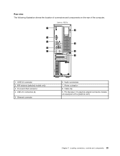
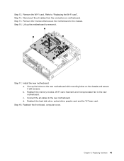
Slide then insert the new graphic card to the chassis with the screw. b. Step 8. Reattach the computer cover. 36 Lenovo H500sHardware Maintenance Manual Push the pin that secures the graphic card to remove it. To install the new graphic card: a. Step 7. Step 6. Step 5. Remove the screw that lock the graphic card, and pull it up then slide it out to the chassis, and slide out the metal bracket. Reattach the metal bracket back into position and secure the graphic card to the same connector on the motherboard.
Slide then insert the new graphic card to the chassis with the screw. b. Step 8. Reattach the computer cover. 36 Lenovo H500sHardware Maintenance Manual Push the pin that secures the graphic card to remove it. To install the new graphic card: a. Step 7. Step 6. Step 5. Remove the screw that lock the graphic card, and pull it up then slide it out to the chassis, and slide out the metal bracket. Reattach the metal bracket back into position and secure the graphic card to the same connector on the motherboard.
Lenovo H500s Hardware Maintenance Manual
Page 48
...off the computer and all cables attached to "Replacing the microprocessor fan". Refer to "Replacing the TV-Tuner card". 42 Lenovo H500sHardware Maintenance Manual Refer to "Replacing the graphic card". Remove the TV-Tuner card. Step 13. Remove the front bezel. Step 6. Remove the heat-sink. Refer to... flat. Reattach the front bezel, computer cover. Remove the computer cover. Refer to "Removing the front bezel". Step 10. Remove the graphic card. Remove the hard disk drive. Remove the power supply. Step 12. Remove any other cables that secures the front USB/card reader...
...off the computer and all cables attached to "Replacing the microprocessor fan". Refer to "Replacing the TV-Tuner card". 42 Lenovo H500sHardware Maintenance Manual Refer to "Replacing the graphic card". Remove the TV-Tuner card. Step 13. Remove the front bezel. Step 6. Remove the heat-sink. Refer to... flat. Reattach the front bezel, computer cover. Remove the computer cover. Refer to "Removing the front bezel". Step 10. Remove the graphic card. Remove the hard disk drive. Remove the power supply. Step 12. Remove any other cables that secures the front USB/card reader...
Lenovo H500s Hardware Maintenance Manual
Page 49
... 15. Step 16. Reattach the memory module, Wi-Fi card, heat-sink and microprocessor fan to the chassis. d. Reattach the hard disk drive, optical drive, graphic card and the TV-Tuner card. Step 18. Lift up the holes on the new motherboard with mounting holes on motherboard. Remove the Wi-Fi...
... 15. Step 16. Reattach the memory module, Wi-Fi card, heat-sink and microprocessor fan to the chassis. d. Reattach the hard disk drive, optical drive, graphic card and the TV-Tuner card. Step 18. Lift up the holes on the new motherboard with mounting holes on motherboard. Remove the Wi-Fi...
Lenovo H5s Series User Guide
Page 8
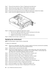
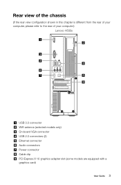
Rear view of the chassis (If the rear view configuration shown in this chapter is different from the rear of your computer, please refer to the rear of your computer.) Lenovo H500s USB 3.0 connector WiFi antenna (selected models only) On-board VGA connector USB 2.0 connectors (2) Ethernet connector Audio connectors Power connector Cable clip PCI Express X 16 graphics adapter slot (some models are equipped with a graphics card) User Guide 3
Rear view of the chassis (If the rear view configuration shown in this chapter is different from the rear of your computer, please refer to the rear of your computer.) Lenovo H500s USB 3.0 connector WiFi antenna (selected models only) On-board VGA connector USB 2.0 connectors (2) Ethernet connector Audio connectors Power connector Cable clip PCI Express X 16 graphics adapter slot (some models are equipped with a graphics card) User Guide 3

Lenovo H5s Series User Guide
Page 9
...-out connector of the device and the audio line-in this connector to attach the computer to attach a device that use the connector on the graphics adapter. Headphone Use this connector to an Ethernet-type local area network. Audio line-in connector on a media card. Audio line-out connector Used to...
...-out connector of the device and the audio line-in this connector to attach the computer to attach a device that use the connector on the graphics adapter. Headphone Use this connector to an Ethernet-type local area network. Audio line-in connector on a media card. Audio line-out connector Used to...

Lenovo H5s Series User Guide
Page 27
Troubleshooting and problem resolution: 1. Check to see if the signal cable to the monitor is securely connected to the connector on the computer graphics card; From here, select the appropriate options to: • Change the desktop background • Select a screen saver • Select Windows color ... screen or no image is displayed on ; Check to see the Help document of the monitor securely to the connector on the computer graphics card. Right-click the desktop anywhere except over an icon, then select Screen resolution from the pop-up menu to change the display ...
Troubleshooting and problem resolution: 1. Check to see if the signal cable to the monitor is securely connected to the connector on the computer graphics card; From here, select the appropriate options to: • Change the desktop background • Select a screen saver • Select Windows color ... screen or no image is displayed on ; Check to see the Help document of the monitor securely to the connector on the computer graphics card. Right-click the desktop anywhere except over an icon, then select Screen resolution from the pop-up menu to change the display ...


