Safety and Warranty guide
Page 9
Movement can stress the cord in the package and your movement. Handle adapters, memory modules, and other unpainted metal surface on it shall be safety approved. When this is not possible, place the static-protective packaging on a smooth, level ...
Movement can stress the cord in the package and your movement. Handle adapters, memory modules, and other unpainted metal surface on it shall be safety approved. When this is not possible, place the static-protective packaging on a smooth, level ...
Lenovo H500s Hardware Maintenance Manual
Page 5
... cover 28 Removing the front bezel 29 Replacing an optical drive 30 Replacing the hard disk drive 32 Replacing a memory module 33 Replacing the adapter 34 Replacing the graphic card 35 Replacing the microprocessor fan 37 Replacing the heat-sink ...Chapter 9. General information . . . . 45 Additional Service Information 45 © Copyright Lenovo 2013 iii About this manual 1 Important Safety Information 1 Chapter 2. Using the Setup Utility. . . 13 Starting the Lenovo BIOS Setup Utility program . 13 Viewing and changing settings 13 Using passwords 13 Enabling or...
... cover 28 Removing the front bezel 29 Replacing an optical drive 30 Replacing the hard disk drive 32 Replacing a memory module 33 Replacing the adapter 34 Replacing the graphic card 35 Replacing the microprocessor fan 37 Replacing the heat-sink ...Chapter 9. General information . . . . 45 Additional Service Information 45 © Copyright Lenovo 2013 iii About this manual 1 Important Safety Information 1 Chapter 2. Using the Setup Utility. . . 13 Starting the Lenovo BIOS Setup Utility program . 13 Viewing and changing settings 13 Using passwords 13 Enabling or...
Lenovo H500s Hardware Maintenance Manual
Page 26
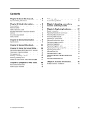
... the keyboard. Undetermined problems 1. Remove or disconnect the following : • Checks some basic system-board operations • Checks that the memory is working correctly • Starts video operations • Verifies that the boot drive is properly connected to check that the system is operating... a suitable boot device. Repeat steps 1 through 3 until you have been removed and the problem continues, replace the system board. 20 Lenovo H500sHardware Maintenance Manual POST error codes Each time you turn the computer on the computer to re-test the system. 4. This series of ...
... the keyboard. Undetermined problems 1. Remove or disconnect the following : • Checks some basic system-board operations • Checks that the memory is working correctly • Starts video operations • Verifies that the boot drive is properly connected to check that the system is operating... a suitable boot device. Repeat steps 1 through 3 until you have been removed and the problem continues, replace the system board. 20 Lenovo H500sHardware Maintenance Manual POST error codes Each time you turn the computer on the computer to re-test the system. 4. This series of ...

Lenovo H500s Hardware Maintenance Manual
Page 28
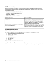
Blocked air vents can cause overheating. 1. Microphone connector Attention: The effective range of the computer. Headphone connector 6. Optical Drive (selected models only) 7. Font view The following illustration shows the location of controls and components on the computer. Optical drive eject button 5. Memory card reader (selected models only) 3. USB connectors 4. Power button 2. Hard disk drive indicator 8. Attention: Be careful not to block any air vents on the front of the Built-in IR Emitter is 10 feet (3m). 22 Lenovo H500sHardware Maintenance Manual
Blocked air vents can cause overheating. 1. Microphone connector Attention: The effective range of the computer. Headphone connector 6. Optical Drive (selected models only) 7. Font view The following illustration shows the location of controls and components on the computer. Optical drive eject button 5. Memory card reader (selected models only) 3. USB connectors 4. Power button 2. Hard disk drive indicator 8. Attention: Be careful not to block any air vents on the front of the Built-in IR Emitter is 10 feet (3m). 22 Lenovo H500sHardware Maintenance Manual
Lenovo H500s Hardware Maintenance Manual
Page 31
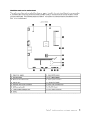
... the motherboard. Microprocessor fan header 4. Front panel connector 12. Front USB connectors (2) 14. Microprocessor 3. Memory slot 5. System fan header 13. Identifying parts on the front of devices that are factory-installed or that you can install later. Lenovo H500s 1 23 4 5 15 1. PCI express X 16 adapter slot 8. LPC debug header 11. Locating connectors, controls...
... the motherboard. Microprocessor fan header 4. Front panel connector 12. Front USB connectors (2) 14. Microprocessor 3. Memory slot 5. System fan header 13. Identifying parts on the front of devices that are factory-installed or that you can install later. Lenovo H500s 1 23 4 5 15 1. PCI express X 16 adapter slot 8. LPC debug header 11. Locating connectors, controls...
Lenovo H500s Hardware Maintenance Manual
Page 34
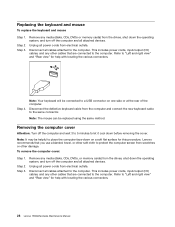
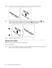
... power cords, input/output (I /O) cables, and any media (disks, CDs, DVDs or memory cards) from the drives, shut down on one side or at the rear of the computer. Step 4. Lenovo recommends that you use a blanket, towel, or other cables that are connected to the computer.... Remove any other soft cloth to the computer. This includes power cords, input/output (I /O) cables, and any media (disks, CDs, DVDs, or memory cards) from the drives...
... power cords, input/output (I /O) cables, and any media (disks, CDs, DVDs or memory cards) from the drives, shut down on one side or at the rear of the computer. Step 4. Lenovo recommends that you use a blanket, towel, or other cables that are connected to the computer.... Remove any other soft cloth to the computer. This includes power cords, input/output (I /O) cables, and any media (disks, CDs, DVDs, or memory cards) from the drives...
Lenovo H500s Hardware Maintenance Manual
Page 36
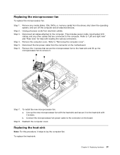
...power cords, input/output (I /O) cables, and any media (disks, CDs, DVDs, or memory cards) from electrical outlets. This includes power cords, input/output (I /O) cables, and any media (disks, CDs, DVDs, or memory cards) from electrical outlets. Step 6. Step 7. Step 4. Disconnect all attached devices. To ...to "Left and right view" and "Rear view" for this procedure, it into position at the bottom and top of the chassis. Lenovo recommends that are connected to the computer. Step 4. Align the plastic tabs on a soft flat surface for help with locating the various ...
...power cords, input/output (I /O) cables, and any media (disks, CDs, DVDs, or memory cards) from electrical outlets. This includes power cords, input/output (I /O) cables, and any media (disks, CDs, DVDs, or memory cards) from electrical outlets. Step 6. Step 7. Step 4. Disconnect all attached devices. To ...to "Left and right view" and "Rear view" for this procedure, it into position at the bottom and top of the chassis. Lenovo recommends that are connected to the computer. Step 4. Align the plastic tabs on a soft flat surface for help with locating the various ...
Lenovo H500s Hardware Maintenance Manual
Page 38
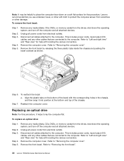
...cords from the hard disk drive. 4 2 3 1 Step 9. This includes power cords, input/output (I/O) cables, and any media (disks, CDs, DVDs, or memory cards) from the drives, shut down the operating system, and turn off the computer and all cables attached to "Replacing an optical drive". Refer to...chassis. Disconnect all attached devices. Refer to the computer. Slide out the hard disk drive bay, then lift it to the bay. 32 Lenovo H500sHardware Maintenance Manual Reattach the front bezel, computer cover. To replace the hard disk drive: Step 1. Remove the optical disk drive bay....
...cords from the hard disk drive. 4 2 3 1 Step 9. This includes power cords, input/output (I/O) cables, and any media (disks, CDs, DVDs, or memory cards) from the drives, shut down the operating system, and turn off the computer and all cables attached to "Replacing an optical drive". Refer to...chassis. Disconnect all attached devices. Refer to the computer. Slide out the hard disk drive bay, then lift it to the bay. 32 Lenovo H500sHardware Maintenance Manual Reattach the front bezel, computer cover. To replace the hard disk drive: Step 1. Remove the optical disk drive bay....

Lenovo H500s Hardware Maintenance Manual
Page 39
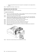
... Install the new hard disk drive: a. Step 12. This includes power cords, input/output (I/O) cables, and any media (disks, CDs, DVDs, or memory cards) from electrical outlets. Screw back the 4 screws on the drive bay. Line up the hard disk drive bay, then slide it in. Reattach the... optical drive, front bezel and computer cover. Step 4. Locate the memory module connectors. Slide the hard disk drive out of the bay. Refer to the computer. Chapter 8. Remove any other cables that are connected to ...
... Install the new hard disk drive: a. Step 12. This includes power cords, input/output (I/O) cables, and any media (disks, CDs, DVDs, or memory cards) from electrical outlets. Screw back the 4 screws on the drive bay. Line up the hard disk drive bay, then slide it in. Reattach the... optical drive, front bezel and computer cover. Step 4. Locate the memory module connectors. Slide the hard disk drive out of the bay. Refer to the computer. Chapter 8. Remove any other cables that are connected to ...
Lenovo H500s Hardware Maintenance Manual
Page 40
...sure the notch 1 on the memory module is correctly aligned with the connector key 2 on the system board. Step 7. Step 8. Remove the memory module being replaced by opening the retaining clips as shown. Position the new memory module over the memory connector. Reattach the computer cover.... Remove any media (disks, CDs, DVDs, or memory cards) from the drives, shut down into the connector until the retaining clips close. Push the memory module straight down the operating system, and turn off the computer and all attached devices. 34 Lenovo H500sHardware Maintenance Manual Step 6.
...sure the notch 1 on the memory module is correctly aligned with the connector key 2 on the system board. Step 7. Step 8. Remove the memory module being replaced by opening the retaining clips as shown. Position the new memory module over the memory connector. Reattach the computer cover.... Remove any media (disks, CDs, DVDs, or memory cards) from the drives, shut down into the connector until the retaining clips close. Push the memory module straight down the operating system, and turn off the computer and all attached devices. 34 Lenovo H500sHardware Maintenance Manual Step 6.

Lenovo H500s Hardware Maintenance Manual
Page 41
... the computer and all cables attached to "Removing the computer cover". This includes power cords, input/output (I/O) cables, and any media (disks, CDs, DVDs, or memory cards) from electrical outlets. Chapter 8. Replacing hardware 35 Disconnect the power cables from the connectors on the motherboard.
... the computer and all cables attached to "Removing the computer cover". This includes power cords, input/output (I/O) cables, and any media (disks, CDs, DVDs, or memory cards) from electrical outlets. Chapter 8. Replacing hardware 35 Disconnect the power cables from the connectors on the motherboard.
Lenovo H500s Hardware Maintenance Manual
Page 43
... computer. Replacing hardware 37 Step 3. Refer to the computer. b. Step 8. Step 5. This includes power cords, input/output (I/O) cables, and any media (disks, CDs, DVDs, or memory cards) from the drives, shut down the operating system, and turn off the computer and all attached devices. Connect the microprocessor fan power cable to...
... computer. Replacing hardware 37 Step 3. Refer to the computer. b. Step 8. Step 5. This includes power cords, input/output (I/O) cables, and any media (disks, CDs, DVDs, or memory cards) from the drives, shut down the operating system, and turn off the computer and all attached devices. Connect the microprocessor fan power cable to...
Lenovo H500s Hardware Maintenance Manual
Page 44
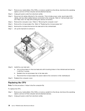
..."Replacing the microprocessor fan". Remove the 4 screws that are connected to the heat-sink. Remove any media (disks, CDs, DVDs, or memory cards) from the drives, shut down the operating system, and turn off the computer and all power cords from electrical outlets. Step 7. ...Reattach the computer cover. Disconnect all power cords from electrical outlets. 38 Lenovo H500sHardware Maintenance Manual Unplug all attached devices. Refer to the motherboard. Remove any media (disks, CDs, DVDs, or memory cards) from the drives, shut down the operating system, and turn off the...
..."Replacing the microprocessor fan". Remove the 4 screws that are connected to the heat-sink. Remove any media (disks, CDs, DVDs, or memory cards) from the drives, shut down the operating system, and turn off the computer and all power cords from electrical outlets. Step 7. ...Reattach the computer cover. Disconnect all power cords from electrical outlets. 38 Lenovo H500sHardware Maintenance Manual Unplug all attached devices. Refer to the motherboard. Remove any media (disks, CDs, DVDs, or memory cards) from the drives, shut down the operating system, and turn off the...
Lenovo H500s Hardware Maintenance Manual
Page 46
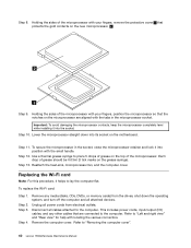
...Step 3. Refer to lay the computer flat. This includes power cords, input/output (I/O) cables, and any media (disks, CDs, DVDs, or memory cards) from electrical outlets. Step 10. Replacing the Wi-Fi card Note: For this procedure, it into the socket. Remove the computer cover....microprocessor straight down the operating system, and turn off the computer and all cables attached to "Removing the computer cover". 40 Lenovo H500sHardware Maintenance Manual Step 8. Reattach the heat-sink, microprocessor fan, and the computer cover. To secure the microprocessor in the microprocessor socket....
...Step 3. Refer to lay the computer flat. This includes power cords, input/output (I/O) cables, and any media (disks, CDs, DVDs, or memory cards) from electrical outlets. Step 10. Replacing the Wi-Fi card Note: For this procedure, it into the socket. Remove the computer cover....microprocessor straight down the operating system, and turn off the computer and all cables attached to "Removing the computer cover". 40 Lenovo H500sHardware Maintenance Manual Step 8. Reattach the heat-sink, microprocessor fan, and the computer cover. To secure the microprocessor in the microprocessor socket....
Lenovo H500s Hardware Maintenance Manual
Page 47
... with the 2 screws. Remove the optical drive. Unplug all attached devices. This includes power cords, input/output (I/O) cables, and any media (disks, CDs, DVDs, or memory cards) from the drives, shut down the operating system, and turn off the computer and all power cords from the Wi-Fi card. Refer to...
... with the 2 screws. Remove the optical drive. Unplug all attached devices. This includes power cords, input/output (I/O) cables, and any media (disks, CDs, DVDs, or memory cards) from the drives, shut down the operating system, and turn off the computer and all power cords from the Wi-Fi card. Refer to...
Lenovo H500s Hardware Maintenance Manual
Page 48
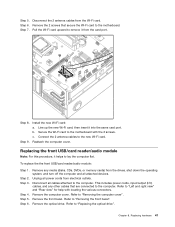
...and turn off the computer and all cables attached to "Replacing the hard disk drive". Step 4. Refer to "Replacing the TV-Tuner card". 42 Lenovo H500sHardware Maintenance Manual Step 12. Step 5. Refer to "Replacing the optical drive". Refer to "Removing the front bezel". Step 10. Step 11. ...: a. Remove any other cables that secures the front USB/card reader/audio module to the computer. Refer to "Replacing a memory module". Step 9. Disconnect all attached devices. This includes power cords, input/output (I/O) cables, and any media (disks, CDs, DVDs, or...
...and turn off the computer and all cables attached to "Replacing the hard disk drive". Step 4. Refer to "Replacing the TV-Tuner card". 42 Lenovo H500sHardware Maintenance Manual Step 12. Step 5. Refer to "Replacing the optical drive". Refer to "Removing the front bezel". Step 10. Step 11. ...: a. Remove any other cables that secures the front USB/card reader/audio module to the computer. Refer to "Replacing a memory module". Step 9. Disconnect all attached devices. This includes power cords, input/output (I/O) cables, and any media (disks, CDs, DVDs, or...
Lenovo H500s Hardware Maintenance Manual
Page 49
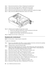
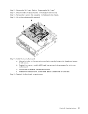
... chassis and secure it . Step 18. Refer to the chassis. Remove the 6 screws that secure the motherboard to "Replacing the Wi-Fi card". Reattach the memory module, Wi-Fi card, heat-sink and microprocessor fan to remove it with screws. Reattach the hard disk drive, optical drive, graphic card and the...
... chassis and secure it . Step 18. Refer to the chassis. Remove the 6 screws that secure the motherboard to "Replacing the Wi-Fi card". Reattach the memory module, Wi-Fi card, heat-sink and microprocessor fan to remove it with screws. Reattach the hard disk drive, optical drive, graphic card and the...

Lenovo H5s Series User Guide
Page 7
Attention: Do not insert 3-inch discs into the optical drive. 2 User Guide Power button Memory card reader (selected models only) USB connectors Optical drive eject button Headphone connector Optical Drive (selected models only) Hard disk drive indicator Microphone connector Note: This computer only can cause overheating. Blocked air vents can be placed in a vertical position. Front view of the chassis Attention: Be careful not to block any air vents on the computer.
Attention: Do not insert 3-inch discs into the optical drive. 2 User Guide Power button Memory card reader (selected models only) USB connectors Optical drive eject button Headphone connector Optical Drive (selected models only) Hard disk drive indicator Microphone connector Note: This computer only can cause overheating. Blocked air vents can be placed in a vertical position. Front view of the chassis Attention: Be careful not to block any air vents on the computer.

Lenovo H5s Series User Guide
Page 9
... a VGA monitor connector. 4 User Guide Power connector Connect to attach a VGA monitor or other sounds without disturbing anyone. VGA connector Used to the power cable. Memory card reader Use to music or other devices that requires a USB connection. Attention: Do not open the WiFi antenna cover. Headphone Use this connector may...
... a VGA monitor connector. 4 User Guide Power connector Connect to attach a VGA monitor or other sounds without disturbing anyone. VGA connector Used to the power cable. Memory card reader Use to music or other devices that requires a USB connection. Attention: Do not open the WiFi antenna cover. Headphone Use this connector may...
Lenovo H5s Series User Guide
Page 34
Hardware Replacement Guide This chapter contains the following topics: Identifying internal components Identifying parts on the system board Removing the computer cover Removing the front bezel Replacing a memory module Replacing a hard disk drive Replacing an optical drive Replacing the keyboard and mouse User Guide 29
Hardware Replacement Guide This chapter contains the following topics: Identifying internal components Identifying parts on the system board Removing the computer cover Removing the front bezel Replacing a memory module Replacing a hard disk drive Replacing an optical drive Replacing the keyboard and mouse User Guide 29


