
Lenovo G470/G475/G570/G575 User Guide V1.0
Page 3
OneKey Rescue system 29 OneKey Rescue system 29 Appendix A. CRU instructions 31 Replacing the battery 31 Replacing the hard disk drive ....33 Replacing memory 37 Removing the optical drive ........40 Trademarks 42 Index 43 i Connecting to know your computer 22 Using Switchable Graphics (specific models only 24 Chapter 3. Getting ...
OneKey Rescue system 29 OneKey Rescue system 29 Appendix A. CRU instructions 31 Replacing the battery 31 Replacing the hard disk drive ....33 Replacing memory 37 Removing the optical drive ........40 Trademarks 42 Index 43 i Connecting to know your computer 22 Using Switchable Graphics (specific models only 24 Chapter 3. Getting ...
Lenovo G470/G475/G570/G575 User Guide V1.0
Page 10
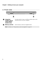
Note: For details, see "Using memory cards (not supplied)" on your computer Front view 1 2 a Integrated wireless device switch (Select models only) b Memory card slot Use this switch to turn on/off the wireless radio of all wireless devices on page 18. 6 Chapter 1. Getting to know your computer. Insert memory cards (not supplied) here.
Note: For details, see "Using memory cards (not supplied)" on your computer Front view 1 2 a Integrated wireless device switch (Select models only) b Memory card slot Use this switch to turn on/off the wireless radio of all wireless devices on page 18. 6 Chapter 1. Getting to know your computer. Insert memory cards (not supplied) here.
Lenovo G470/G475/G570/G575 User Guide V1.0
Page 13
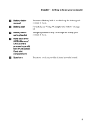
c Battery latch spring loaded The spring-loaded battery latch keeps the battery pack secured in place. b Battery pack For details, see "Using AC adapter and battery" on page 12. Getting to know your computer a Battery latch manual The manual battery latch is used to keep the battery pack secured in place. Chapter 1. d Hard disk drive (HDD)/Memory/ CPU (Central processing unit)/ Mini PCI Express Card slot compartment e Speakers The stereo speakers provide rich and powerful sound. 9
c Battery latch spring loaded The spring-loaded battery latch keeps the battery pack secured in place. b Battery pack For details, see "Using AC adapter and battery" on page 12. Getting to know your computer a Battery latch manual The manual battery latch is used to keep the battery pack secured in place. Chapter 1. d Hard disk drive (HDD)/Memory/ CPU (Central processing unit)/ Mini PCI Express Card slot compartment e Speakers The stereo speakers provide rich and powerful sound. 9
Lenovo G470/G475/G570/G575 User Guide V1.0
Page 22
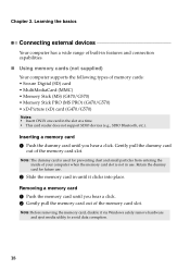
...Windows safely remove hardware and eject media utility to avoid data corruption. 18 Note: The dummy card is not in use . 2 Slide the memory card in until you hear a click. Learning the basics Connecting external devices Your computer has a wide range of built-in the slot at ... preventing dust and small particles from entering the inside of the memory card slot. Chapter 2. Gently pull the dummy card out of memory cards: • Secure Digital (SD) card • MultiMediaCard (MMC) • Memory Stick (MS) (G470/G570) • Memory Stick PRO (MS PRO) (G470/G570) • xD-Picture...
...Windows safely remove hardware and eject media utility to avoid data corruption. 18 Note: The dummy card is not in use . 2 Slide the memory card in until you hear a click. Learning the basics Connecting external devices Your computer has a wide range of built-in the slot at ... preventing dust and small particles from entering the inside of the memory card slot. Chapter 2. Gently pull the dummy card out of memory cards: • Secure Digital (SD) card • MultiMediaCard (MMC) • Memory Stick (MS) (G470/G570) • Memory Stick PRO (MS PRO) (G470/G570) • xD-Picture...
Lenovo G470/G475/G570/G575 User Guide V1.0
Page 38
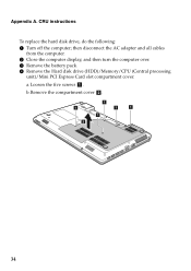
a.Loosen the five screws a . b.Remove the compartment cover b. 1 1 1 1 1 2 34 CRU instructions To replace the hard disk drive, do the following: 1 Turn off the computer; then disconnect the AC adapter and all cables from the computer. 2 Close the computer display, and then turn the computer over. 3 Remove the battery pack. 4 Remove the Hard disk drive (HDD)/Memory/CPU (Central processing unit)/Mini PCI Express Card slot compartment cover. Appendix A.
a.Loosen the five screws a . b.Remove the compartment cover b. 1 1 1 1 1 2 34 CRU instructions To replace the hard disk drive, do the following: 1 Turn off the computer; then disconnect the AC adapter and all cables from the computer. 2 Close the computer display, and then turn the computer over. 3 Remove the battery pack. 4 Remove the Hard disk drive (HDD)/Memory/CPU (Central processing unit)/Mini PCI Express Card slot compartment cover. Appendix A.
Lenovo G470/G475/G570/G575 User Guide V1.0
Page 41
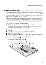
... of the DDR3 SDRAM. 2 Turn off the computer. tricity in your computer. If you incorrectly install optional memory, or install an unsupported memory type, a warning beep will sound when you try to reduce any static elec- Do not touch the contact edge of your... (Central processing unit)/Mini PCI Express Card slot compartment cover. Note: Use only the memory types supported by installing a double-data-rate three synchronous dynamic random access memory (DDR3 SDRAM)-available as an option-in various capacities. To install a DDR3 SDRAM, do the following: 1 Touch a metal table or...
... of the DDR3 SDRAM. 2 Turn off the computer. tricity in your computer. If you incorrectly install optional memory, or install an unsupported memory type, a warning beep will sound when you try to reduce any static elec- Do not touch the contact edge of your... (Central processing unit)/Mini PCI Express Card slot compartment cover. Note: Use only the memory types supported by installing a double-data-rate three synchronous dynamic random access memory (DDR3 SDRAM)-available as an option-in various capacities. To install a DDR3 SDRAM, do the following: 1 Touch a metal table or...
Lenovo G470/G475/G570/G575 User Guide V1.0
Page 42
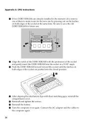
...-45° angle. 8 Push the DDR3 SDRAM inward toward the socket until the latches on both edges of the socket are already installed in the memory slot, remove one by pressing out on the latches on both edges of the socket at the same time. CRU instructions 6 If two DDR3 SDRAMs...
...-45° angle. 8 Push the DDR3 SDRAM inward toward the socket until the latches on both edges of the socket are already installed in the memory slot, remove one by pressing out on the latches on both edges of the socket at the same time. CRU instructions 6 If two DDR3 SDRAMs...
Lenovo G470/G475/G570/G575 User Guide V1.0
Page 43
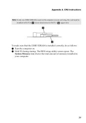
b a To make sure that the DDR3 SDRAM is used on . 2 Hold F2 during startup. The System Memory item shows the total amount of memory installed in SLOT-1 ( : upper slot). The BIOS setup utility screen opens. CRU instructions Note: If only one DDR3 SDRAM is installed correctly, do as follows: 1 Turn the computer on the computer you are servicing, the card must be installed in SLOT-0 ( : lower slot), but not in your computer. 39 Appendix A.
b a To make sure that the DDR3 SDRAM is used on . 2 Hold F2 during startup. The System Memory item shows the total amount of memory installed in SLOT-1 ( : upper slot). The BIOS setup utility screen opens. CRU instructions Note: If only one DDR3 SDRAM is installed correctly, do as follows: 1 Turn the computer on the computer you are servicing, the card must be installed in SLOT-0 ( : lower slot), but not in your computer. 39 Appendix A.
Lenovo G470/G475/G570/G575 User Guide V1.0
Page 45
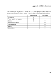
AC adapter Power cord for your computer, and informs you of CRUs (Customer Replaceable Units) for AC adapter Battery Bottom access doors Hard disk drive Memory Optical drive Setup Poster O O O User Guide O O O O O 41 CRU instructions The following table provides a list of where to find replacement instructions. Appendix A.
AC adapter Power cord for your computer, and informs you of CRUs (Customer Replaceable Units) for AC adapter Battery Bottom access doors Hard disk drive Memory Optical drive Setup Poster O O O User Guide O O O O O 41 CRU instructions The following table provides a list of where to find replacement instructions. Appendix A.
Hardware Maintenance Manual
Page 3
... Power-on password 24 Supervisor password 24 Power management 25 Screen blank mode 25 Sleep (standby) mode 25 Hibernation mode 26 Lenovo G470/G475/G570/G575 27 Specifications 27 Status indicators 29 Fn key combinations 31 FRU replacement notices 32 Screw notices 32 Removing and replacing an FRU... 33 1010 Battery pack 34 1020 Dummy cards 35 1030 Optical drive 36 1040 Hard disk drive (HDD)/Memory/CPU (Central processing unit...
... Power-on password 24 Supervisor password 24 Power management 25 Screen blank mode 25 Sleep (standby) mode 25 Hibernation mode 26 Lenovo G470/G475/G570/G575 27 Specifications 27 Status indicators 29 Fn key combinations 31 FRU replacement notices 32 Screw notices 32 Removing and replacing an FRU... 33 1010 Battery pack 34 1020 Dummy cards 35 1030 Optical drive 36 1040 Hard disk drive (HDD)/Memory/CPU (Central processing unit...
Hardware Maintenance Manual
Page 31
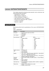
Specifications Feature Processor Core Chipset Bus architecture Graphic memory chip Display Standard memory CMOS RAM Hard disk drive Optical drive Description • Intel Huron River Dual Core i7/i5/i3 • AMD Brazos • Intel ...7mm compatible) SATA II (SATA III capatible), 7200&5400rpm • Internal, 12.7mm (ODD dummy ready) • RAMBO, blueray combo 27 Lenovo G470/G475/G570/G575 Lenovo G470/G475/G570/G575 This chapter presents the following product-specific service references and product-specific parts information: •• "Specifications" on page 27 ••...
Specifications Feature Processor Core Chipset Bus architecture Graphic memory chip Display Standard memory CMOS RAM Hard disk drive Optical drive Description • Intel Huron River Dual Core i7/i5/i3 • AMD Brazos • Intel ...7mm compatible) SATA II (SATA III capatible), 7200&5400rpm • Internal, 12.7mm (ODD dummy ready) • RAMBO, blueray combo 27 Lenovo G470/G475/G570/G575 Lenovo G470/G475/G570/G575 This chapter presents the following product-specific service references and product-specific parts information: •• "Specifications" on page 27 ••...
Hardware Maintenance Manual
Page 41
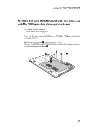
Removal steps of HDD/Memory/CPU/Mini PCI ExpressCard slot compartment cover Note: Loosen the screws 1, but do not remove them. Lenovo G470/G475/G570/G575 1040 Hard disk drive (HDD)/Memory/CPU (Central processing unit)/Mini PCI ExpressCard slot compartment cover For access, remove this FRU: •• "1010 Battery pack" on page 34 Figure 4. Remove the HDD/Memory/CPU/Mini PCI ExpressCard slot compartment cover in the direction shown by arrow 2. 1 1 1 1 1 2 37
Removal steps of HDD/Memory/CPU/Mini PCI ExpressCard slot compartment cover Note: Loosen the screws 1, but do not remove them. Lenovo G470/G475/G570/G575 1040 Hard disk drive (HDD)/Memory/CPU (Central processing unit)/Mini PCI ExpressCard slot compartment cover For access, remove this FRU: •• "1010 Battery pack" on page 34 Figure 4. Remove the HDD/Memory/CPU/Mini PCI ExpressCard slot compartment cover in the direction shown by arrow 2. 1 1 1 1 1 2 37

Hardware Maintenance Manual
Page 42
... by arrow 2. Pull the HDD bracket in a metal frame 3. 1 1 2 38 The hard disk drive is in suspend mode. Figure 5. Lenovo G470/G475/G570/G575 Hardware Maintenance Manual 1050 Hard disk drive For access, remove these FRUs in order: •• "1010 Battery pack" on page 34 •&#...8226; "1040 Hard disk drive (HDD)/Memory/CPU (Central processing unit)/Mini PCI ExpressCard slot compartment cover " on it if possible. •...
... by arrow 2. Pull the HDD bracket in a metal frame 3. 1 1 2 38 The hard disk drive is in suspend mode. Figure 5. Lenovo G470/G475/G570/G575 Hardware Maintenance Manual 1050 Hard disk drive For access, remove these FRUs in order: •• "1010 Battery pack" on page 34 •&#...8226; "1040 Hard disk drive (HDD)/Memory/CPU (Central processing unit)/Mini PCI ExpressCard slot compartment cover " on it if possible. •...

Hardware Maintenance Manual
Page 44
... Battery pack" on page 34 •• "1040 Hard disk drive (HDD)/Memory/CPU (Central processing unit)/Mini PCI ExpressCard slot compartment cover " on the computer you are servicing, the card must be moved. 40 Lenovo G470/G475/G570/G575 Hardware Maintenance Manual 1060 DIMM For access, remove these FRUs in SLOT-1 ( b : upper...
... Battery pack" on page 34 •• "1040 Hard disk drive (HDD)/Memory/CPU (Central processing unit)/Mini PCI ExpressCard slot compartment cover " on the computer you are servicing, the card must be moved. 40 Lenovo G470/G475/G570/G575 Hardware Maintenance Manual 1060 DIMM For access, remove these FRUs in SLOT-1 ( b : upper...

Hardware Maintenance Manual
Page 45
... order: •• "1010 Battery pack" on page 34 •• "1040 Hard disk drive (HDD)/Memory/CPU (Central processing unit)/Mini PCI ExpressCard slot compartment cover " on page 37 Figure 7. Lenovo G470/G475/G570/G575 1070 Fan assembly and Heat Sink assembly For access, remove these FRUs in the direction shown by...
... order: •• "1010 Battery pack" on page 34 •• "1040 Hard disk drive (HDD)/Memory/CPU (Central processing unit)/Mini PCI ExpressCard slot compartment cover " on page 37 Figure 7. Lenovo G470/G475/G570/G575 1070 Fan assembly and Heat Sink assembly For access, remove these FRUs in the direction shown by...

Hardware Maintenance Manual
Page 48
..., avoid any kind of the screw in order: •• "1010 Battery pack" on page 34 •• "1040 Hard disk drive (HDD)/Memory/CPU (Central processing unit)/Mini PCI ExpressCard slot compartment cover " on page 37 •• "1070 Fan assembly and Heat Sink assembly" on page 41... Attention: CPU is extremely sensitive. Figure 8. Lenovo G470/G475/G570/G575 Hardware Maintenance Manual 1080 CPU For access, remove these FRUs in the direction shown by arrow b to secure the CPU. 44
..., avoid any kind of the screw in order: •• "1010 Battery pack" on page 34 •• "1040 Hard disk drive (HDD)/Memory/CPU (Central processing unit)/Mini PCI ExpressCard slot compartment cover " on page 37 •• "1070 Fan assembly and Heat Sink assembly" on page 41... Attention: CPU is extremely sensitive. Figure 8. Lenovo G470/G475/G570/G575 Hardware Maintenance Manual 1080 CPU For access, remove these FRUs in the direction shown by arrow b to secure the CPU. 44
Hardware Maintenance Manual
Page 49
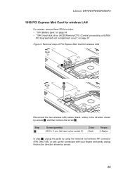
... order: •• "1010 Battery pack" on page 34 •• "1040 Hard disk drive (HDD)/Memory/CPU (Central processing unit)/Mini PCI ExpressCard slot compartment cover " on page 37 Figure 9. Lenovo G470/G475/G570/G575 1090 PCI Express Mini Card for wireless LAN 1 2 Disconnect the two wireless LAN cables (black, white) in...
... order: •• "1010 Battery pack" on page 34 •• "1040 Hard disk drive (HDD)/Memory/CPU (Central processing unit)/Mini PCI ExpressCard slot compartment cover " on page 37 Figure 9. Lenovo G470/G475/G570/G575 1090 PCI Express Mini Card for wireless LAN 1 2 Disconnect the two wireless LAN cables (black, white) in...

Hardware Maintenance Manual
Page 51
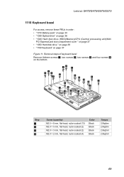
Removal steps of keyboard Remove the screws 1, 2 on page 37 Figure 10. Lenovo G470/G475/G570/G575 1100 Keyboard For access, remove these FRUs in order: •• "1010 Battery pack" on page 34 •• "1040 Hard disk drive (HDD)/Memory/CPU (Central processing unit)/Mini PCI ExpressCard slot compartment cover " on the bottom. 1 1 2 Step 1 2 Screw (quantity) M2.5 × 8 mm, flat-head, nylon-coated (2) M2.5 × 4 mm, flat-head, nylon-coated (1) Color Black Black Torque 2.0kgfcm 2.0kgfcm 47
Removal steps of keyboard Remove the screws 1, 2 on page 37 Figure 10. Lenovo G470/G475/G570/G575 1100 Keyboard For access, remove these FRUs in order: •• "1010 Battery pack" on page 34 •• "1040 Hard disk drive (HDD)/Memory/CPU (Central processing unit)/Mini PCI ExpressCard slot compartment cover " on the bottom. 1 1 2 Step 1 2 Screw (quantity) M2.5 × 8 mm, flat-head, nylon-coated (2) M2.5 × 4 mm, flat-head, nylon-coated (1) Color Black Black Torque 2.0kgfcm 2.0kgfcm 47
Hardware Maintenance Manual
Page 53
Removal steps of keyboard bezel Remove thirteen screws 1, two screws 2, two screws 3 and four screws 4 on page 47 Figure 11. Lenovo G470/G475/G570/G575 1110 Keyboard bezel For access, remove these FRUs in order: •• "1010 Battery pack" on page 34 •• "1030 Optical ...drive" on page 36 •• "1040 Hard disk drive (HDD)/Memory/CPU (Central processing unit)/Mini PCI ExpressCard slot compartment cover " on page...
Removal steps of keyboard bezel Remove thirteen screws 1, two screws 2, two screws 3 and four screws 4 on page 47 Figure 11. Lenovo G470/G475/G570/G575 1110 Keyboard bezel For access, remove these FRUs in order: •• "1010 Battery pack" on page 34 •• "1030 Optical ...drive" on page 36 •• "1040 Hard disk drive (HDD)/Memory/CPU (Central processing unit)/Mini PCI ExpressCard slot compartment cover " on page...
Hardware Maintenance Manual
Page 56
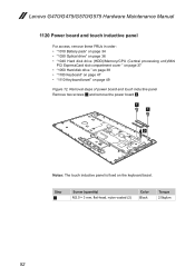
Lenovo G470/G475/G570/G575 Hardware Maintenance Manual 1120 Power board and touch inductive panel For access, remove these FRUs in order: •• "1010 Battery pack" on page 34 •• "1030 Optical drive" on page 36 •• "1040 Hard disk drive (HDD)/Memory/CPU (Central processing unit)/Mini PCI ExpressCard slot...
Lenovo G470/G475/G570/G575 Hardware Maintenance Manual 1120 Power board and touch inductive panel For access, remove these FRUs in order: •• "1010 Battery pack" on page 34 •• "1030 Optical drive" on page 36 •• "1040 Hard disk drive (HDD)/Memory/CPU (Central processing unit)/Mini PCI ExpressCard slot...


