Lenovo G470/G475/G570/G575 User Guide V1.0
Page 10
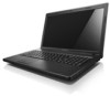
Insert memory cards (not supplied) here. Note: For details, see "Using memory cards (not supplied)" on your computer. Chapter 1. Getting to know your computer Front view 1 2 a Integrated wireless device switch (Select models only) b Memory card slot Use this switch to turn on/off the wireless radio of all wireless devices on page 18. 6
Insert memory cards (not supplied) here. Note: For details, see "Using memory cards (not supplied)" on your computer. Chapter 1. Getting to know your computer Front view 1 2 a Integrated wireless device switch (Select models only) b Memory card slot Use this switch to turn on/off the wireless radio of all wireless devices on page 18. 6
Lenovo G470/G475/G570/G575 User Guide V1.0
Page 13
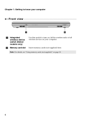
b Battery pack For details, see "Using AC adapter and battery" on page 12. Chapter 1. c Battery latch spring loaded The spring-loaded battery latch keeps the battery pack secured in place. Getting to know your computer a Battery latch manual The manual battery latch is used to keep the battery pack secured in place. d Hard disk drive (HDD)/Memory/ CPU (Central processing unit)/ Mini PCI Express Card slot compartment e Speakers The stereo speakers provide rich and powerful sound. 9
b Battery pack For details, see "Using AC adapter and battery" on page 12. Chapter 1. c Battery latch spring loaded The spring-loaded battery latch keeps the battery pack secured in place. Getting to know your computer a Battery latch manual The manual battery latch is used to keep the battery pack secured in place. d Hard disk drive (HDD)/Memory/ CPU (Central processing unit)/ Mini PCI Express Card slot compartment e Speakers The stereo speakers provide rich and powerful sound. 9
Lenovo G470/G475/G570/G575 User Guide V1.0
Page 22
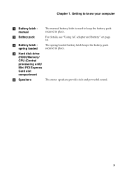
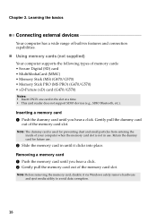
...• Insert ONLY one card in features and connection capabilities. „ Using memory cards (not supplied) Your computer supports the following types of the memory card slot. Removing a memory card 1 Push the memory card until it via Windows safely remove hardware and eject media utility to avoid data... corruption. 18 Note: Before removing the memory card, disable it clicks into place. Note...
...• Insert ONLY one card in features and connection capabilities. „ Using memory cards (not supplied) Your computer supports the following types of the memory card slot. Removing a memory card 1 Push the memory card until it via Windows safely remove hardware and eject media utility to avoid data... corruption. 18 Note: Before removing the memory card, disable it clicks into place. Note...
Lenovo G470/G475/G570/G575 User Guide V1.0
Page 38
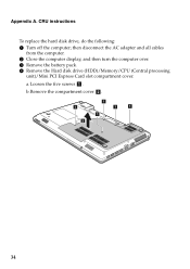
CRU instructions To replace the hard disk drive, do the following: 1 Turn off the computer; then disconnect the AC adapter and all cables from the computer. 2 Close the computer display, and then turn the computer over. 3 Remove the battery pack. 4 Remove the Hard disk drive (HDD)/Memory/CPU (Central processing unit)/Mini PCI Express Card slot compartment cover. Appendix A. b.Remove the compartment cover b. 1 1 1 1 1 2 34 a.Loosen the five screws a .
CRU instructions To replace the hard disk drive, do the following: 1 Turn off the computer; then disconnect the AC adapter and all cables from the computer. 2 Close the computer display, and then turn the computer over. 3 Remove the battery pack. 4 Remove the Hard disk drive (HDD)/Memory/CPU (Central processing unit)/Mini PCI Express Card slot compartment cover. Appendix A. b.Remove the compartment cover b. 1 1 1 1 1 2 34 a.Loosen the five screws a .
Lenovo G470/G475/G570/G575 User Guide V1.0
Page 41
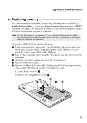
... display, and turn the computer over. 4 Remove the battery again. 5 Remove the Hard disk drive (HDD)/Memory/CPU (Central processing unit)/Mini PCI Express Card slot compartment cover. b.Remove the compartment cover b . 1 1 1 1 1 2 37 tricity in the memory slot of the DDR3 SDRAM. 2 Turn off the computer. To install a DDR3 SDRAM, do the following: 1 Touch...
... display, and turn the computer over. 4 Remove the battery again. 5 Remove the Hard disk drive (HDD)/Memory/CPU (Central processing unit)/Mini PCI Express Card slot compartment cover. b.Remove the compartment cover b . 1 1 1 1 1 2 37 tricity in the memory slot of the DDR3 SDRAM. 2 Turn off the computer. To install a DDR3 SDRAM, do the following: 1 Touch...
Lenovo G470/G475/G570/G575 User Guide V1.0
Page 42
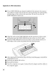
A Reinstall the battery. CRU instructions 6 If two DDR3 SDRAMs are already installed in the memory slot, remove one by pressing out on the latches on both edges of the socket are pushed into the closed position. 2 1 9 After aligning the attachment clips ...
A Reinstall the battery. CRU instructions 6 If two DDR3 SDRAMs are already installed in the memory slot, remove one by pressing out on the latches on both edges of the socket are pushed into the closed position. 2 1 9 After aligning the attachment clips ...
Lenovo G470/G475/G570/G575 User Guide V1.0
Page 43
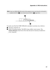
The System Memory item shows the total amount of memory installed in SLOT-1 ( : upper slot). b a To make sure that the DDR3 SDRAM is used on . 2 Hold F2 during startup. CRU instructions Note: If only one DDR3 SDRAM is installed correctly, do as follows: 1 Turn the computer on the computer you are servicing, the card must be installed in SLOT-0 ( : lower slot), but not in your computer. 39 The BIOS setup utility screen opens. Appendix A.
The System Memory item shows the total amount of memory installed in SLOT-1 ( : upper slot). b a To make sure that the DDR3 SDRAM is used on . 2 Hold F2 during startup. CRU instructions Note: If only one DDR3 SDRAM is installed correctly, do as follows: 1 Turn the computer on the computer you are servicing, the card must be installed in SLOT-0 ( : lower slot), but not in your computer. 39 The BIOS setup utility screen opens. Appendix A.
Hardware Maintenance Manual
Page 3
... password 24 Supervisor password 24 Power management 25 Screen blank mode 25 Sleep (standby) mode 25 Hibernation mode 26 Lenovo G470/G475/G570/G575 27 Specifications 27 Status indicators 29 Fn key combinations 31 FRU replacement notices 32 Screw notices 32 Removing and replacing... an FRU 33 1010 Battery pack 34 1020 Dummy cards 35 1030 Optical drive 36 1040 Hard disk drive (HDD)/Memory/CPU (Central processing unit)/Mini PCI ExpressCard slot...
... password 24 Supervisor password 24 Power management 25 Screen blank mode 25 Sleep (standby) mode 25 Hibernation mode 26 Lenovo G470/G475/G570/G575 27 Specifications 27 Status indicators 29 Fn key combinations 31 FRU replacement notices 32 Screw notices 32 Removing and replacing... an FRU 33 1010 Battery pack 34 1020 Dummy cards 35 1030 Optical drive 36 1040 Hard disk drive (HDD)/Memory/CPU (Central processing unit)/Mini PCI ExpressCard slot...
Hardware Maintenance Manual
Page 31
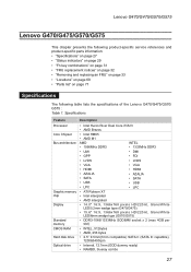
...Parts list" on page 71 Specifications The following table lists the specifications of the Lenovo G470/G475/G570/ G575 : Table 1. Specifications Feature Processor Core Chipset Bus architecture Graphic memory chip Display Standard memory CMOS RAM Hard disk drive Optical drive Description • Intel Huron River Dual ... type (G470/G475) • 15.6" 16:9, 1366x768 pixels HD/220nit, Glare/White LED/6mm wedge type (G570/G575) • DDR3-1066/1333MHz SODIMM socket x 2 (max 4GB per slot) • INTEL, 512bytes • AMD, 256 bytes • 2.5" 9.5mm(7mm compatible) SATA II (SATA III...
...Parts list" on page 71 Specifications The following table lists the specifications of the Lenovo G470/G475/G570/ G575 : Table 1. Specifications Feature Processor Core Chipset Bus architecture Graphic memory chip Display Standard memory CMOS RAM Hard disk drive Optical drive Description • Intel Huron River Dual ... type (G470/G475) • 15.6" 16:9, 1366x768 pixels HD/220nit, Glare/White LED/6mm wedge type (G570/G575) • DDR3-1066/1333MHz SODIMM socket x 2 (max 4GB per slot) • INTEL, 512bytes • AMD, 256 bytes • 2.5" 9.5mm(7mm compatible) SATA II (SATA III...
Hardware Maintenance Manual
Page 41
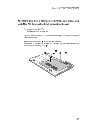
Removal steps of HDD/Memory/CPU/Mini PCI ExpressCard slot compartment cover Note: Loosen the screws 1, but do not remove them. Lenovo G470/G475/G570/G575 1040 Hard disk drive (HDD)/Memory/CPU (Central processing unit)/Mini PCI ExpressCard slot compartment cover For access, remove this FRU: •• "1010 Battery pack" on page 34 Figure 4. Remove the HDD/Memory/CPU/Mini PCI ExpressCard slot compartment cover in the direction shown by arrow 2. 1 1 1 1 1 2 37
Removal steps of HDD/Memory/CPU/Mini PCI ExpressCard slot compartment cover Note: Loosen the screws 1, but do not remove them. Lenovo G470/G475/G570/G575 1040 Hard disk drive (HDD)/Memory/CPU (Central processing unit)/Mini PCI ExpressCard slot compartment cover For access, remove this FRU: •• "1010 Battery pack" on page 34 Figure 4. Remove the HDD/Memory/CPU/Mini PCI ExpressCard slot compartment cover in the direction shown by arrow 2. 1 1 1 1 1 2 37

Hardware Maintenance Manual
Page 42
... is operating or is sensitive to physical shock. Figure 5. Improper handling can cause damages and permanent loss of Hard disk drive Remove two screws 1. Lenovo G470/G475/G570/G575 Hardware Maintenance Manual 1050 Hard disk drive For access, remove these FRUs in order: •• "1010 Battery pack" on page 34 •...
... is operating or is sensitive to physical shock. Figure 5. Improper handling can cause damages and permanent loss of Hard disk drive Remove two screws 1. Lenovo G470/G475/G570/G575 Hardware Maintenance Manual 1050 Hard disk drive For access, remove these FRUs in order: •• "1010 Battery pack" on page 34 •...

Hardware Maintenance Manual
Page 44
... page 37 Figure 6. Lenovo G470/G475/G570/G575 Hardware Maintenance Manual 1060 DIMM For access, remove these FRUs in SLOT-1 ( b : upper slot). Push the DIMM firmly, and pivot it until it is used on the computer you are servicing, the card must be installed in SLOT-0 ( a : lower slot), but not in order...: •• "1010 Battery pack" on page 34 •• "1040 Hard disk drive (HDD)/Memory/CPU (Central processing unit)/Mini PCI ExpressCard slot compartment cover " on both edges of the DIMM into the place. Make sure that it snaps into the socket. b a When ...
... page 37 Figure 6. Lenovo G470/G475/G570/G575 Hardware Maintenance Manual 1060 DIMM For access, remove these FRUs in SLOT-1 ( b : upper slot). Push the DIMM firmly, and pivot it until it is used on the computer you are servicing, the card must be installed in SLOT-0 ( a : lower slot), but not in order...: •• "1010 Battery pack" on page 34 •• "1040 Hard disk drive (HDD)/Memory/CPU (Central processing unit)/Mini PCI ExpressCard slot compartment cover " on both edges of the DIMM into the place. Make sure that it snaps into the socket. b a When ...

Hardware Maintenance Manual
Page 45
Lenovo G470/G475/G570/G575 1070 Fan assembly and Heat Sink assembly For access, remove these FRUs in the direction shown by arrow 3. 1 1 2 2 2 1 2 3 When installing: Make sure that the fan ... spring screws 2. Unplug the connector in order: •• "1010 Battery pack" on page 34 •• "1040 Hard disk drive (HDD)/Memory/CPU (Central processing unit)/Mini PCI ExpressCard slot compartment cover " on page 37 Figure 7. Step 1 2 Screw (quantity) Color M2.0 × 4 mm, flat-head, nylon-coated (3) Silver M2.0 × 3.2 mm...
Lenovo G470/G475/G570/G575 1070 Fan assembly and Heat Sink assembly For access, remove these FRUs in the direction shown by arrow 3. 1 1 2 2 2 1 2 3 When installing: Make sure that the fan ... spring screws 2. Unplug the connector in order: •• "1010 Battery pack" on page 34 •• "1040 Hard disk drive (HDD)/Memory/CPU (Central processing unit)/Mini PCI ExpressCard slot compartment cover " on page 37 Figure 7. Step 1 2 Screw (quantity) Color M2.0 × 4 mm, flat-head, nylon-coated (3) Silver M2.0 × 3.2 mm...

Hardware Maintenance Manual
Page 48
... in the direction shown by arrow 2. 1 a b 2 When installing: Place the CPU on page 41 Attention: CPU is extremely sensitive. Lenovo G470/G475/G570/G575 Hardware Maintenance Manual 1080 CPU For access, remove these FRUs in the direction shown by arrow a , and then rotate the head of the ...screw in order: •• "1010 Battery pack" on page 34 •• "1040 Hard disk drive (HDD)/Memory/CPU (Central processing unit)/Mini PCI ExpressCard slot...
... in the direction shown by arrow 2. 1 a b 2 When installing: Place the CPU on page 41 Attention: CPU is extremely sensitive. Lenovo G470/G475/G570/G575 Hardware Maintenance Manual 1080 CPU For access, remove these FRUs in the direction shown by arrow a , and then rotate the head of the ...screw in order: •• "1010 Battery pack" on page 34 •• "1040 Hard disk drive (HDD)/Memory/CPU (Central processing unit)/Mini PCI ExpressCard slot...
Hardware Maintenance Manual
Page 49
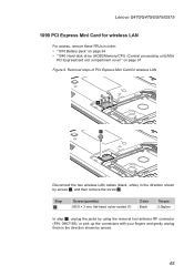
... in order: •• "1010 Battery pack" on page 34 •• "1040 Hard disk drive (HDD)/Memory/CPU (Central processing unit)/Mini PCI ExpressCard slot compartment cover " on page 37 Figure 9. Lenovo G470/G475/G570/G575 1090 PCI Express Mini Card for wireless LAN 1 2 Disconnect the two wireless LAN cables (black, white) in...
... in order: •• "1010 Battery pack" on page 34 •• "1040 Hard disk drive (HDD)/Memory/CPU (Central processing unit)/Mini PCI ExpressCard slot compartment cover " on page 37 Figure 9. Lenovo G470/G475/G570/G575 1090 PCI Express Mini Card for wireless LAN 1 2 Disconnect the two wireless LAN cables (black, white) in...

Hardware Maintenance Manual
Page 51
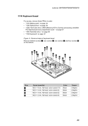
Removal steps of keyboard Remove the screws 1, 2 on page 37 Figure 10. Lenovo G470/G475/G570/G575 1100 Keyboard For access, remove these FRUs in order: •• "1010 Battery pack" on page 34 •• "1040 Hard disk drive (HDD)/Memory/CPU (Central processing unit)/Mini PCI ExpressCard slot compartment cover " on the bottom. 1 1 2 Step 1 2 Screw (quantity) M2.5 × 8 mm, flat-head, nylon-coated (2) M2.5 × 4 mm, flat-head, nylon-coated (1) Color Black Black Torque 2.0kgfcm 2.0kgfcm 47
Removal steps of keyboard Remove the screws 1, 2 on page 37 Figure 10. Lenovo G470/G475/G570/G575 1100 Keyboard For access, remove these FRUs in order: •• "1010 Battery pack" on page 34 •• "1040 Hard disk drive (HDD)/Memory/CPU (Central processing unit)/Mini PCI ExpressCard slot compartment cover " on the bottom. 1 1 2 Step 1 2 Screw (quantity) M2.5 × 8 mm, flat-head, nylon-coated (2) M2.5 × 4 mm, flat-head, nylon-coated (1) Color Black Black Torque 2.0kgfcm 2.0kgfcm 47
Hardware Maintenance Manual
Page 53
Lenovo G470/G475/G570/G575 1110 Keyboard bezel For access, remove these FRUs in order: •• "1010 Battery pack" on page 34 •• "1030 Optical drive" on page 36 •• "1040 Hard disk drive (HDD)/Memory/CPU (Central processing unit)/Mini PCI ExpressCard slot compartment cover " on page 37 •• "1050...
Lenovo G470/G475/G570/G575 1110 Keyboard bezel For access, remove these FRUs in order: •• "1010 Battery pack" on page 34 •• "1030 Optical drive" on page 36 •• "1040 Hard disk drive (HDD)/Memory/CPU (Central processing unit)/Mini PCI ExpressCard slot compartment cover " on page 37 •• "1050...
Hardware Maintenance Manual
Page 56
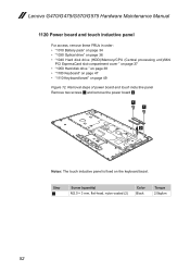
... Lenovo G470/G475/G570/G575 Hardware Maintenance Manual 1120 Power board and touch inductive panel For access, remove these FRUs in order: •• "1010 Battery pack" on page 34 •• "1030 Optical drive" on page 36 •• "1040 Hard disk drive (HDD)/Memory/CPU (Central processing unit)/Mini PCI ExpressCard slot...
... Lenovo G470/G475/G570/G575 Hardware Maintenance Manual 1120 Power board and touch inductive panel For access, remove these FRUs in order: •• "1010 Battery pack" on page 34 •• "1030 Optical drive" on page 36 •• "1040 Hard disk drive (HDD)/Memory/CPU (Central processing unit)/Mini PCI ExpressCard slot...
Hardware Maintenance Manual
Page 57
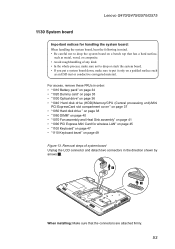
..."1020 Dummy card" on page 35 •• "1030 Optical drive" on page 36 •• "1040 Hard disk drive (HDD)/Memory/CPU (Central processing unit)/Mini PCI ExpressCard slot compartment cover " on page 37 •• "1050 Hard disk drive " on page 38 •• "1060 DIMM" on page ...; If you put a system board down, make sure to drop the system board on a bench top that the connectors are attached firmly. 53 Lenovo G470/G475/G570/G575 1130 System board Important notices for wireless LAN" on page 45 •• "1100 Keyboard" on page 47 •• "1110 Keyboard bezel...
..."1020 Dummy card" on page 35 •• "1030 Optical drive" on page 36 •• "1040 Hard disk drive (HDD)/Memory/CPU (Central processing unit)/Mini PCI ExpressCard slot compartment cover " on page 37 •• "1050 Hard disk drive " on page 38 •• "1060 DIMM" on page ...; If you put a system board down, make sure to drop the system board on a bench top that the connectors are attached firmly. 53 Lenovo G470/G475/G570/G575 1130 System board Important notices for wireless LAN" on page 45 •• "1100 Keyboard" on page 47 •• "1110 Keyboard bezel...
Hardware Maintenance Manual
Page 60
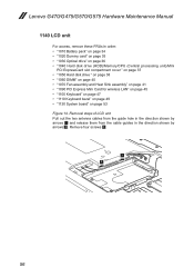
Lenovo G470/G475/G570/G575 Hardware Maintenance Manual 1140 LCD unit For access, remove these FRUs in the direction shown by arrows 1 and release them from the cable guides in ...;• "1020 Dummy card" on page 35 •• "1030 Optical drive" on page 36 •• "1040 Hard disk drive (HDD)/Memory/CPU (Central processing unit)/Mini PCI ExpressCard slot compartment cover " on page 37 •• "1050 Hard disk drive " on page 38 •• "1060 DIMM" on page 40...
Lenovo G470/G475/G570/G575 Hardware Maintenance Manual 1140 LCD unit For access, remove these FRUs in the direction shown by arrows 1 and release them from the cable guides in ...;• "1020 Dummy card" on page 35 •• "1030 Optical drive" on page 36 •• "1040 Hard disk drive (HDD)/Memory/CPU (Central processing unit)/Mini PCI ExpressCard slot compartment cover " on page 37 •• "1050 Hard disk drive " on page 38 •• "1060 DIMM" on page 40...


