
Service Manual
Page 1
CAUTION BEFORE SERVICING THE CHASSIS, READ THE SAFETY PRECAUTIONS IN THIS MANUAL. R *Same looking with new chassis *Issue Date; 2004. 06 website:http://biz.LGservice.com e-mail:http://www.LGEservice.com/techsup.html LCD TV SERVICE MANUAL CHASSIS : ML-041B MODEL: RT-15LA70(RT-15LA70 Rev A) *( ) ID LABEL Model No.
CAUTION BEFORE SERVICING THE CHASSIS, READ THE SAFETY PRECAUTIONS IN THIS MANUAL. R *Same looking with new chassis *Issue Date; 2004. 06 website:http://biz.LGservice.com e-mail:http://www.LGEservice.com/techsup.html LCD TV SERVICE MANUAL CHASSIS : ML-041B MODEL: RT-15LA70(RT-15LA70 Rev A) *( ) ID LABEL Model No.
Service Manual
Page 2
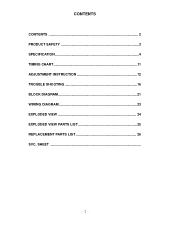
SHEET CONTENTS CONTENTS 2 PRODUCT SAFETY 3 SPECIFICATION 4 TIMING CHART 11 ADJUSTMENT INSTRUCTION 12 TROUBLE SHOOTING 16 BLOCK DIAGRAM 21 WIRING DIAGRAM 23 EXPLODED VIEW 24 EXPLODED VIEW PARTS LIST 25 REPLACEMENT PARTS LIST 26 SVC.
SHEET CONTENTS CONTENTS 2 PRODUCT SAFETY 3 SPECIFICATION 4 TIMING CHART 11 ADJUSTMENT INSTRUCTION 12 TROUBLE SHOOTING 16 BLOCK DIAGRAM 21 WIRING DIAGRAM 23 EXPLODED VIEW 24 EXPLODED VIEW PARTS LIST 25 REPLACEMENT PARTS LIST 26 SVC.
Service Manual
Page 3
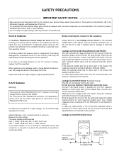
...(Antenna Cold Check) With the instrument AC plug removed from electrical shocks. If the exposed metallic part has a return path to be sure the set must not exceed 0.75 volt RMS which is the High Voltage Section and the LCD PANEL. Connect 1.5K/10watt resistor in the Schematic Diagram and Replacement Parts List. It will also protect the receiver and it with the same components...
...(Antenna Cold Check) With the instrument AC plug removed from electrical shocks. If the exposed metallic part has a return path to be sure the set must not exceed 0.75 volt RMS which is the High Voltage Section and the LCD PANEL. Connect 1.5K/10watt resistor in the Schematic Diagram and Replacement Parts List. It will also protect the receiver and it with the same components...
Service Manual
Page 4
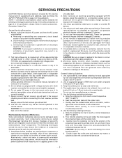
.... Use an appropriate gauge of RMA resin-core solder composed of this service manual. b. Heat the component lead until immediately before you are packaged with ES devices, place the assembly on page 3 of your body by touching a known earth ground. CAUTION: Work quickly to solder or unsolder ES devices. 4. CAUTION: A wrong part substitution or incorrect polarity installation of...
.... Use an appropriate gauge of RMA resin-core solder composed of this service manual. b. Heat the component lead until immediately before you are packaged with ES devices, place the assembly on page 3 of your body by touching a known earth ground. CAUTION: Work quickly to solder or unsolder ES devices. 4. CAUTION: A wrong part substitution or incorrect polarity installation of...

Service Manual
Page 5
...Removal/Replacement 1. Power Output, Transistor Device Removal/Replacement 1. If they are inserted and then bent flat against the circuit foil pad and solder it. 3. Securely crimp the leads of any excess jumper wire. Circuit Board Foil Repair Excessive heat applied to separate from or "lift-off excess lead. 6. At IC Connections To repair a defective copper pattern at least 1/4 inch... 3. Remove the defective transistor by clipping its leads as close as possible to ensure that is encountered. Remove the heat sink mounting screw (if so equipped). 3. Replace heat sink...
...Removal/Replacement 1. Power Output, Transistor Device Removal/Replacement 1. If they are inserted and then bent flat against the circuit foil pad and solder it. 3. Securely crimp the leads of any excess jumper wire. Circuit Board Foil Repair Excessive heat applied to separate from or "lift-off excess lead. 6. At IC Connections To repair a defective copper pattern at least 1/4 inch... 3. Remove the defective transistor by clipping its leads as close as possible to ensure that is encountered. Remove the heat sink mounting screw (if so equipped). 3. Replace heat sink...

Service Manual
Page 6
... Color Depth Size [mm] Surface Treatment Operating Mode Back light Unit R/T Typ. 2 Maker Type ActiveDisplay Area Pixel Pitch [mm] Electrical Interface Color Depth Size [mm] Surface Treatment Operating Mode Back light Unit R/T Typ. 3 Maker Type ActiveDisplay Area Pixel Pitch [mm] Electrical Interface Color Depth Size [mm] Surface Treatment Operating Mode Back light Unit R/T Typ. SPECIFICATION NOTE : Specifications and others are subject to ML-041B chassis. 2. Specification LPL TFT Color LCD Module 15.0 inches...
... Color Depth Size [mm] Surface Treatment Operating Mode Back light Unit R/T Typ. 2 Maker Type ActiveDisplay Area Pixel Pitch [mm] Electrical Interface Color Depth Size [mm] Surface Treatment Operating Mode Back light Unit R/T Typ. 3 Maker Type ActiveDisplay Area Pixel Pitch [mm] Electrical Interface Color Depth Size [mm] Surface Treatment Operating Mode Back light Unit R/T Typ. SPECIFICATION NOTE : Specifications and others are subject to ML-041B chassis. 2. Specification LPL TFT Color LCD Module 15.0 inches...
Service Manual
Page 7
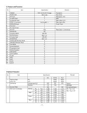
Item 1 Viewing Angle 2 Luminance 3 Contrast Ratio 4 CIE Color Coordinates R/L, U/D Luminance(cd/ ) Variation WHITE WX WY RED Wr Yr Green Xg Yg Blue Xb Yb Specification LPL 450 1.3 400 Typ. 0.289 Typ. 0.304 Typ. 0.619 Typ. 0....Input 5 Component input 6 PERI TV Connector 7 RGB(VGA)Input 8 H/p input 9 PC Sound input 10 RS-232 11 Discrete IR 12 2 Carrier Stereo 13 NICAM Stereo 14 2 Carrier Dual 15 NICAM Dual 16 DW(Double Window) Mode 17 MW(Multi Window) Mode 18 Film Mode 19 Noise Reduction 20 Progressive Scan 21 Motion Detection 22 SRS WOW 23 wivel Speaker 24 Ez-pip 25 ARC...
Item 1 Viewing Angle 2 Luminance 3 Contrast Ratio 4 CIE Color Coordinates R/L, U/D Luminance(cd/ ) Variation WHITE WX WY RED Wr Yr Green Xg Yg Blue Xb Yb Specification LPL 450 1.3 400 Typ. 0.289 Typ. 0.304 Typ. 0.619 Typ. 0....Input 5 Component input 6 PERI TV Connector 7 RGB(VGA)Input 8 H/p input 9 PC Sound input 10 RS-232 11 Discrete IR 12 2 Carrier Stereo 13 NICAM Stereo 14 2 Carrier Dual 15 NICAM Dual 16 DW(Double Window) Mode 17 MW(Multi Window) Mode 18 Film Mode 19 Noise Reduction 20 Progressive Scan 21 Motion Detection 22 SRS WOW 23 wivel Speaker 24 Ez-pip 25 ARC...
Service Manual
Page 8
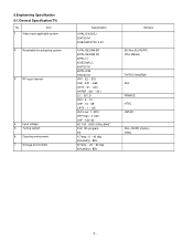
Item 1 Video input applicable system 2 Receivable broadcasting system 3 RF input channel 4 Input voltage 5 Tuning system 6 Operting environment 7 Storage environment Specification 1)PAL-D/K,B/G,I 2)NTSC-M 3)SECAM NTSC 4.43' 1)PAL/SECAM BG 2)PAL/SECAM DK 3)PAL I/I 4)SECAM L/L' 5)NTSC M 6)PAL-N/M 7)NTSC M VHF :... 100 - 240V/ 50Hz,60HZ FVS 100 program FS 1)Temp : 0 ~ 40 deg 2)Humidity : 85% 3)Temp : -20 ~ 60 deg 4)Humidity : 85% Remark EU/Non-EU(RZ/RT) (PAL Market) 7)NTSC Area(RM) PAL FRANCE NTSC JAPAN PAL, 200PR.(Option) NTSC 6.Engineering Specification 6-1.General Specification(TV) No.
Item 1 Video input applicable system 2 Receivable broadcasting system 3 RF input channel 4 Input voltage 5 Tuning system 6 Operting environment 7 Storage environment Specification 1)PAL-D/K,B/G,I 2)NTSC-M 3)SECAM NTSC 4.43' 1)PAL/SECAM BG 2)PAL/SECAM DK 3)PAL I/I 4)SECAM L/L' 5)NTSC M 6)PAL-N/M 7)NTSC M VHF :... 100 - 240V/ 50Hz,60HZ FVS 100 program FS 1)Temp : 0 ~ 40 deg 2)Humidity : 85% 3)Temp : -20 ~ 60 deg 4)Humidity : 85% Remark EU/Non-EU(RZ/RT) (PAL Market) 7)NTSC Area(RM) PAL FRANCE NTSC JAPAN PAL, 200PR.(Option) NTSC 6.Engineering Specification 6-1.General Specification(TV) No.

Service Manual
Page 9
Item 1 Power Supply Normal Stand By Suspend Mode DPM Off Mode Cut-off Switch off ITEM 2 D-SUB Pin Configuraion 3 Control Function Specification H/V Sync On/On Off/On On/Off Off/Off - 1: RED 3: Blue: 5: S.T(GND) 7: Green GND 9: N.C 11: ID0(GND) 13: H-Sync 15: SCL 1) Contrast/Brightness 2) H-Position/V-Position 3) Tracking : Clock/ Phase 4) Auto Configure RESET Video Power Consumption Active 55W 1W Off 1W 1W - 0W PBP SWAP...
Item 1 Power Supply Normal Stand By Suspend Mode DPM Off Mode Cut-off Switch off ITEM 2 D-SUB Pin Configuraion 3 Control Function Specification H/V Sync On/On Off/On On/Off Off/Off - 1: RED 3: Blue: 5: S.T(GND) 7: Green GND 9: N.C 11: ID0(GND) 13: H-Sync 15: SCL 1) Contrast/Brightness 2) H-Position/V-Position 3) Tracking : Clock/ Phase 4) Auto Configure RESET Video Power Consumption Active 55W 1W Off 1W 1W - 0W PBP SWAP...
Service Manual
Page 10
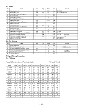
...Input Frame Rate 6-4. Audio Input Distortion 6. Audio Output S/N 13. RGB Input Resolution, Horizontal 18. Audio Input Dynamic Range 7. The Others NO Item 1 Search Sensitivity 2 Soft Ware Functionality Test 3 REMOCON Working Sensitivity, Straight 4 REMOCON Working Sensitivity, T/B/L/R 5 Closed Caption Sensitivity 6 Teletext Sensitivity 7. Video Output S/N 10. RGB Input Resolution, Vertical 17. Audio Input S/N 5. Video Output Frequency Response 9. Power NO Item 1. Video Input Level 2. 6-3. Audio Output Level 11. Signal Timing(Resolution) 7-1. PC Mode...
...Input Frame Rate 6-4. Audio Input Distortion 6. Audio Output S/N 13. RGB Input Resolution, Horizontal 18. Audio Input Dynamic Range 7. The Others NO Item 1 Search Sensitivity 2 Soft Ware Functionality Test 3 REMOCON Working Sensitivity, Straight 4 REMOCON Working Sensitivity, T/B/L/R 5 Closed Caption Sensitivity 6 Teletext Sensitivity 7. Video Output S/N 10. RGB Input Resolution, Vertical 17. Audio Input S/N 5. Video Output Frequency Response 9. Power NO Item 1. Video Input Level 2. 6-3. Audio Output Level 11. Signal Timing(Resolution) 7-1. PC Mode...
Service Manual
Page 12
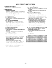
... input. Using the Pattern Generator (801GF, VG819) adjust WXGA (1280 X 768) for resolution and Color Bar signals for the pattern. Connect the DDC automation equipment to D-Sub Jack. Application Object This instruction is set to convert into the adjustment mode using the adjustment (SVC) remote controller and pressing the IN-START Key, and then press VOL+ Key at the AutoGain menu. However when errors occur, it should be adjusted manually. 2.2 Auto...
... input. Using the Pattern Generator (801GF, VG819) adjust WXGA (1280 X 768) for resolution and Color Bar signals for the pattern. Connect the DDC automation equipment to D-Sub Jack. Application Object This instruction is set to convert into the adjustment mode using the adjustment (SVC) remote controller and pressing the IN-START Key, and then press VOL+ Key at the AutoGain menu. However when errors occur, it should be adjusted manually. 2.2 Auto...
Service Manual
Page 14
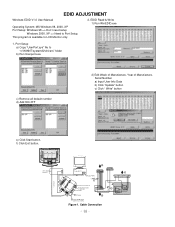
EDID ADJUSTMENT Windows EDID V1.0 User Manual Operating System: MS Windows 98, 2000, XP Port Setup: Windows 98 => Don't need setup Windows 2000, XP => Need to LCD Monitor only. 2. EDID Read & Write 1) Run WinEDID.exe 1. This program is available to Port Setup. Cable Connection Video Signal Generator Control Line PARALLEL Not used RS232C C VGS A MONITOR B V-SYNC ST POWER IBM Compatible PC 15 10 5 PARALLEL PORT OFF ON 5V F Power inlet (required) 220 Power Select Switch (110V/220V) Power LED E ST Switch A 9 11...
EDID ADJUSTMENT Windows EDID V1.0 User Manual Operating System: MS Windows 98, 2000, XP Port Setup: Windows 98 => Don't need setup Windows 2000, XP => Need to LCD Monitor only. 2. EDID Read & Write 1) Run WinEDID.exe 1. This program is available to Port Setup. Cable Connection Video Signal Generator Control Line PARALLEL Not used RS232C C VGS A MONITOR B V-SYNC ST POWER IBM Compatible PC 15 10 5 PARALLEL PORT OFF ON 5V F Power inlet (required) 220 Power Select Switch (110V/220V) Power LED E ST Switch A 9 11...
Service Manual
Page 15
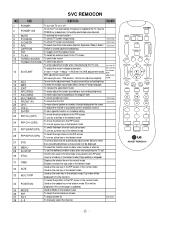
... be displayed if the current page is supplied to the TV. (Use the POWER key to closed caption broadcasting 8 TXT To toggle on/off 2 POWER ON To turn the TV on the screen. To adjust the volume or accurately control a specific function. To check TV screen image easily. Shortcut keys To check TV screen sound easily To select size of the PIP screen in the normal mode 34 POSITION Used as Mode in...
... be displayed if the current page is supplied to the TV. (Use the POWER key to closed caption broadcasting 8 TXT To toggle on/off 2 POWER ON To turn the TV on the screen. To adjust the volume or accurately control a specific function. To check TV screen image easily. Shortcut keys To check TV screen sound easily To select size of the PIP screen in the normal mode 34 POSITION Used as Mode in...

Service Manual
Page 17
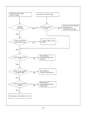
No Raster :[B]Process Check LED Status on display unit Fail Repeat A PROCESS Check L900,L901 L902,L903 Fail Pass Check the input/ Output of IC901 Fail Pass Check inverter Connector or inverter Fail Pass Check panel link Cable or module Fail Pass Check input source cable and jack Fail Change L900,L901, L902,L903 Change IC901 Change inverter connector or inverter Change panel link cable or module Change module
No Raster :[B]Process Check LED Status on display unit Fail Repeat A PROCESS Check L900,L901 L902,L903 Fail Pass Check the input/ Output of IC901 Fail Pass Check inverter Connector or inverter Fail Pass Check panel link Cable or module Fail Pass Check input source cable and jack Fail Change L900,L901, L902,L903 Change IC901 Change inverter connector or inverter Change panel link cable or module Change module

Service Manual
Page 18
No Raster on Component signal Repeat [A] Process Pass Check the signal of L1200, L1202, L1203 Fail Pass Check the input/ output of IC1 Fail Check the input/output of IC800, IC851 Fail Pass Check the input/ output of IC901 Fail Pass Check input source cable and jack Check JA1200 or RCA CABLE Re-soldering or Change the defect part, Check X11 Re-soldering or Change the defect part Re-soldering or Change the defect part, Check X900
No Raster on Component signal Repeat [A] Process Pass Check the signal of L1200, L1202, L1203 Fail Pass Check the input/ output of IC1 Fail Check the input/output of IC800, IC851 Fail Pass Check the input/ output of IC901 Fail Pass Check input source cable and jack Check JA1200 or RCA CABLE Re-soldering or Change the defect part, Check X11 Re-soldering or Change the defect part Re-soldering or Change the defect part, Check X900
Service Manual
Page 19
No Raster on AV Signal (Video, S-Video) No Raster on TV(RF) signal Repeat [A] Process Pass Check the output of Fail TU1000 Check 5V, 33V of TU1000 Re-soldering or Fail Change the defect part Check the signal of L1209, L1210, L1212 Fail Change L1209, L1210, L1212 Pass Check the input/output of IC1 Pass Re-soldering or Change the defect part Fail Chek X11 Check the input/output of IC800, IC851 Pass Check the input/output of IC901 Pass Re-soldering or Fail Change the defect part Re-soldering or Change the defect part Fail Check X900 Check input source cable and jack
No Raster on AV Signal (Video, S-Video) No Raster on TV(RF) signal Repeat [A] Process Pass Check the output of Fail TU1000 Check 5V, 33V of TU1000 Re-soldering or Fail Change the defect part Check the signal of L1209, L1210, L1212 Fail Change L1209, L1210, L1212 Pass Check the input/output of IC1 Pass Re-soldering or Change the defect part Fail Chek X11 Check the input/output of IC800, IC851 Pass Check the input/output of IC901 Pass Re-soldering or Fail Change the defect part Re-soldering or Change the defect part Fail Check X900 Check input source cable and jack

Service Manual
Page 20
No Sound Check the input source Pass Change source input Fail Re-soldering or Check the input/output Change the defect part of IC1 Fail Check X11 Pass Check the input/output Re-soldering or of IC100,IC101 Fail Change the defect part Pass Check the speaker Pass Check the speaker wire Change speaker Fail
No Sound Check the input source Pass Change source input Fail Re-soldering or Check the input/output Change the defect part of IC1 Fail Check X11 Pass Check the input/output Re-soldering or of IC100,IC101 Fail Change the defect part Pass Check the speaker Pass Check the speaker wire Change speaker Fail
Service Manual
Page 21
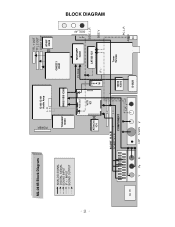
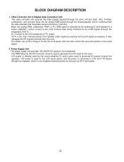
BLOCK DIAGRAM ML-041B Block Diagram ANALOG SIGNAL DIGITAL SIGNAL SOUND INPUT IF +,- SIDE_L,R SIDE V AC IN SCART R,G,B SCART V,L,R COMPONENT L,R Y Pb Pr H/P S-VHS V 14066 IC202 D-SUB Tuner TU1000 PC L,R AUDIO PC INPUT SOUND OUTPUT POWER SIDE_AV IC100 IC101 Audio Amp L, R TC90A65F IC500 SM5301BS IC800 GM2221 IC901 TTL 1 OUT TTL 2 OUT LVDS1 OUT AT49F IC905 AT24C16 IC4 RGB OUT VCTI IC1 PC RGB M52758FP IC851 Z1000 S A W LA7222 IC2 IF+,-
BLOCK DIAGRAM ML-041B Block Diagram ANALOG SIGNAL DIGITAL SIGNAL SOUND INPUT IF +,- SIDE_L,R SIDE V AC IN SCART R,G,B SCART V,L,R COMPONENT L,R Y Pb Pr H/P S-VHS V 14066 IC202 D-SUB Tuner TU1000 PC L,R AUDIO PC INPUT SOUND OUTPUT POWER SIDE_AV IC100 IC101 Audio Amp L, R TC90A65F IC500 SM5301BS IC800 GM2221 IC901 TTL 1 OUT TTL 2 OUT LVDS1 OUT AT49F IC905 AT24C16 IC4 RGB OUT VCTI IC1 PC RGB M52758FP IC851 Z1000 S A W LA7222 IC2 IF+,-
Service Manual
Page 22
... output. Either the analog RGB, component YPbPr or PC RGB signal is selected by the sound amplifier IC and is also used to generate 5V power through the regulator. 12V power is used for the LCD panel power, and 5V power is directly used for the tuner. 15V power is converted to 3.3V and 1.8V power through the tuner, AV port (AV1, AV2, S-Video, component), and converts them into the LCD panel, and can control timing to...
... output. Either the analog RGB, component YPbPr or PC RGB signal is selected by the sound amplifier IC and is also used to generate 5V power through the regulator. 12V power is used for the LCD panel power, and 5V power is directly used for the tuner. 15V power is converted to 3.3V and 1.8V power through the tuner, AV port (AV1, AV2, S-Video, component), and converts them into the LCD panel, and can control timing to...
Service Manual
Page 25
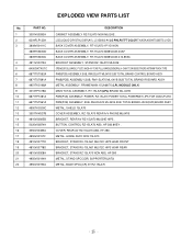
LCD(LIQUID CRYSTAL DISPLAY), LC150X02-A4 LG PHILPS TFT COLOR TN,XGA,450NITS,8BITS LVDS BACK COVER ASSEMBLY, RT-15LA70 1P/1D NON BACK COVER ASSEMBLY, RT-15LA70 3808V0433 40AF BACK COVER ASSEMBLY, RT-15LA70 3808V0433 412-855A BRACKET ASSEMBLY, STAND RZ-15LA70 ML024E . METAL, STAND SPCC(CR) SUPPORTER(LA70) METAL, BASE SPCC(CR) 3T RZ-15LA70 SPEAKER,FULLRANGE, F1527C-6428-4 K-TONE FULL-RANGE(GENERAL) 4 OHM...
LCD(LIQUID CRYSTAL DISPLAY), LC150X02-A4 LG PHILPS TFT COLOR TN,XGA,450NITS,8BITS LVDS BACK COVER ASSEMBLY, RT-15LA70 1P/1D NON BACK COVER ASSEMBLY, RT-15LA70 3808V0433 40AF BACK COVER ASSEMBLY, RT-15LA70 3808V0433 412-855A BRACKET ASSEMBLY, STAND RZ-15LA70 ML024E . METAL, STAND SPCC(CR) SUPPORTER(LA70) METAL, BASE SPCC(CR) 3T RZ-15LA70 SPEAKER,FULLRANGE, F1527C-6428-4 K-TONE FULL-RANGE(GENERAL) 4 OHM...


