
User Guide
Page 3
... a metal chopstick) into the wall input terminal. - The power supply cord is easily accessible after plugging into one end of thunder and lightning, never touch the power cord and signal cable because it is connected to use the product for exclusive use . - Caution Do not unplug the power cord while the product is the power cord and this breaking device must be located at a location where it can be electrocuted...
... a metal chopstick) into the wall input terminal. - The power supply cord is easily accessible after plugging into one end of thunder and lightning, never touch the power cord and signal cable because it is connected to use the product for exclusive use . - Caution Do not unplug the power cord while the product is the power cord and this breaking device must be located at a location where it can be electrocuted...
User Guide
Page 4
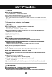
...box. Contact with a product for a long time. Caution Do not put or store inflammable substances near the product. - The water can sink into the product, which can cause electric shock or fire. Take a rest from time to time to prevent scratching. Set the appropriate resolution... and natural position when working with the service center for check, calibration or repair. Your vision can occur. - Use authorized detergent only when cleaning the product. (Do not use benzene, thinner or alcohol.) - Disposal of this product with a product to the User's Guide. - Fire or electric...
...box. Contact with a product for a long time. Caution Do not put or store inflammable substances near the product. - The water can sink into the product, which can cause electric shock or fire. Take a rest from time to time to prevent scratching. Set the appropriate resolution... and natural position when working with the service center for check, calibration or repair. Your vision can occur. - Use authorized detergent only when cleaning the product. (Do not use benzene, thinner or alcohol.) - Disposal of this product with a product to the User's Guide. - Fire or electric...
User Guide
Page 5
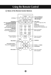
...; Power On/Off Button • Input Select Button (See next page) • ARC button To select the image size of time. Press this button repetitively to set the intended screen. Automatically adjusts the image. Press this button repetitively to select an appropriate time duration • PSM Button - Using the Remote Control Name of the Remote Control Buttons • AV Button • Sleep Button When watching AV/S-Video/RGB/HDMI /Component1/ Component2 The product will be automatically turned...
...; Power On/Off Button • Input Select Button (See next page) • ARC button To select the image size of time. Press this button repetitively to set the intended screen. Automatically adjusts the image. Press this button repetitively to select an appropriate time duration • PSM Button - Using the Remote Control Name of the Remote Control Buttons • AV Button • Sleep Button When watching AV/S-Video/RGB/HDMI /Component1/ Component2 The product will be automatically turned...
User Guide
Page 7
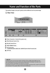
... PC sound card. Rear View REMOTE CONTROL IN RS-232C (CONTROL& SERVICE) OUT HDMI/DVI IN IN RGB IN RGB OUT AUDIO (RGB/DVI) COMPONENT IN VIDEO Y P B P R L-AUDIO-R 1 2 VIDEO AV IN L-AUDIO-R AV OUT S-VIDEO REMOTE CONTROL IN RS-232C (CONTROL& SERVICE) OUT HDMI/DVI IN IN RGB IN RGB OUT AUDIO (RGB/DVI) COMPONENT IN VIDEO Y P B P R L-AUDIO-R 1 2 VIDEO AV IN L-AUDIO-R AV OUT S-VIDEO Power Connector : Connect the power cord Wired Remote Control Port RS-232C Serial Ports RGB, HDMI/DVI Ports PC Sound Jack : Connect the audio cable to the speaker...
... PC sound card. Rear View REMOTE CONTROL IN RS-232C (CONTROL& SERVICE) OUT HDMI/DVI IN IN RGB IN RGB OUT AUDIO (RGB/DVI) COMPONENT IN VIDEO Y P B P R L-AUDIO-R 1 2 VIDEO AV IN L-AUDIO-R AV OUT S-VIDEO REMOTE CONTROL IN RS-232C (CONTROL& SERVICE) OUT HDMI/DVI IN IN RGB IN RGB OUT AUDIO (RGB/DVI) COMPONENT IN VIDEO Y P B P R L-AUDIO-R 1 2 VIDEO AV IN L-AUDIO-R AV OUT S-VIDEO Power Connector : Connect the power cord Wired Remote Control Port RS-232C Serial Ports RGB, HDMI/DVI Ports PC Sound Jack : Connect the audio cable to the speaker...
User Guide
Page 8
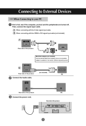
... incompatible adapter is available in the market. (Different signaling system) HDMI/DVI IN B (not included) Rear side of the product. A RGB IN Rear side of the product. REMOTE CONTROL IN RS-232C (CONTROL& SERVICE) OUT IN HDMI/DVI IN RGB IN RGB OUT AUDIO (RGB/DVI) COMPONENT IN VIDEO Y P B P R L-AUDIO-R 1 2 VIDEO AV IN L-AUDIO-R AV OUT S-VIDEO 7 Connect the power cord. B When connecting with the D-Sub signal input cable. Connecting to External Devices When Connecting to DVI signal input cable...
... incompatible adapter is available in the market. (Different signaling system) HDMI/DVI IN B (not included) Rear side of the product. A RGB IN Rear side of the product. REMOTE CONTROL IN RS-232C (CONTROL& SERVICE) OUT IN HDMI/DVI IN RGB IN RGB OUT AUDIO (RGB/DVI) COMPONENT IN VIDEO Y P B P R L-AUDIO-R 1 2 VIDEO AV IN L-AUDIO-R AV OUT S-VIDEO 7 Connect the power cord. B When connecting with the D-Sub signal input cable. Connecting to External Devices When Connecting to DVI signal input cable...
User Guide
Page 9
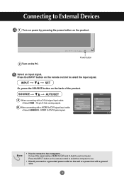
... the wall or a power bar with a D-Sub signal input cable. • Select RGB : 15-pin D-Sub analog signal. Connect the signal cables (HDMI to DVI and D-Sub) to External Devices 1 Turn on power by pressing the power button on the product. 2 Turn on the remote control to select the computer to use. • Directly connect to select the input signal. Connecting to each computer. SOURCE AUTO/SET Input Input A When connecting with a ground wire. 8 Note • How to connect to DVI Digital signal...
... the wall or a power bar with a D-Sub signal input cable. • Select RGB : 15-pin D-Sub analog signal. Connect the signal cables (HDMI to DVI and D-Sub) to External Devices 1 Turn on power by pressing the power button on the product. 2 Turn on the remote control to select the computer to use. • Directly connect to select the input signal. Connecting to each computer. SOURCE AUTO/SET Input Input A When connecting with a ground wire. 8 Note • How to connect to DVI Digital signal...

User Guide
Page 11
...) Audio Cable (not included) S-Video Cable (not included) VCR/DVD Receiver VCR/DVD Receiver Select an input signal. INPUT SET Input Or, press the SOURCE button on the remote control to External Devices When watching VCR / DVD Connect the video cable as shown in the below figure and then connect the power cord (See page 7). Note • When the BNC cable is connected simultaneously with an S-Video cable. • Select AV. A When connecting with a BNC cable. • Connect the input terminal with a proper color...
...) Audio Cable (not included) S-Video Cable (not included) VCR/DVD Receiver VCR/DVD Receiver Select an input signal. INPUT SET Input Or, press the SOURCE button on the remote control to External Devices When watching VCR / DVD Connect the video cable as shown in the below figure and then connect the power cord (See page 7). Note • When the BNC cable is connected simultaneously with an S-Video cable. • Select AV. A When connecting with a BNC cable. • Connect the input terminal with a proper color...
User Guide
Page 12
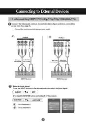
...SOURCE button on the remote control to External Devices When watching HDTV/DVD(480p/576p/720p/1080i/480i/576i) Connect the video/audio cable as shown in the below figure and then, connect the power cord (See page 7). • Connect the input terminal with a proper color match. A Product COMPONENT IN VIDEO Y P B P R L-AUDIO-R 1 2 B Product COMPONENT IN VIDEO Y P B P R L-AUDIO-R 1 2 BNC Cable Audio Cable (not included) (not included) BNC Cable Audio Cable (not included) (not included) HDTV Receiver HDTV Receiver Select an input signal. SOURCE AUTO/SET Input...
...SOURCE button on the remote control to External Devices When watching HDTV/DVD(480p/576p/720p/1080i/480i/576i) Connect the video/audio cable as shown in the below figure and then, connect the power cord (See page 7). • Connect the input terminal with a proper color match. A Product COMPONENT IN VIDEO Y P B P R L-AUDIO-R 1 2 B Product COMPONENT IN VIDEO Y P B P R L-AUDIO-R 1 2 BNC Cable Audio Cable (not included) (not included) BNC Cable Audio Cable (not included) (not included) HDTV Receiver HDTV Receiver Select an input signal. SOURCE AUTO/SET Input...
User Guide
Page 13
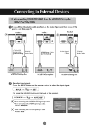
...) Connect the video/audio cable as shown in the below figure and then connect the power cord (See page 7). Press the INPUT button on the back of the product. When connecting with a HDMI signal input cable. • Select HDMI/DVI B When connecting with a HDMI to select the input signal. Connecting to DVI Signal Cable RCA-PC (not included) Audio Cable HDMI Signal Cable (not included) D-Sub Signal Cable RCA-PC Audio Cable VCR/DVD/Set-top Box VCR/DVD/Set-top Box VCR/DVD/Set-top Box Select an input signal. SOURCE AUTO/SET Input Input A When connecting...
...) Connect the video/audio cable as shown in the below figure and then connect the power cord (See page 7). Press the INPUT button on the back of the product. When connecting with a HDMI signal input cable. • Select HDMI/DVI B When connecting with a HDMI to select the input signal. Connecting to DVI Signal Cable RCA-PC (not included) Audio Cable HDMI Signal Cable (not included) D-Sub Signal Cable RCA-PC Audio Cable VCR/DVD/Set-top Box VCR/DVD/Set-top Box VCR/DVD/Set-top Box Select an input signal. SOURCE AUTO/SET Input Input A When connecting...
User Guide
Page 16
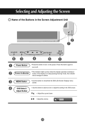
... Screen Display) menu screen. Power Indicator • This Indicator lights up and down. • Adjust the volume. 15 MENU Button • Use this button again to turn on mode). If the display is in the Screen Adjustment Unit SOURCE SOURCE AUTO/SET ON/OFF AUTO/SET ON/OFF Power Button • Press this button to turn it off. Selecting and Adjusting the Screen Name of the Buttons in sleep (Energy Saving) mode, this indicator colour changes to amber. OSD Select / Adjust Button • Use this button to...
... Screen Display) menu screen. Power Indicator • This Indicator lights up and down. • Adjust the volume. 15 MENU Button • Use this button again to turn on mode). If the display is in the Screen Adjustment Unit SOURCE SOURCE AUTO/SET ON/OFF AUTO/SET ON/OFF Power Button • Press this button to turn it off. Selecting and Adjusting the Screen Name of the Buttons in sleep (Energy Saving) mode, this indicator colour changes to amber. OSD Select / Adjust Button • Use this button to...

User Guide
Page 17
Selecting and Adjusting the Screen Name of the Buttons in the Screen Adjustment Unit AUTO/SET Button [For PC Analog signal] Auto in progress For opimal display change resolution to 1360 X 768 [When XGA Mode is active and 1360 X768 is selected] SOURCE Button SOURCE AUTO/SET • Select the input signal Input AV Component 1 Component 2 RGB HDMI/DVI Composite Video, Separate Video HDTV, DVD HDTV, DVD 15-pin D-Sub analog signal Digital signal IR Receiver • The unit that receives the signal from the remote control. 16
Selecting and Adjusting the Screen Name of the Buttons in the Screen Adjustment Unit AUTO/SET Button [For PC Analog signal] Auto in progress For opimal display change resolution to 1360 X 768 [When XGA Mode is active and 1360 X768 is selected] SOURCE Button SOURCE AUTO/SET • Select the input signal Input AV Component 1 Component 2 RGB HDMI/DVI Composite Video, Separate Video HDTV, DVD HDTV, DVD 15-pin D-Sub analog signal Digital signal IR Receiver • The unit that receives the signal from the remote control. 16
User Guide
Page 19
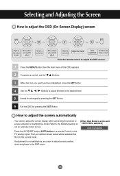
... the adjustment menu screen. • Use the remote control to adjust the OSD screen. 1 Press the MENU Button, then the main menu of the OSD appears. 2 To access a control, use the Buttons. 3 When the icon you need to adjust the screen display when connecting the product to [When XGA Mode is active and a new computer or changing the mode. How to adjust the screen automatically You need to the desired level. 5 Accept the changes by pressing the SET Button...
... the adjustment menu screen. • Use the remote control to adjust the OSD screen. 1 Press the MENU Button, then the main menu of the OSD appears. 2 To access a control, use the Buttons. 3 When the icon you need to adjust the screen display when connecting the product to [When XGA Mode is active and a new computer or changing the mode. How to adjust the screen automatically You need to the desired level. 5 Accept the changes by pressing the SET Button...

User Guide
Page 22
... internal speakers of the set the Surround MAX on the video type that you're currently watching. To use the user-defined audio settings. If you set . Balance Use this function to use this option to balance sound from the left and right speakers. Selecting and Adjusting the Screen Adjusting the audio function SSM AVL Balance 0 Speaker SSM SSM AVL Balance 0 Speaker Surround MAX Flat Music Movie Sports User The best sound tone...
... internal speakers of the set the Surround MAX on the video type that you're currently watching. To use the user-defined audio settings. If you set . Balance Use this function to use this option to balance sound from the left and right speakers. Selecting and Adjusting the Screen Adjusting the audio function SSM AVL Balance 0 Speaker SSM SSM AVL Balance 0 Speaker Surround MAX Flat Music Movie Sports User The best sound tone...
User Guide
Page 24
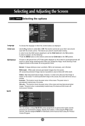
... you change the image. The monitor can only be impossible to remain on the remote control and set the Child lock tab to individually control each product when several products are displayed. Avoid allowing a fixed image to clear entirely with the remote control. Language Child lock ISM Method Set ID Tile Mode 1 Power Indicator Logo light Demo You can prevent unauthorized viewing. Specify the number (1~99) using the Product Control Program. 23...
... you change the image. The monitor can only be impossible to remain on the remote control and set the Child lock tab to individually control each product when several products are displayed. Avoid allowing a fixed image to clear entirely with the remote control. Language Child lock ISM Method Set ID Tile Mode 1 Power Indicator Logo light Demo You can prevent unauthorized viewing. Specify the number (1~99) using the Product Control Program. 23...

User Guide
Page 25
... that can be connected to RS-232C or RGB Out Tile mode • Tile Mode Language Child lock ISM Method Set ID Tile Mode Power Indicator Logo light Demo Tile Mode Natural Tile ID H-Size V-Size H-Position V-Position Reset Off Off 0 0 0 To set location. * Only after pressing the SET button the adjustments made to the settings will be displayed with several products to enlarge the screen and also used with various other...
... that can be connected to RS-232C or RGB Out Tile mode • Tile Mode Language Child lock ISM Method Set ID Tile Mode Power Indicator Logo light Demo Tile Mode Natural Tile ID H-Size V-Size H-Position V-Position Reset Off Off 0 0 0 To set location. * Only after pressing the SET button the adjustments made to the settings will be displayed with several products to enlarge the screen and also used with various other...

User Guide
Page 27
... and Adjusting the Screen Selecting the options Language Child lock ISM Method Set ID Tile Mode Power Indicator Logo light Demo Tile Mode Natural Tile ID H-Size V-Size H-Position V-Position Reset Off Off 0 0 0 To set • Natural The image is not available in RGB PC/ HDMI/DVI PC mode.) 26 Adjust the vertical size of the screen taking into account the size of the bezel. Demo Use it will automatically be turned...
... and Adjusting the Screen Selecting the options Language Child lock ISM Method Set ID Tile Mode Power Indicator Logo light Demo Tile Mode Natural Tile ID H-Size V-Size H-Position V-Position Reset Off Off 0 0 0 To set • Natural The image is not available in RGB PC/ HDMI/DVI PC mode.) 26 Adjust the vertical size of the screen taking into account the size of the bezel. Demo Use it will automatically be turned...
User Guide
Page 30
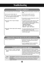
... if the plug&play function is kHz. 29 G Is the power indicator light on? • See if the power switch is turned on , power indicator is not connected. L • The control locking function prevents unintentional OSD setting change due to the video card user manual. 'Controls Locked' message appears. G The 'Controls Locked' message appears when pressing the Menu button. Check the signal cable. • Press the 'INPUT' menu in the remote Control to the outlet. Adjust the frequency range...
... if the plug&play function is kHz. 29 G Is the power indicator light on? • See if the power switch is turned on , power indicator is not connected. L • The control locking function prevents unintentional OSD setting change due to the video card user manual. 'Controls Locked' message appears. G The 'Controls Locked' message appears when pressing the Menu button. Check the signal cable. • Press the 'INPUT' menu in the remote Control to the outlet. Adjust the frequency range...
User Guide
Page 31
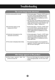
... quickly. Setting menu. Troubleshooting The screen image looks abnormal. If adjustment is not connected to the recommended resolution in the remote control to automatically select the optimal screen status that matches with the source input signal. G Is the screen position wrong? • D-Sub analog signal - G Horizontal noise appears or the characters look blurred. • D-Sub analog signal - Connect the signal cable that fits into the current mode. Use the screen-saver function. 30 Press the "AUTO" button...
... quickly. Setting menu. Troubleshooting The screen image looks abnormal. If adjustment is not connected to the recommended resolution in the remote control to automatically select the optimal screen status that matches with the source input signal. G Is the screen position wrong? • D-Sub analog signal - G Horizontal noise appears or the characters look blurred. • D-Sub analog signal - Connect the signal cable that fits into the current mode. Use the screen-saver function. 30 Press the "AUTO" button...

User Guide
Page 32
... (red, green, white or black color) may appear on the screen, which can be attributable to more than 24 bits (true color) Select Control Panel - G No sound? • See if the audio cable is connected properly. • Adjust the volume. • See if the sound is unstable or mono- • Check the connection status of the LCD panel. Or, re-insert the PC video card. G Screen has poor color resolution (16 colors). • Set the number...
... (red, green, white or black color) may appear on the screen, which can be attributable to more than 24 bits (true color) Select Control Panel - G No sound? • See if the audio cable is connected properly. • Adjust the volume. • See if the sound is unstable or mono- • Check the connection status of the LCD panel. Or, re-insert the PC video card. G Screen has poor color resolution (16 colors). • Set the number...
User Guide
Page 33
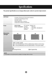
... this document is subject to change without notice. 32 LCD Panel Power 47 inches (119.28 cm) TFT (Thin Film Transistor) LCD (Liquid Crystal Display) Panel Anti-Glare coating Visible diagonal size: 119.28 cm 0.76125 mm X 0.76125 mm (Pixel Pitch) Rated Voltage Power Consumption AC 100-240V~ 50/60Hz 3.0A On Mode : 300W Typ. Specifications The product specifications can change without prior notice for...
... this document is subject to change without notice. 32 LCD Panel Power 47 inches (119.28 cm) TFT (Thin Film Transistor) LCD (Liquid Crystal Display) Panel Anti-Glare coating Visible diagonal size: 119.28 cm 0.76125 mm X 0.76125 mm (Pixel Pitch) Rated Voltage Power Consumption AC 100-240V~ 50/60Hz 3.0A On Mode : 300W Typ. Specifications The product specifications can change without prior notice for...


