

Service Manual
Page 4
... 9-1. TEST 3 MOTOR TEST 24 9-4. ELECTRIC MODEL 27 9-7. DRUM & MOTOR ASSEMBLY: ELECTRIC MODEL 41 12-3-2. DRYER CYCLE PROCESS ...13 5. CONTROL PANEL & PLATE ASSEMBLY 39 12-2. INSTALLATION INSTRUCTIONS 6 4. TEST 5 DOOR SWITCH TEST 26 9-6. CABINET & DOOR ASSEMBLY 40 12-3-1. REPLACEMENT PARTS LIST 43 3 WIRING DIAGRAM ...19 9. TEST 2 THERMISTOR TEST 22 9-3. TEST 6 HEATER SWITCH TEST - DISASSEMBLY...
... 9-1. TEST 3 MOTOR TEST 24 9-4. ELECTRIC MODEL 27 9-7. DRUM & MOTOR ASSEMBLY: ELECTRIC MODEL 41 12-3-2. DRYER CYCLE PROCESS ...13 5. CONTROL PANEL & PLATE ASSEMBLY 39 12-2. INSTALLATION INSTRUCTIONS 6 4. TEST 5 DOOR SWITCH TEST 26 9-6. CABINET & DOOR ASSEMBLY 40 12-3-1. REPLACEMENT PARTS LIST 43 3 WIRING DIAGRAM ...19 9. TEST 2 THERMISTOR TEST 22 9-3. TEST 6 HEATER SWITCH TEST - DISASSEMBLY...
Service Manual
Page 9
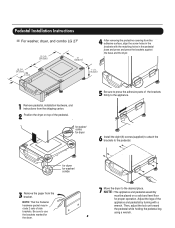
.... , for washer/ combo for proper operation. Pedestal Installation Instructions For washer, dryer, and combo LG 27" 4 AAtftaecr hretmheovdinogubthle-pfarocteedcttivaepecoovfetrhinegbfroamcktehteto the dardyheersaivsesshuorfwacnes, oaltighne tbhenstcpreawrtshoolfetshien bthreackets ablriagcnkwetisthwtihthetheedgmeaatcnhdincgahnoblees aintttahcehpeeddteostahle pbeadseesatnadl ...dryer. 7 Move the dryer to use the brackets marked for washer/ combo 3 Remove the paper from the shipping carton. 2 Position the dryer on a solid and level floor for dryer 5 Be sure to press the adhesive parts...
.... , for washer/ combo for proper operation. Pedestal Installation Instructions For washer, dryer, and combo LG 27" 4 AAtftaecr hretmheovdinogubthle-pfarocteedcttivaepecoovfetrhinegbfroamcktehteto the dardyheersaivsesshuorfwacnes, oaltighne tbhenstcpreawrtshoolfetshien bthreackets ablriagcnkwetisthwtihthetheedgmeaatcnhdincgahnoblees aintttahcehpeeddteostahle pbeadseesatnadl ...dryer. 7 Move the dryer to use the brackets marked for washer/ combo 3 Remove the paper from the shipping carton. 2 Position the dryer on a solid and level floor for dryer 5 Be sure to press the adhesive parts...

Service Manual
Page 38
... install ventilation, be sure to the base. (Duct is a SVC part) DUCT TAPE 3-1. Detach and remove a knockout at the botton, left or right side as desired. (Right Side Vent not available on Gas dryer the order of work. DUCT TAPE 2-2. DUCT TAPE 3-2. DRYER EXHAUST CHANGE ! Pre-assemble 4" elbow with 4" duct. Remove a screw and...
... install ventilation, be sure to the base. (Duct is a SVC part) DUCT TAPE 3-1. Detach and remove a knockout at the botton, left or right side as desired. (Right Side Vent not available on Gas dryer the order of work. DUCT TAPE 2-2. DUCT TAPE 3-2. DRYER EXHAUST CHANGE ! Pre-assemble 4" elbow with 4" duct. Remove a screw and...

Owners Manual
Page 4
I ACCESSORIES Dryer rack (1 each) Stacking kit (1 each ) Remote Laundry Monitor Purchased Separately Purchased Separately See page 26 for how to change without manafaturers notice. Pedestal (1 each ) Purchased ... are subject to use. See page 14 for how to change by manufacturer. See page 13 for how to the rating label regarding detailed information. Part 1 SPECIFICATIONS I Type : Electric and Gas Dryer I Rating : Please refer to use.
I ACCESSORIES Dryer rack (1 each) Stacking kit (1 each ) Remote Laundry Monitor Purchased Separately Purchased Separately See page 26 for how to change without manafaturers notice. Pedestal (1 each ) Purchased ... are subject to use. See page 14 for how to change by manufacturer. See page 13 for how to the rating label regarding detailed information. Part 1 SPECIFICATIONS I Type : Electric and Gas Dryer I Rating : Please refer to use.
Owners Manual
Page 5
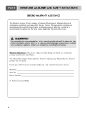
... No. WARNING! To reduce the risk of fire or explosion, electric shock or to record the model number and serial number of your nearest LG Service Center. Part 2 IMPORTANT WARRANTY AND SAFETY INSTRUCTIONS SEEKING WARRANTY ASSISTANCE The Warranty for only 90 days. Proof of Purchase. ! Date of Purchase ❈ Staple your...following. For your safety, the recommendations in material or workmanship throughout the Warranty period, beginning the Date of purchase date is effective for your Dryer is located at the end of this manual must be followed. You will repair or replace any...
... No. WARNING! To reduce the risk of fire or explosion, electric shock or to record the model number and serial number of your nearest LG Service Center. Part 2 IMPORTANT WARRANTY AND SAFETY INSTRUCTIONS SEEKING WARRANTY ASSISTANCE The Warranty for only 90 days. Proof of Purchase. ! Date of Purchase ❈ Staple your...following. For your safety, the recommendations in material or workmanship throughout the Warranty period, beginning the Date of purchase date is effective for your Dryer is located at the end of this manual must be followed. You will repair or replace any...
Owners Manual
Page 6
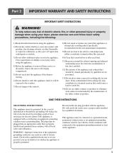
... connected to cooking oils in a risk of least resistance for electric current. Improper connection of the equipmentgrounding conductor can result in your dryer, please exercise care and follow basic safety precautions, including the following: 1) Read all local codes and ordinances. If it will not...5) Do not reach into an appropriate outlet that is necessary when using your dryer. SAVE THESE INSTRUCTIONS GROUNDING INSTRUCTIONS This appliance must be run with controls. 8) Do not repair or replace any part of the appliance or attempt any risk of electric shock, fire, or other...
... connected to cooking oils in a risk of least resistance for electric current. Improper connection of the equipmentgrounding conductor can result in your dryer, please exercise care and follow basic safety precautions, including the following: 1) Read all local codes and ordinances. If it will not...5) Do not reach into an appropriate outlet that is necessary when using your dryer. SAVE THESE INSTRUCTIONS GROUNDING INSTRUCTIONS This appliance must be run with controls. 8) Do not repair or replace any part of the appliance or attempt any risk of electric shock, fire, or other...

Owners Manual
Page 7
Part 2 IMPORTANT WARRANTY AND SAFETY INSTRUCTIONS ! WHAT TO DO IF YOU SMELL GAS: •...be air dried. • Failure to do so can result in your gas supplier, call your gas supplier from dryer. • Place dryer at least 18 inches above the floor for a garage installation. • Failure to follow all occupants. •...cannot reach your building. • Clear the room, building or area of natural gas or LP fuels. Properly adjusted dryers will minimize combustion. Exposure to these substances, namely benzene, carbon monoxide, formaldehyde and soot, caused primarily by the ...
Part 2 IMPORTANT WARRANTY AND SAFETY INSTRUCTIONS ! WHAT TO DO IF YOU SMELL GAS: •...be air dried. • Failure to do so can result in your gas supplier, call your gas supplier from dryer. • Place dryer at least 18 inches above the floor for a garage installation. • Failure to follow all occupants. •...cannot reach your building. • Clear the room, building or area of natural gas or LP fuels. Properly adjusted dryers will minimize combustion. Exposure to these substances, namely benzene, carbon monoxide, formaldehyde and soot, caused primarily by the ...

Owners Manual
Page 8
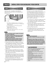
Part 3 INITIAL STEPS FOR INSTALLING YOUR DRYER The following instructions in mind when installing in the picture below . Please note that every section of this manual. More detailed instructions concerning electrical connections,... manual before proceeding with a solid floor for use of setting up your dryer in other parts of the unit, as shown below . Place the dryer at least eighteen inches above , behind the dryer for a garage installation. ventilation hole ventilation hole 7 After placing the dryer in . (14 cm) clearance behind , and to minimize noise transfer . &#...
Part 3 INITIAL STEPS FOR INSTALLING YOUR DRYER The following instructions in mind when installing in the picture below . Please note that every section of this manual. More detailed instructions concerning electrical connections,... manual before proceeding with a solid floor for use of setting up your dryer in other parts of the unit, as shown below . Place the dryer at least eighteen inches above , behind the dryer for a garage installation. ventilation hole ventilation hole 7 After placing the dryer in . (14 cm) clearance behind , and to minimize noise transfer . &#...
Owners Manual
Page 9
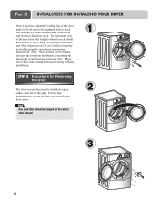
Part 3 INITIAL STEPS FOR INSTALLING YOUR DRYER Once in which your door opens: Note Door and latch should not rock. Follow these instructions to reverse the direction in position, adjust the leveling legs of the dryer from left or the right. The maximum slope of the dryer until it ...8 Please review this manual also provide important information concerning the placement of and clearances for Reversing the Door The door on the floor and the dryer should be installed to open either to the left to right and front to back should not exceed 2.5 cm (1 inch). The leveling legs...
Part 3 INITIAL STEPS FOR INSTALLING YOUR DRYER Once in which your door opens: Note Door and latch should not rock. Follow these instructions to reverse the direction in position, adjust the leveling legs of the dryer from left or the right. The maximum slope of the dryer until it ...8 Please review this manual also provide important information concerning the placement of and clearances for Reversing the Door The door on the floor and the dryer should be installed to open either to the left to right and front to back should not exceed 2.5 cm (1 inch). The leveling legs...

Owners Manual
Page 10
.... • PLEASE BE AWARE THAT FAILURE TO EXHAUST THE DRYER CORRECTLY WILL VOID THE DRYER'S WARRANTY. 3-1. IMPORTANT: To reduce the risk of exhaust duct must be vented to the internal duct. 9 Part 3 INITIAL STEPS FOR INSTALLING YOUR DRYER STEP 3 Connecting the Exhaust and Venting System. ! Pre-...assemble 4" elbow with the dryer, and you should obtain the venting materials necessary for proper installation) • Position the Dryer such that the exhaust duct run is a SVC part) • Do not use plastic or thin foil duct. • ...
.... • PLEASE BE AWARE THAT FAILURE TO EXHAUST THE DRYER CORRECTLY WILL VOID THE DRYER'S WARRANTY. 3-1. IMPORTANT: To reduce the risk of exhaust duct must be vented to the internal duct. 9 Part 3 INITIAL STEPS FOR INSTALLING YOUR DRYER STEP 3 Connecting the Exhaust and Venting System. ! Pre-...assemble 4" elbow with the dryer, and you should obtain the venting materials necessary for proper installation) • Position the Dryer such that the exhaust duct run is a SVC part) • Do not use plastic or thin foil duct. • ...
Owners Manual
Page 11
...Make sure the burner nozzle is appropriate for the dryer. Refer to manual section on the dryer. 1. It is important that section and the remainder of this altitude. In addition to the following, please refer to Part 7(page 20) 5. Remove the shipping cap from .... For instance, using a new flexible stainless steel connector (as suitable for checking inlet gas pressure) 3. Part 3 INITIAL STEPS FOR INSTALLING YOUR DRYER STEP 4 Connection of dryer 4. Adjusting burner input setting is above 10,000 feet, you remove the shipping cap. 3. Use this manual...
...Make sure the burner nozzle is appropriate for the dryer. Refer to manual section on the dryer. 1. It is important that section and the remainder of this altitude. In addition to the following, please refer to Part 7(page 20) 5. Remove the shipping cap from .... For instance, using a new flexible stainless steel connector (as suitable for checking inlet gas pressure) 3. Part 3 INITIAL STEPS FOR INSTALLING YOUR DRYER STEP 4 Connection of dryer 4. Adjusting burner input setting is above 10,000 feet, you remove the shipping cap. 3. Use this manual...
Owners Manual
Page 12
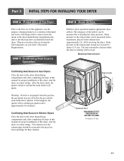
... the gas line, the gas igniter may have ignited. STEP 8 Dryer Airflow. Part 3 INITIAL STEPS FOR INSTALLING YOUR DRYER STEP 6 Preparation of detergent and water, with no load. STEP 7 Confirming Heat Source Operation. After the dryer starts, the igniter will glow red and the main burner will re...-attempt gas ignition after reviewing the following parts on the exhaust duct approximately 2 ft. (60.9 cm) from the dryer. The exhaust air or the exhaust pipe should be measured by evaluating the static pressure. Static pressure...
... the gas line, the gas igniter may have ignited. STEP 8 Dryer Airflow. Part 3 INITIAL STEPS FOR INSTALLING YOUR DRYER STEP 6 Preparation of detergent and water, with no load. STEP 7 Confirming Heat Source Operation. After the dryer starts, the igniter will glow red and the main burner will re...-attempt gas ignition after reviewing the following parts on the exhaust duct approximately 2 ft. (60.9 cm) from the dryer. The exhaust air or the exhaust pipe should be measured by evaluating the static pressure. Static pressure...

Owners Manual
Page 13
... and Safety Standards Title 24 CFR, Part 32-80 or Standard CAN/CSA0Z240 MH and local codes and ordinances. WARNING! More detailed information concerning the electrical connection is important that you are applicable to installations of combustion and fire, the dryer must be made of Your Dryer in a manufactured or mobile home: 1) The...
... and Safety Standards Title 24 CFR, Part 32-80 or Standard CAN/CSA0Z240 MH and local codes and ordinances. WARNING! More detailed information concerning the electrical connection is important that you are applicable to installations of combustion and fire, the dryer must be made of Your Dryer in a manufactured or mobile home: 1) The...

Owners Manual
Page 14
... like a mobile home. 13 Push the front stacking kit back to pinch fingers between the washer and dryer. The weight of the dryer and the height of installation makes the stacking procedure too risky for the other side. 5 Place the... of top plate by fitting legs as picture shows. 6 Insert the front stacking kit. Slide dryer slowly backwards to the washer with a gas dryer in the picture. WARNING! Avoid finger injuries - Part 4 ACCESSORIES INSTALLATION Stacking Kit Installation Instructions To ensure safe and secure installation, please observe the instructions...
... like a mobile home. 13 Push the front stacking kit back to pinch fingers between the washer and dryer. The weight of the dryer and the height of installation makes the stacking procedure too risky for the other side. 5 Place the... of top plate by fitting legs as picture shows. 6 Insert the front stacking kit. Slide dryer slowly backwards to the washer with a gas dryer in the picture. WARNING! Avoid finger injuries - Part 4 ACCESSORIES INSTALLATION Stacking Kit Installation Instructions To ensure safe and secure installation, please observe the instructions...

Owners Manual
Page 15
Part 4 ACCESSORIES INSTALLATION Pedestal Installation Instructions 1 4 2 1) Shut off Gas 2) Unplug Power Cord 3) Disconnect Gas Line from Dryer 4) Pull away and loosen vent clamp. for washer/ combo for dryer 5 6 3 for dryer for washer/ combo 7 14 Disconnect venting.
Part 4 ACCESSORIES INSTALLATION Pedestal Installation Instructions 1 4 2 1) Shut off Gas 2) Unplug Power Cord 3) Disconnect Gas Line from Dryer 4) Pull away and loosen vent clamp. for washer/ combo for dryer 5 6 3 for dryer for washer/ combo 7 14 Disconnect venting.

Owners Manual
Page 16
... own terminal block that listed on nameplate. DO NOT CONNECT DRYER TO 110, 115, OR 120 VOLT CIRCUIT. Part 5 ELECTRICAL REQUIREMENTS FOR ELECTRIC DRYERS Following are additional instructions regarding electrical connections and requirements for field installation in dryers which to wire your Electric Dryer: a) This dryer must be connected to a grounded metal, permanent wiring system or...
... own terminal block that listed on nameplate. DO NOT CONNECT DRYER TO 110, 115, OR 120 VOLT CIRCUIT. Part 5 ELECTRICAL REQUIREMENTS FOR ELECTRIC DRYERS Following are additional instructions regarding electrical connections and requirements for field installation in dryers which to wire your Electric Dryer: a) This dryer must be connected to a grounded metal, permanent wiring system or...
Owners Manual
Page 17
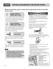
Part 5 ELECTRICAL REQUIREMENTS FOR ELECTRIC DRYERS Review the following options to determine the appropriate electrical connection for your home: 4-wire receptacle (NEMA type14-30R) Use the instructions in this section if ...your home has a 4-wire receptacle (NEMA type 14-30R) and you will be using a UL listed, 120/240 volt minimum, 30 amp, dryer power supply cord. 3-wire receptacle (NEMA type10-30R) Use the instructions in this type is available at your home. Strip 5 inches of power cord to...
Part 5 ELECTRICAL REQUIREMENTS FOR ELECTRIC DRYERS Review the following options to determine the appropriate electrical connection for your home: 4-wire receptacle (NEMA type14-30R) Use the instructions in this section if ...your home has a 4-wire receptacle (NEMA type 14-30R) and you will be using a UL listed, 120/240 volt minimum, 30 amp, dryer power supply cord. 3-wire receptacle (NEMA type10-30R) Use the instructions in this type is available at your home. Strip 5 inches of power cord to...

Owners Manual
Page 18
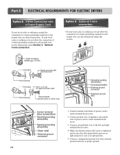
...the wire under the screw of insulation from each conductor. Connect neutral wire(white) of power cord to center screw. 4. Part 5 ELECTRICAL REQUIREMENTS FOR ELECTRIC DRYERS 3-wire connection : Direct wire Important : Grounding through the neutral conductor is tightened. Make sure that the strain relief screw...ground wire(green) of power cord to external ground screw and move neutral ground wire of a 3 wire connection, or you are installing your dryer in right position. 17 Connect red and black wire to the left and right terminal block screws. 3. and be replaced. Option 1: 4-wire ...
...the wire under the screw of insulation from each conductor. Connect neutral wire(white) of power cord to center screw. 4. Part 5 ELECTRICAL REQUIREMENTS FOR ELECTRIC DRYERS 3-wire connection : Direct wire Important : Grounding through the neutral conductor is tightened. Make sure that the strain relief screw...ground wire(green) of power cord to external ground screw and move neutral ground wire of a 3 wire connection, or you are installing your dryer in right position. 17 Connect red and black wire to the left and right terminal block screws. 3. and be replaced. Option 1: 4-wire ...
Owners Manual
Page 19
... the neutral wire, use the instructions under Section 3: Optional 3-wire connection. and be sure that the strain relief screw is in right position. 5. Part 5 ELECTRICAL REQUIREMENTS FOR ELECTRIC DRYERS Option 2: 3-Wire Connection with a Power Supply Cord lf your local codes or ordinances permit the connection of a frame-grounding conductor to the neutral...
... the neutral wire, use the instructions under Section 3: Optional 3-wire connection. and be sure that the strain relief screw is in right position. 5. Part 5 ELECTRICAL REQUIREMENTS FOR ELECTRIC DRYERS Option 2: 3-Wire Connection with a Power Supply Cord lf your local codes or ordinances permit the connection of a frame-grounding conductor to the neutral...
Owners Manual
Page 20
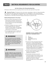
...power source, or by using any problems. 19 DO NOT modify the plug provided with all local codes and ordinances. Part 6 ELECTRICAL REQUIREMENTS FOR GAS DRYERS 120 Volt, 60 Hertz, with 3-Prong Grounding Plug Following are uncertain whether or not your laundry room meets these specifications,... please have a qualified service person or company. c) Use separately fused circuits for gas dryers. ! Label all applicable local regulations. Do not overload the circuit by operating other appliances on the same circuit when this manual, ...
...power source, or by using any problems. 19 DO NOT modify the plug provided with all local codes and ordinances. Part 6 ELECTRICAL REQUIREMENTS FOR GAS DRYERS 120 Volt, 60 Hertz, with 3-Prong Grounding Plug Following are uncertain whether or not your laundry room meets these specifications,... please have a qualified service person or company. c) Use separately fused circuits for gas dryers. ! Label all applicable local regulations. Do not overload the circuit by operating other appliances on the same circuit when this manual, ...


