

Service Manual
Page 4
... 4. WIRING DIAGRAM ...19 9. TEST 7 GAS VALVE TEST - SPECIFICATIONS ...4 2. COMPONENT TESTING INFORMATION 14 6. DIAGNOSTIC TEST ...20 9-1. DRUM & MOTOR ASSEMBLY: GAS MODEL 42 13. DRYER CYCLE PROCESS ...13 5. CONTROL LAYOUT ...18 8. TEST 4 MOISTURE SENSOR 25 9-5. GAS MODEL 28 9-8 TEST 8 SEMI-CONDUCTOR 29...INSTRUCTIONS 32 12. DRUM & MOTOR ASSEMBLY: ELECTRIC MODEL 41 12-3-2. TEST 1 120V AC ELECTRICAL SUPPLY 21 9-2. CHANGE GAS SETTING (NATURAL GAS, PROPANE GAS 30 11. EXPLODED VIEW ...39 12-1. CONTROL PANEL & PLATE ASSEMBLY 39 12-2. TEST 6 HEATER SWITCH TEST -...
... 4. WIRING DIAGRAM ...19 9. TEST 7 GAS VALVE TEST - SPECIFICATIONS ...4 2. COMPONENT TESTING INFORMATION 14 6. DIAGNOSTIC TEST ...20 9-1. DRUM & MOTOR ASSEMBLY: GAS MODEL 42 13. DRYER CYCLE PROCESS ...13 5. CONTROL LAYOUT ...18 8. TEST 4 MOISTURE SENSOR 25 9-5. GAS MODEL 28 9-8 TEST 8 SEMI-CONDUCTOR 29...INSTRUCTIONS 32 12. DRUM & MOTOR ASSEMBLY: ELECTRIC MODEL 41 12-3-2. TEST 1 120V AC ELECTRICAL SUPPLY 21 9-2. CHANGE GAS SETTING (NATURAL GAS, PROPANE GAS 30 11. EXPLODED VIEW ...39 12-1. CONTROL PANEL & PLATE ASSEMBLY 39 12-2. TEST 6 HEATER SWITCH TEST -...
Service Manual
Page 6
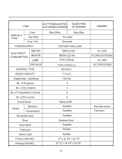
... 1/2" x 44 3/4" x 30 3/4" REMARK AC 120V AC 240V (ELECTRIC MODEL) AC 120V AC 120V (GAS MODEL) Electrode sensor Thermistor 5 of Temperature Controls No. ITEM DLE7177WM/DLE8377WM DLE8377NM DLG7188WM/DLG8388WM DLG8388NM Material & Finish Color Top Plate Door Trim POWER SUPPLY ELECTRICITY CONSUMPTION MOTOR HEATER LAMP GAS VALVE CONTROL TYPE DRUM CAPACITY Weight (lbs) - Net/Gross No.
... 1/2" x 44 3/4" x 30 3/4" REMARK AC 120V AC 240V (ELECTRIC MODEL) AC 120V AC 120V (GAS MODEL) Electrode sensor Thermistor 5 of Temperature Controls No. ITEM DLE7177WM/DLE8377WM DLE8377NM DLG7188WM/DLG8388WM DLG8388NM Material & Finish Color Top Plate Door Trim POWER SUPPLY ELECTRICITY CONSUMPTION MOTOR HEATER LAMP GAS VALVE CONTROL TYPE DRUM CAPACITY Weight (lbs) - Net/Gross No.

Service Manual
Page 13
... use with a non-corrosive leak detection fluid. 5. Make certain your laundry room. Dryer is equipped at the rear of gas in your dryer is equipped for checking inlet gas pressure) 3 Equipment Shut-Off Valve-Installed within 6' (1.8 m) of dryer 4 Black Iron Pipe Shorter than 20' (6.1 m) - Make sure you do not damage the pipe thread...
... use with a non-corrosive leak detection fluid. 5. Make certain your laundry room. Dryer is equipped at the rear of gas in your dryer is equipped for checking inlet gas pressure) 3 Equipment Shut-Off Valve-Installed within 6' (1.8 m) of dryer 4 Black Iron Pipe Shorter than 20' (6.1 m) - Make sure you do not damage the pipe thread...
Service Manual
Page 16
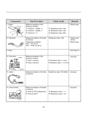
...: 2 - 3 Check result Resistance value: 10Ω Resistance value: 10Ω Resistance value: 20Ω Remark • Electric type Measure resistance of the following terminal Valve 1 terminal Valve 2 terminal • Gas type Resistance value: > 1.5 kΩ Resistance value: > 1.5~2.5 kΩ 11. Motor Test Procedure Measure resistance of terminal to terminal Resistance value: 100~800Ω •...
...: 2 - 3 Check result Resistance value: 10Ω Resistance value: 10Ω Resistance value: 20Ω Remark • Electric type Measure resistance of the following terminal Valve 1 terminal Valve 2 terminal • Gas type Resistance value: > 1.5 kΩ Resistance value: > 1.5~2.5 kΩ 11. Motor Test Procedure Measure resistance of terminal to terminal Resistance value: 100~800Ω •...
Service Manual
Page 21
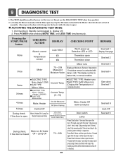
...shut off in , display off) 2. Unit must be used for Factory test /Service test. Current Temp. (5 ~ 70) ELECTRIC TYPE: Heater runs GAS TYPE: GAS Valve runs (Display the Temperature of Inside drum.) 4 times Motor, Heater 50~230 Measured "SE"(Error Display) Motor, Heater Off Semi-conductor 5 times ... 3 (by pressing start 3 times) and step 4 (by making sure the all the way to operate the heater while the door is closed. Gas valve See test 7 See test 8 Auto Off See test 6 20 Pressing the START/PAUSE button CHECKING ACTION DISPLAY CHECKING POINT REMARK None Electric control & ...
...shut off in , display off) 2. Unit must be used for Factory test /Service test. Current Temp. (5 ~ 70) ELECTRIC TYPE: Heater runs GAS TYPE: GAS Valve runs (Display the Temperature of Inside drum.) 4 times Motor, Heater 50~230 Measured "SE"(Error Display) Motor, Heater Off Semi-conductor 5 times ... 3 (by pressing start 3 times) and step 4 (by making sure the all the way to operate the heater while the door is closed. Gas valve See test 7 See test 8 Auto Off See test 6 20 Pressing the START/PAUSE button CHECKING ACTION DISPLAY CHECKING POINT REMARK None Electric control & ...

Service Manual
Page 30
..., Igniter becomes reddish) YES NO • Check Igniter & Frame detect When measuring Valve 2 voltage, Value is more than1.5 ~ 2.5kΩ? Measurement Condition With dryer power on Valve 1 and Valve 2, Valves are Off? Trouble Symptom While operating, Heating will not work. Test 7 GAS Valve test - Gas Type Caution When measuring power, be sure to wear insulated gloves, to...
..., Igniter becomes reddish) YES NO • Check Igniter & Frame detect When measuring Valve 2 voltage, Value is more than1.5 ~ 2.5kΩ? Measurement Condition With dryer power on Valve 1 and Valve 2, Valves are Off? Trouble Symptom While operating, Heating will not work. Test 7 GAS Valve test - Gas Type Caution When measuring power, be sure to wear insulated gloves, to...
Service Manual
Page 32
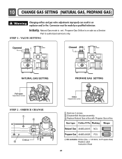
... a Service Part to authorized servicers only. Propane Gas Orifice is set. Warning Changing orifices and gas valve adjustments improperly can result in an explosion and/or fire. Replace Natural Gas orifice with Propane Gas orifice. 10 CHANGE GAS SETTING (NATURAL GAS, PROPANE GAS) ! Gas type Orifice P/No Marking Shape Natural Gas 4948EL4001B NCU Propane Gas 4948EL4002B PCU Kit contents: Orifice (Dia...
... a Service Part to authorized servicers only. Propane Gas Orifice is set. Warning Changing orifices and gas valve adjustments improperly can result in an explosion and/or fire. Replace Natural Gas orifice with Propane Gas orifice. 10 CHANGE GAS SETTING (NATURAL GAS, PROPANE GAS) ! Gas type Orifice P/No Marking Shape Natural Gas 4948EL4001B NCU Propane Gas 4948EL4002B PCU Kit contents: Orifice (Dia...
Service Manual
Page 33
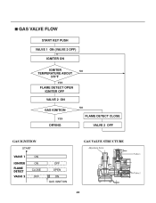
GAS VALVE FLOW START KEY PUSH VALVE 1 ON (VALVE 2 OFF) IGNITER ON IGNITER NO TEMPERATURE ABOUT 370°F YES FLAME DETECT OPEN IGNITER OFF VALVE 2 ON GAS IGNITION YES DRYING NO FLAME DETECT CLOSE VALVE 2 OFF GAS IGNITION START VALVE 1 IGNITER FLAME DETECT VALVE 2 ON ON CLOSE OFF OFF OPEN ON GAS IGNITION GAS VALVE STRUCTURE Adjustment Screw 32
GAS VALVE FLOW START KEY PUSH VALVE 1 ON (VALVE 2 OFF) IGNITER ON IGNITER NO TEMPERATURE ABOUT 370°F YES FLAME DETECT OPEN IGNITER OFF VALVE 2 ON GAS IGNITION YES DRYING NO FLAME DETECT CLOSE VALVE 2 OFF GAS IGNITION START VALVE 1 IGNITER FLAME DETECT VALVE 2 ON ON CLOSE OFF OFF OPEN ON GAS IGNITION GAS VALVE STRUCTURE Adjustment Screw 32
Owners Manual
Page 11
...should be connected to green ground connector. • Securely tighten all electrical connections • See installation instructions for Natural Gas with a non-corrosive leak detection fluid. More detailed information concerning the electrical connection is appropriate for manufactured (mobile) home...with LPG nozzle will result in the manual section entitled Electrical Requirements for checking inlet gas pressure) 3. Refer to 10,000 feet. Electrical Plug Connections. 4. Equipment Shut-Off Valve- Connect the dryer to center terminal. • Ground wire(green or bare wire...
...should be connected to green ground connector. • Securely tighten all electrical connections • See installation instructions for Natural Gas with a non-corrosive leak detection fluid. More detailed information concerning the electrical connection is appropriate for manufactured (mobile) home...with LPG nozzle will result in the manual section entitled Electrical Requirements for checking inlet gas pressure) 3. Refer to 10,000 feet. Electrical Plug Connections. 4. Equipment Shut-Off Valve- Connect the dryer to center terminal. • Ground wire(green or bare wire...

Owners Manual
Page 21
... kPa). 4. Do not attempt to connect Dryer to prevent gas valve contamination. A 1/8 in . If acceptable under local codes and ordinances and when acceptable to do so can result in LP gas. 6. To reduce the danger of gas leaks, explosion, and fire, please follow and observe the following...where lengths are important instructions and information concerning the requirements for the gas supply and service for gas dryers. ! Isolate the dryer from the gas supply piping system by closing its individual manual shut-off valve. • Securely tighten all local codes and ordinances. DO NOT...
... kPa). 4. Do not attempt to connect Dryer to prevent gas valve contamination. A 1/8 in . If acceptable under local codes and ordinances and when acceptable to do so can result in LP gas. 6. To reduce the danger of gas leaks, explosion, and fire, please follow and observe the following...where lengths are important instructions and information concerning the requirements for the gas supply and service for gas dryers. ! Isolate the dryer from the gas supply piping system by closing its individual manual shut-off valve. • Securely tighten all local codes and ordinances. DO NOT...


