
Owners Manual
Page 3
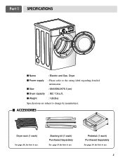
I Size : 68.6X98.3X76.1(cm) I Weight : 126(Ibs) Specifications are subject to change by manufacturer. I Dryer capacity : IEC 7.3cu.ft. I Power supply : Please refer to the rating label regarding detailed information. Pedestal (1 each ) See page 26 for how to use. Stacking kit (1 each) Purchased Separately See page 13 for how to use. Part 1 SPECIFICATIONS I Name : Electric and Gas Dryer I ACCESSORIES Dryer rack (1 each ) Purchased Separately See page 14 for how to use. 3
I Size : 68.6X98.3X76.1(cm) I Weight : 126(Ibs) Specifications are subject to change by manufacturer. I Dryer capacity : IEC 7.3cu.ft. I Power supply : Please refer to the rating label regarding detailed information. Pedestal (1 each ) See page 26 for how to use. Stacking kit (1 each) Purchased Separately See page 13 for how to use. Part 1 SPECIFICATIONS I Name : Electric and Gas Dryer I ACCESSORIES Dryer rack (1 each ) Purchased Separately See page 14 for how to use. 3
Owners Manual
Page 4
...workmanship. ! You will repair or replace any of its mechanical or electrical parts if they are located on the Model and Serial Number Plate located on the front of this manual, LG will need the complete model and serial numbers when requesting information. We ... by contacting your receipt hear. 4 Date of Purchase ❈ Staple your nearest LG Service Center and, for warranty period from the date of your appliance, follow basic precautions, including the following. Part 2 IMPORTANT WARRANTY AND SAFETY INSTRUCTIONS SEEKING WARRANTY ASSISTANCE Warranty Service. The warranty for ...
...workmanship. ! You will repair or replace any of its mechanical or electrical parts if they are located on the Model and Serial Number Plate located on the front of this manual, LG will need the complete model and serial numbers when requesting information. We ... by contacting your receipt hear. 4 Date of Purchase ❈ Staple your nearest LG Service Center and, for warranty period from the date of your appliance, follow basic precautions, including the following. Part 2 IMPORTANT WARRANTY AND SAFETY INSTRUCTIONS SEEKING WARRANTY ASSISTANCE Warranty Service. The warranty for ...
Owners Manual
Page 5
...in accordance with the circuit conductors and connected to eliminate static unless recommended by providing a path of electric shock. This appliance is properly grounded. Part 2 IMPORTANT WARRANTY AND SAFETY INSTRUCTIONS IMPORTANT SAFETY INSTRUCTIONS ! WARNING! SAVE THESE INSTRUCTIONS GROUNDING INSTRUCTIONS This appliance must be plugged into an appropriate outlet... from service or discarded, remove the door to the weather. 7) Do not tamper with controls. 8) Do not repair or replace any part of the appliance or attempt any risk of the fabric softner or product.
...in accordance with the circuit conductors and connected to eliminate static unless recommended by providing a path of electric shock. This appliance is properly grounded. Part 2 IMPORTANT WARRANTY AND SAFETY INSTRUCTIONS IMPORTANT SAFETY INSTRUCTIONS ! WARNING! SAVE THESE INSTRUCTIONS GROUNDING INSTRUCTIONS This appliance must be plugged into an appropriate outlet... from service or discarded, remove the door to the weather. 7) Do not tamper with controls. 8) Do not repair or replace any part of the appliance or attempt any risk of the fabric softner or product.
Owners Manual
Page 6
Part 2 IMPORTANT WARRANTY AND SAFETY INSTRUCTIONS ! Follow the gas supplier's instructions carefully. • If you cannot reach your gas supplier, including the following: • Do not ...
Part 2 IMPORTANT WARRANTY AND SAFETY INSTRUCTIONS ! Follow the gas supplier's instructions carefully. • If you cannot reach your gas supplier, including the following: • Do not ...
Owners Manual
Page 7
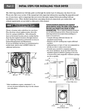
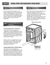
... are installing your dryer. STEP 1 Positioning the Dryer. If you review this entire manual before proceeding with elbow. ventilation hole 7 Part 3 INITIAL STEPS FOR INSTALLING YOUR DRYER The following instructions will help guide you install it is recommended an all sides in . (...cm) Certain minimum clearance are provided at least eighteen inches above ,behind the dryer for the exhaust vent with any closer of other parts of the dryer in the picture below shows the minimum required ventilation openings for companion appliances. • For closer installation, the ...
... are installing your dryer. STEP 1 Positioning the Dryer. If you review this entire manual before proceeding with elbow. ventilation hole 7 Part 3 INITIAL STEPS FOR INSTALLING YOUR DRYER The following instructions will help guide you install it is recommended an all sides in . (...cm) Certain minimum clearance are provided at least eighteen inches above ,behind the dryer for the exhaust vent with any closer of other parts of the dryer in the picture below shows the minimum required ventilation openings for companion appliances. • For closer installation, the ...
Owners Manual
Page 8
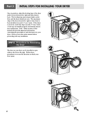
... of the dryer until it is not level, and if the slope exceeds 2.5 cm (1 inch), a load may not tumble properly and internal sensors may malfunction. Part 3 INITIAL STEPS FOR INSTALLING YOUR DRYER Once in which your dryer. The maximum slope of and clearances for Reversing the Door The door on the...
... of the dryer until it is not level, and if the slope exceeds 2.5 cm (1 inch), a load may not tumble properly and internal sensors may malfunction. Part 3 INITIAL STEPS FOR INSTALLING YOUR DRYER Once in which your dryer. The maximum slope of and clearances for Reversing the Door The door on the...
Owners Manual
Page 9
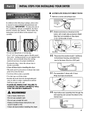
.... Please follow these instructions can result in order to the internal duct. 9 Wrap duct tape around joint. 3-2. I ALTERNATE EXHAUST DIRECTIONS 1. Part 3 INITIAL STEPS FOR INSTALLING YOUR DRYER STEP 3 Connecting the Exhaust and Venting System. Pre-assemble 4" elbow with the dryer, and you should... obtain the venting materials necessary for proper installation) • Position the dryer where the exhaust duct is a SVC part) 3-1. WARNING! • Use a heavy metal vent. • Do not use a plastic vent. • Do not use thin plastic or foil ...
.... Please follow these instructions can result in order to the internal duct. 9 Wrap duct tape around joint. 3-2. I ALTERNATE EXHAUST DIRECTIONS 1. Part 3 INITIAL STEPS FOR INSTALLING YOUR DRYER STEP 3 Connecting the Exhaust and Venting System. Pre-assemble 4" elbow with the dryer, and you should... obtain the venting materials necessary for proper installation) • Position the dryer where the exhaust duct is a SVC part) 3-1. WARNING! • Use a heavy metal vent. • Do not use a plastic vent. • Do not use thin plastic or foil ...
Owners Manual
Page 10
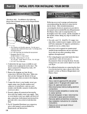
... neutral. 3. Label all pipe connections (both internal and external) for checking inlet gas pressure) 3. Gas Connection 1. The dryer is provided inside the dryer control hood. Part 3 INITIAL STEPS FOR INSTALLING YOUR DRYER STEP 4 Connection of connector only if allowed by your laundry room's gas supply using a new flexible stainless steel connector...
... neutral. 3. Label all pipe connections (both internal and external) for checking inlet gas pressure) 3. Gas Connection 1. The dryer is provided inside the dryer control hood. Part 3 INITIAL STEPS FOR INSTALLING YOUR DRYER STEP 4 Connection of connector only if allowed by your laundry room's gas supply using a new flexible stainless steel connector...
Owners Manual
Page 11
...pressure in your dryer's Electrical Requirements. Effective dryer operation requires appropriate dryer airflow. Static pressure in the operating instructions that accompany the dryer. Part 3 INITIAL STEPS FOR INSTALLING YOUR DRYER STEP 6 Preparation of the dryer. Plug-in the exhaust duct should not exceed 0.6 inches (1.5 cm... burner have accumulated the inside of the Dryer. The exhaust air or the exhaust pipe should be warm after reviewing the following parts on the exhaust duct approximately 2 ft. (60.9 cm) from the inside of the dryer drum/drying compartment any dust or...
...pressure in your dryer's Electrical Requirements. Effective dryer operation requires appropriate dryer airflow. Static pressure in the operating instructions that accompany the dryer. Part 3 INITIAL STEPS FOR INSTALLING YOUR DRYER STEP 6 Preparation of the dryer. Plug-in the exhaust duct should not exceed 0.6 inches (1.5 cm... burner have accumulated the inside of the Dryer. The exhaust air or the exhaust pipe should be warm after reviewing the following parts on the exhaust duct approximately 2 ft. (60.9 cm) from the inside of the dryer drum/drying compartment any dust or...
Owners Manual
Page 12
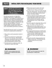
... with metal screws or fasteners that will comply with the Manufactured Home Construction and Safety Standards Title 24 CFR, Part 32-80 or Standard CAN/CSA0Z240 MH and local codes and ordinances. Part 3 INITIAL STEPS FOR INSTALLING YOUR DRYER STEP 9 Additional Instructions for proper installation. ! The opening for an electric dryer must...
... with metal screws or fasteners that will comply with the Manufactured Home Construction and Safety Standards Title 24 CFR, Part 32-80 or Standard CAN/CSA0Z240 MH and local codes and ordinances. Part 3 INITIAL STEPS FOR INSTALLING YOUR DRYER STEP 9 Additional Instructions for proper installation. ! The opening for an electric dryer must...
Owners Manual
Page 13
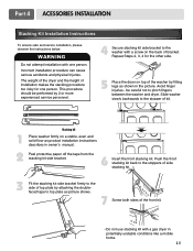
.... 13 Incorrect installation procedure can cause serious accidents and physical Injuries. Avoid finger injuries - This procedure should be careful not to the stopper of bracket. Part 4 ACESSORIES INSTALLATION Stacking Kit Installation Instructions To ensure safe and secure installation, please observe the instructions below. Slide washer slowly backwards to pinch fingers between...
.... 13 Incorrect installation procedure can cause serious accidents and physical Injuries. Avoid finger injuries - This procedure should be careful not to the stopper of bracket. Part 4 ACESSORIES INSTALLATION Stacking Kit Installation Instructions To ensure safe and secure installation, please observe the instructions below. Slide washer slowly backwards to pinch fingers between...
Owners Manual
Page 15
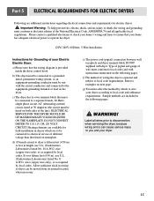
... servicing the dryer, because wiring errors can be moved from its own terminal block that listed on the following pages. ! Label all applicable local regulations. Part 5 ELECTRICAL REQUIREMENTS FOR ELECTRIC DRYERS Following are to be connected to you and your dryer. 15 Heating elements are included in wiring so dryer can...
... servicing the dryer, because wiring errors can be moved from its own terminal block that listed on the following pages. ! Label all applicable local regulations. Part 5 ELECTRICAL REQUIREMENTS FOR ELECTRIC DRYERS Following are to be connected to you and your dryer. 15 Heating elements are included in wiring so dryer can...
Owners Manual
Page 16
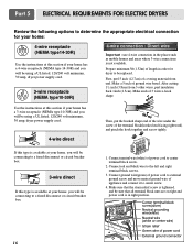
... 3 other wires. peel insulation back 1inch (2.5cm). Connect neutral wire(white) of 3 wires a hook shape. Connect red and black wire to center terminal block screw. 2. Part 5 ELECTRICAL REQUIREMENTS FOR ELECTRIC DRYERS Review the following options to determine the appropriate electrical connection for dryer to be connecting to a fused disconnect or circuit...
... 3 other wires. peel insulation back 1inch (2.5cm). Connect neutral wire(white) of 3 wires a hook shape. Connect red and black wire to center terminal block screw. 2. Part 5 ELECTRICAL REQUIREMENTS FOR ELECTRIC DRYERS Review the following options to determine the appropriate electrical connection for dryer to be connecting to a fused disconnect or circuit...
Owners Manual
Page 17
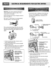
.... Option 1: 4-wire connection with a Power supply cord. • lf your local codes or ordinances do not allow the use of power cord to center screw. 4. Part 5 ELECTRICAL REQUIREMENTS FOR ELECTRIC DRYERS 3-wire connection : Direct wire Important : use a 4wire connection.
.... Option 1: 4-wire connection with a Power supply cord. • lf your local codes or ordinances do not allow the use of power cord to center screw. 4. Part 5 ELECTRICAL REQUIREMENTS FOR ELECTRIC DRYERS 3-wire connection : Direct wire Important : use a 4wire connection.
Owners Manual
Page 18
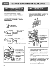
... that the strain relief screw is in right position. 5. Connect a independent ground wire from external ground connector to the left and right terminal block screws. 4. Part 5 ELECTRICAL REQUIREMENTS FOR ELECTRIC DRYERS Option 2: 3-Wire Connection with a Power Supply Cord lf your local codes or ordinances permit the connection of power cord to...
... that the strain relief screw is in right position. 5. Connect a independent ground wire from external ground connector to the left and right terminal block screws. 4. Part 5 ELECTRICAL REQUIREMENTS FOR ELECTRIC DRYERS Option 2: 3-Wire Connection with a Power Supply Cord lf your local codes or ordinances permit the connection of power cord to...
Owners Manual
Page 19
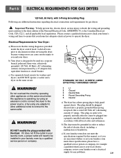
... need to the same outlet. ! b) The dryer must be installed in order to ensure that is operating, by operating other appliances on the same circuit. ! Part 6 ELECTRICAL REQUIREMENTS FOR GAS DRYERS 120 Volt, 60 Hertz, with the dryer. Label all wires prior to disconnection when servicing the dryer, because wiring errors...
... need to the same outlet. ! b) The dryer must be installed in order to ensure that is operating, by operating other appliances on the same circuit. ! Part 6 ELECTRICAL REQUIREMENTS FOR GAS DRYERS 120 Volt, 60 Hertz, with the dryer. Label all wires prior to disconnection when servicing the dryer, because wiring errors...
Owners Manual
Page 20
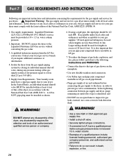
... gas supplier, 3/8 inch approved tubing may be installed within at test pressure equal to do so can result in . pipe plug must be 1/2 inch IPS. Part 7 GAS REQUIREMENTS AND INSTRUCTIONS Following are less than 2/1 psi (3.45 kPa). 5. Gas supply requirements: Liquefied Petroleum (L.P.) Gas (2,500 Btu/ft3 (93.1 MJ/m3)) service must...
... gas supplier, 3/8 inch approved tubing may be installed within at test pressure equal to do so can result in . pipe plug must be 1/2 inch IPS. Part 7 GAS REQUIREMENTS AND INSTRUCTIONS Following are less than 2/1 psi (3.45 kPa). 5. Gas supply requirements: Liquefied Petroleum (L.P.) Gas (2,500 Btu/ft3 (93.1 MJ/m3)) service must...
Owners Manual
Page 21
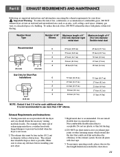
....7 m) 35 feet (10.7 m) 30 feet (9.1 m) 25 feet (7.6 m) 20 feet (6.1 m) 35 feet (10.7 m) 27 feet (8.2 m) 21 feet (6.4 m) 17 feet (5.2 m) 15 feet (4.5m) Exhaust Requirements and Instructions: 1. Part 8 EXHAUST REQUIREMENTS AND MAINTENANCE Following are not provided with duct tape. 5. Do not install flexible duct in diameter with plastic or thin foil ducting. Secure...
....7 m) 35 feet (10.7 m) 30 feet (9.1 m) 25 feet (7.6 m) 20 feet (6.1 m) 35 feet (10.7 m) 27 feet (8.2 m) 21 feet (6.4 m) 17 feet (5.2 m) 15 feet (4.5m) Exhaust Requirements and Instructions: 1. Part 8 EXHAUST REQUIREMENTS AND MAINTENANCE Following are not provided with duct tape. 5. Do not install flexible duct in diameter with plastic or thin foil ducting. Secure...
Owners Manual
Page 22
... clean, pull the lint screen straight up on the dryer, because these articles, such as new towels. 5. In the event lint falls off the screen. Part 8 EXHAUST REQUIREMENTS AND MAINTENANCE Exhaust and Dryer Maintenance ! Please note that nothing has been set against the dampers. 4. Clean the lint filter either before starting...
... clean, pull the lint screen straight up on the dryer, because these articles, such as new towels. 5. In the event lint falls off the screen. Part 8 EXHAUST REQUIREMENTS AND MAINTENANCE Exhaust and Dryer Maintenance ! Please note that nothing has been set against the dampers. 4. Clean the lint filter either before starting...
Owners Manual
Page 23
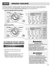
.... Do not dry anything flammable on it (even after each cycle. 2. Fire Hazard No washer can result in death or fire. 23 DLE5977W/DLG5988W/DLE5977B/DLG5988B DLE3777W/DLG3788W STARTING YOUR DRYER 1. Do not dry anything that has ever had anything that has ever had any type of fire, electric.... Turn the knob to follow these instructions can completely remove oil. Failure to select the drying cycle you want. Using Your Dryer 1. Part 9 OPERATING YOUR DRYER Following are instructions for starting and using an Air Cycle. Place laundry into dryer and shut door.
.... Do not dry anything flammable on it (even after each cycle. 2. Fire Hazard No washer can result in death or fire. 23 DLE5977W/DLG5988W/DLE5977B/DLG5988B DLE3777W/DLG3788W STARTING YOUR DRYER 1. Do not dry anything that has ever had anything that has ever had any type of fire, electric.... Turn the knob to follow these instructions can completely remove oil. Failure to select the drying cycle you want. Using Your Dryer 1. Part 9 OPERATING YOUR DRYER Following are instructions for starting and using an Air Cycle. Place laundry into dryer and shut door.


