Owner's Manual
Page 6
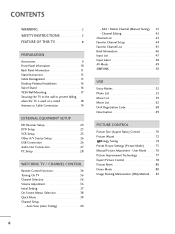
...50 USB Entry Modes 52 Photo List 53 Music List 59 Movie List 62 DivX Registration Code 68 Deactivation 69 PICTURE CONTROL Picture Size (Aspect Ratio) Control 70 Picture Wizard 72 Energy Saving 74 Preset Picture Settings (Picture Mode 75 Manual Picture Adjustment - User Mode 76 ...Setup 23 VCR Setup 25 Other A/V Source Setup 26 USB Connection 26 Audio Out Connection 27 PC Setup 28 WATCHING TV / CHANNEL CONTROL Remote Control Functions 34 Turning On TV 36 Channel Selection 36 Volume Adjustment 36 Initial Setting 37 On-Screen Menus Selection 38 Quick Menu 39 Channel ...
...50 USB Entry Modes 52 Photo List 53 Music List 59 Movie List 62 DivX Registration Code 68 Deactivation 69 PICTURE CONTROL Picture Size (Aspect Ratio) Control 70 Picture Wizard 72 Energy Saving 74 Preset Picture Settings (Picture Mode 75 Manual Picture Adjustment - User Mode 76 ...Setup 23 VCR Setup 25 Other A/V Source Setup 26 USB Connection 26 Audio Out Connection 27 PC Setup 28 WATCHING TV / CHANNEL CONTROL Remote Control Functions 34 Turning On TV 36 Channel Selection 36 Volume Adjustment 36 Initial Setting 37 On-Screen Menus Selection 38 Quick Menu 39 Channel ...
Owner's Manual
Page 9
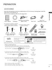
...Owner's Manual Protection Cover and Tape CD Manual (Refer to P.14) Power Cord (For 42/50PT200, 42/50PT330, 42/50PT350, 42/50PT350C, 42/50PT250U, 50PV400, (For 60PV400, 60PV430, 60PV450, 50PV430, 50PV450, 50PV450C, 50PV550U) 60PV450C, 60PV550U) Ferrite Core (Depending on model) x 4 x 3 M4x26 M5x14.5 Screws...ferrite core close to the TV. [to an External device] 10 mm (+/-5 mm) [to P.13, 14) 1.5V 1.5V Power Cord Holder Remote Control, Batteries (AAA) Cable Holder * Wipe spots on the ferrite core thrice. If an accessory is one ferrite core, follow as shown in Figures...
...Owner's Manual Protection Cover and Tape CD Manual (Refer to P.14) Power Cord (For 42/50PT200, 42/50PT330, 42/50PT350, 42/50PT350C, 42/50PT250U, 50PV400, (For 60PV400, 60PV430, 60PV450, 50PV430, 50PV450, 50PV450C, 50PV550U) 60PV450C, 60PV550U) Ferrite Core (Depending on model) x 4 x 3 M4x26 M5x14.5 Screws...ferrite core close to the TV. [to an External device] 10 mm (+/-5 mm) [to P.13, 14) 1.5V 1.5V Power Cord Holder Remote Control, Batteries (AAA) Cable Holder * Wipe spots on the ferrite core thrice. If an accessory is one ferrite core, follow as shown in Figures...
Owner's Manual
Page 10
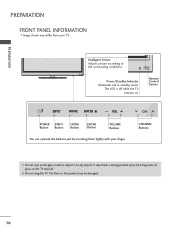
PREPARATION PREPARATION FRONT PANEL INFORMATION s Image shown may fall. Remote Control Sensor HOME ENTER VOL CH POWER INPUT Button Button HOME Button ENTER Button VOLUME Buttons You can operate the buttons just by touching them lightly ...
PREPARATION PREPARATION FRONT PANEL INFORMATION s Image shown may fall. Remote Control Sensor HOME ENTER VOL CH POWER INPUT Button Button HOME Button ENTER Button VOLUME Buttons You can operate the buttons just by touching them lightly ...
Owner's Manual
Page 12
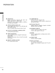
...Optical digital audio output for use with amps and home theater systems. Note: In standby mode, this port doesn't work. 3 RS-232C IN (CONTROL & SERVICE) PORT Used by third party devices. 4 AUDIO IN (RGB/DVI) 1/8" headphone jack for software updates. 11 Power Cord Socket For ... & red and white for audio. 7 AV (Audio/Video) IN Analog composite connection. Uses a D-sub 15 pin cable (VGA cable). 5 REMOTE CONTROL IN PORT For a wired remote control. 6 COMPONENT IN Analog Connection. Supports standard definition video only (480i). 8 ANTENNA/CABLE IN Connect over-the air signals to this jack. 9 ...
...Optical digital audio output for use with amps and home theater systems. Note: In standby mode, this port doesn't work. 3 RS-232C IN (CONTROL & SERVICE) PORT Used by third party devices. 4 AUDIO IN (RGB/DVI) 1/8" headphone jack for software updates. 11 Power Cord Socket For ... & red and white for audio. 7 AV (Audio/Video) IN Analog composite connection. Uses a D-sub 15 pin cable (VGA cable). 5 REMOTE CONTROL IN PORT For a wired remote control. 6 COMPONENT IN Analog Connection. Supports standard definition video only (480i). 8 ANTENNA/CABLE IN Connect over-the air signals to this jack. 9 ...
Owner's Manual
Page 20
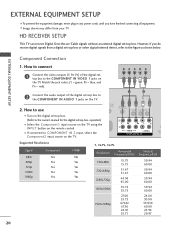
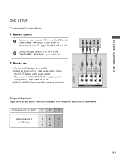
... colors (Y = green, PB = blue, and PR = red). operation) s Select the Component1 input source on the TV using the INPUT button on the TV. 1 2 O IN /DVI) REMOTE CONTROL IN AV IN 1 VIDEO /MONO AUDIO 2 L R 1 VIDEO AUDIO COMPONENT IN ANT CA Supported Resolutions Signal 480i 480p 720p 1080i 1080p Component Yes Yes Yes Yes... from your TV. Y PB PR L R 2 Connect the audio output of the digital settop box to COMPONENT IN 2 input, select the Component2 input source on the remote control. EXTERNAL EQUIPMENT SETUP Component Connection 1.
... colors (Y = green, PB = blue, and PR = red). operation) s Select the Component1 input source on the TV using the INPUT button on the TV. 1 2 O IN /DVI) REMOTE CONTROL IN AV IN 1 VIDEO /MONO AUDIO 2 L R 1 VIDEO AUDIO COMPONENT IN ANT CA Supported Resolutions Signal 480i 480p 720p 1080i 1080p Component Yes Yes Yes Yes... from your TV. Y PB PR L R 2 Connect the audio output of the digital settop box to COMPONENT IN 2 input, select the Component2 input source on the remote control. EXTERNAL EQUIPMENT SETUP Component Connection 1.
Owner's Manual
Page 21
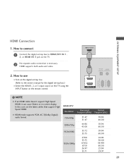
... the latest cables that support High Speed HDMI. HDMI supports both audio and video. 2. How to HDMI/DVI IN 1, 2, or HDMI IN 3 jack on the remote control. HDMI-DTV OUTPUT 1 OPTICAL DIGITAL AUDIO AUDIO OUT (RGB/DVI) 2 1 HDMI/DVI IN RS-232C IN...
... the latest cables that support High Speed HDMI. HDMI supports both audio and video. 2. How to HDMI/DVI IN 1, 2, or HDMI IN 3 jack on the remote control. HDMI-DTV OUTPUT 1 OPTICAL DIGITAL AUDIO AUDIO OUT (RGB/DVI) 2 1 HDMI/DVI IN RS-232C IN...
Owner's Manual
Page 22
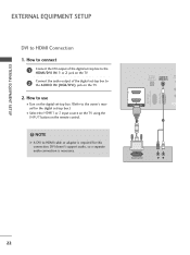
EXTERNAL EQUIPMENT SETUP EXTERNAL EQUIPMENT SETUP DVI to the AUDIO IN (RGB/DVI) jack on the remote control. ! How to connect 1 Connect the DVI output of the digital set-top box to the HDMI/DVI IN 1 or 2 jack on the TV. 2 Connect the ... connection is required for the digital set -top box to HDMI Connection 1. OPTICAL DIGITAL AUDIO IN RE CON AUDIO OUT (RGB/DVI) RS-232C IN (CONTROL & SERVICE) RGB IN (PC) 2 2 1 1 HDMI/DVI IN 1 2 DVI-DTV OUTPUT R L 22
EXTERNAL EQUIPMENT SETUP EXTERNAL EQUIPMENT SETUP DVI to the AUDIO IN (RGB/DVI) jack on the remote control. ! How to connect 1 Connect the DVI output of the digital set-top box to the HDMI/DVI IN 1 or 2 jack on the TV. 2 Connect the ... connection is required for the digital set -top box to HDMI Connection 1. OPTICAL DIGITAL AUDIO IN RE CON AUDIO OUT (RGB/DVI) RS-232C IN (CONTROL & SERVICE) RGB IN (PC) 2 2 1 1 HDMI/DVI IN 1 2 DVI-DTV OUTPUT R L 22
Owner's Manual
Page 23
... to connect 1 Connect the video outputs (Y, PB, PR) of the DVD to the DVD player's manual for operating instructions. DIO IN B/DVI) REMOTE CONTROL IN AV IN 1 VIDEO /MONO AUDIO 2 L R 1 VIDEO AUDIO A COMPONENT IN Component Input ports To get better picture quality, connect a .... Y PB PR L R 1 2 2. I If connected to use I Turn on the TV. Component ports on the TV Y Y Video output ports Y on the remote control. How to COMPONENT IN 2 input, select the Component2 input source on the TV. I Select the Component1 input source on the TV using the INPUT button...
... to connect 1 Connect the video outputs (Y, PB, PR) of the DVD to the DVD player's manual for operating instructions. DIO IN B/DVI) REMOTE CONTROL IN AV IN 1 VIDEO /MONO AUDIO 2 L R 1 VIDEO AUDIO A COMPONENT IN Component Input ports To get better picture quality, connect a .... Y PB PR L R 1 2 2. I If connected to use I Turn on the TV. Component ports on the TV Y Y Video output ports Y on the remote control. How to COMPONENT IN 2 input, select the Component2 input source on the TV. I Select the Component1 input source on the TV using the INPUT button...
Owner's Manual
Page 24
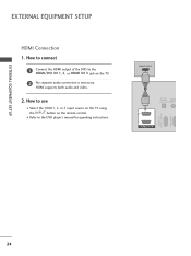
I Select the HDMI1, 2, or 3 input source on the TV using the INPUT button on the TV. 2 No separate audio connection is necessary. How to connect 1 Connect the HDMI output of the DVD to the DVD player's manual for operating instructions. How to use I Refer to the HDMI/DVI IN 1, 2, or HDMI IN 3 jack on the remote control. HDMI-DTV OUTPUT 1 OPTICAL DIGITAL AUDIO AUDIO OUT (RGB/DV 2 1 HDMI/DVI IN RS-232C IN (CONTROL & SERVICE) RGB IN(PC) 24 EXTERNAL EQUIPMENT SETUP EXTERNAL EQUIPMENT SETUP HDMI Connection 1. HDMI supports both audio and video. 2.
I Select the HDMI1, 2, or 3 input source on the TV using the INPUT button on the TV. 2 No separate audio connection is necessary. How to connect 1 Connect the HDMI output of the DVD to the DVD player's manual for operating instructions. How to use I Refer to the HDMI/DVI IN 1, 2, or HDMI IN 3 jack on the remote control. HDMI-DTV OUTPUT 1 OPTICAL DIGITAL AUDIO AUDIO OUT (RGB/DV 2 1 HDMI/DVI IN RS-232C IN (CONTROL & SERVICE) RGB IN(PC) 24 EXTERNAL EQUIPMENT SETUP EXTERNAL EQUIPMENT SETUP HDMI Connection 1. HDMI supports both audio and video. 2.
Owner's Manual
Page 25
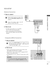
... in socket of the TV. (PC) ANT IN S-VIDEO VIDEO L R ANT OUT OUTPUT SWITCH 1 UDIO B/DVI) REMOTE CONTROL IN AV IN 1 VIDEO L/MONO AUDIO R 2 L R 1 25 I Insert a video tape into the VCR and press PLAY on the remote control. How to use I Select the A V 1 input source on the TV using the INPUT button on the...
... in socket of the TV. (PC) ANT IN S-VIDEO VIDEO L R ANT OUT OUTPUT SWITCH 1 UDIO B/DVI) REMOTE CONTROL IN AV IN 1 VIDEO L/MONO AUDIO R 2 L R 1 25 I Insert a video tape into the VCR and press PLAY on the remote control. How to use I Select the A V 1 input source on the TV using the INPUT button on the...
Owner's Manual
Page 26
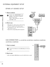
... equipment. For 42/50PT350, 42/50PT350C, 50/60PV450, 50/60PV450C, 42/50PT250U, 50/60PV550U 1. How to AV IN 1 input, select the A V 1 input source on the remote control. How to use the USB function. (G p.52) AV IN 2 26 I N jack, you use I Select the A V 2 input source on the TV using the INPUT button on...
... equipment. For 42/50PT350, 42/50PT350C, 50/60PV450, 50/60PV450C, 42/50PT250U, 50/60PV550U 1. How to AV IN 1 input, select the A V 1 input source on the remote control. How to use the USB function. (G p.52) AV IN 2 26 I N jack, you use I Select the A V 2 input source on the TV using the INPUT button on...
Owner's Manual
Page 28
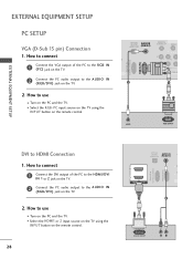
...jack on the TV. 2. OPTICAL DIGITAL AUDIO OUT AUDIO IN (RGB/DVI) REMOTE CONTROL IN VIDEO 2 2 1 VIDEO COMPONEN 1 RS-232C IN (CONTROL & SERVICE) RGB IN (PC) 2 1 AUDIO RGB OUTPUT DVI to the AUDIO IN (RGB/DVI) jack on the remote control. I Turn on the PC and the TV. How to use I Select ...HDMI Connection 1. How to connect 1 Connect the VGA output of the PC to the HDMI/DVI IN 1 or 2 jack on the remote control. 28 OPTICAL DIGITAL AUDIO IN C AUDIO OUT (RGB/DVI) RS-232C IN (CONTROL & SERVICE) RGB IN (PC) 2 2 1 1 HDMI/DVI IN 1 2 DVI-DTV OUTPUT R L I Turn on the PC...
...jack on the TV. 2. OPTICAL DIGITAL AUDIO OUT AUDIO IN (RGB/DVI) REMOTE CONTROL IN VIDEO 2 2 1 VIDEO COMPONEN 1 RS-232C IN (CONTROL & SERVICE) RGB IN (PC) 2 1 AUDIO RGB OUTPUT DVI to the AUDIO IN (RGB/DVI) jack on the remote control. I Turn on the PC and the TV. How to use I Select ...HDMI Connection 1. How to connect 1 Connect the VGA output of the PC to the HDMI/DVI IN 1 or 2 jack on the remote control. 28 OPTICAL DIGITAL AUDIO IN C AUDIO OUT (RGB/DVI) RS-232C IN (CONTROL & SERVICE) RGB IN (PC) 2 2 1 1 HDMI/DVI IN 1 2 DVI-DTV OUTPUT R L I Turn on the PC...
Owner's Manual
Page 34
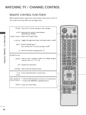
...Depending on the TV. Color Access special functions in some menus. WATCHING TV / CHANNEL CONTROL WATCHING TV / CHANNEL CONTROL REMOTE CONTROL FUNCTIONS When using the remote control, aim it at the remote control sensor on Model) ENERGY SAVING Adjusts the Energy Saving. LIST Displays the channel list....MODE Toggles through inputs. G p.47 TV Select the remote operating mode: TV NUMBER button - (DASH) Used to the last channel viewed. The remote control may differ from standby or off to standby. Control buttons Controls the SIMPLINK compatible devices. POWER Turns the TV on ...
...Depending on the TV. Color Access special functions in some menus. WATCHING TV / CHANNEL CONTROL WATCHING TV / CHANNEL CONTROL REMOTE CONTROL FUNCTIONS When using the remote control, aim it at the remote control sensor on Model) ENERGY SAVING Adjusts the Energy Saving. LIST Displays the channel list....MODE Toggles through inputs. G p.47 TV Select the remote operating mode: TV NUMBER button - (DASH) Used to the last channel viewed. The remote control may differ from standby or off to standby. Control buttons Controls the SIMPLINK compatible devices. POWER Turns the TV on ...
Owner's Manual
Page 36
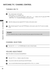
... to turn TV on, press the , INPUT, CH ( or ) button on the TV or press the POWER, INPUT, CH( or ), Number (0~9) button on the remote control. 2 Select the viewing source by pressing the MUTE or VOL (+ or -) button. 36 At this moment, TV is in standby mode. The TV reverts to... select a channel number. NOTE G If you want to be away on the remote control. CHANNEL SELECTION 1 Press the CH ( or ) or NUMBER buttons to standby mode. ! VOLUME ADJUSTMENT Adjust the volume to suit your personal preference. 1 Press the ...
... to turn TV on, press the , INPUT, CH ( or ) button on the TV or press the POWER, INPUT, CH( or ), Number (0~9) button on the remote control. 2 Select the viewing source by pressing the MUTE or VOL (+ or -) button. 36 At this moment, TV is in standby mode. The TV reverts to... select a channel number. NOTE G If you want to be away on the remote control. CHANNEL SELECTION 1 Press the CH ( or ) or NUMBER buttons to standby mode. ! VOLUME ADJUSTMENT Adjust the volume to suit your personal preference. 1 Press the ...

Owner's Manual
Page 50
WATCHING TV / CHANNEL CONTROL OPTION Language Input Label SIMPLINK Key Lock Caption Demo Mode ISM Method Set ID Initial Setting Move Enter : On...the user menus. G When you switch the Input source with the HDMI cable. SIMPLINK can be turned on the remote control, the SIMPLINK device will stop. NOTE G Connect the HDMI/DVI IN or HDMI IN terminal of the TV to...CEC support, but only devices with HDMI cable without additional cables and settings. WATCHING TV / CHANNEL CONTROL Simplink allows you to control and play the audio from the TV, connect the DIGITAL AUDIO OUT terminal on the back of...
WATCHING TV / CHANNEL CONTROL OPTION Language Input Label SIMPLINK Key Lock Caption Demo Mode ISM Method Set ID Initial Setting Move Enter : On...the user menus. G When you switch the Input source with the HDMI cable. SIMPLINK can be turned on the remote control, the SIMPLINK device will stop. NOTE G Connect the HDMI/DVI IN or HDMI IN terminal of the TV to...CEC support, but only devices with HDMI cable without additional cables and settings. WATCHING TV / CHANNEL CONTROL Simplink allows you to control and play the audio from the TV, connect the DIGITAL AUDIO OUT terminal on the back of...

Owner's Manual
Page 53
... PHOTO LIST You can play JPG files only. Supported photo file: *.JPG I Only baseline scan is supported among JPG. The On Screen Display on the remote control. PHOTO LIST Top Folder DriveA 3 4 Page 1/1 No Marked DriveA 1 2 folder, 4 file(s) Up Folder Move PopUp Menu 6 CH Move Page MARK Mark 5 USB Device Free Space...
... PHOTO LIST You can play JPG files only. Supported photo file: *.JPG I Only baseline scan is supported among JPG. The On Screen Display on the remote control. PHOTO LIST Top Folder DriveA 3 4 Page 1/1 No Marked DriveA 1 2 folder, 4 file(s) Up Folder Move PopUp Menu 6 CH Move Page MARK Mark 5 USB Device Free Space...

Owner's Manual
Page 59
... rate range 8Kbps - 320Kbps • Sampling rate (Sampling Frequency) MPEG1Layer 3: 8KHz - 48KHz • Music Max Length: 999.59 Sec. The On Screen Display on the remote control.
... rate range 8Kbps - 320Kbps • Sampling rate (Sampling Frequency) MPEG1Layer 3: 8KHz - 48KHz • Music Max Length: 999.59 Sec. The On Screen Display on the remote control.

Owner's Manual
Page 63
...: Display the title/folder name of the movie in the same folder. G The name of marked movie files. 5 Usable USB memory. 1 6 Corresponding buttons on the remote control. NOTE G The video file and the subtitle file must be located in the selected folder. 3 Current page/Total pages. 2 4 Total number of the video file...
...: Display the title/folder name of the movie in the same folder. G The name of marked movie files. 5 Usable USB memory. 1 6 Corresponding buttons on the remote control. NOTE G The video file and the subtitle file must be located in the selected folder. 3 Current page/Total pages. 2 4 Total number of the video file...

Owner's Manual
Page 65
NOTE G Use the ( / ) bottons to move to normal playback. ! USB Using the remote control You can adjust various method during playback a cursor indicating the position can be viewed on the screen. I When using the or buttons during movie play. ...
NOTE G Use the ( / ) bottons to move to normal playback. ! USB Using the remote control You can adjust various method during playback a cursor indicating the position can be viewed on the screen. I When using the or buttons during movie play. ...
Owner's Manual
Page 70
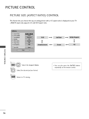
... 2 Select the Aspect Ratio. Select the desired picture format. 3 EXIT Return to TV viewing. PICTURE CONTROL PICTURE SIZE (ASPECT RATIO) CONTROL This feature lets you choose the way an analog picture with a 4:3 aspect ratio is displayed on the remote control. s RGB-PC input only supports 4:3 and 16:9 aspect ratio. s You can also press the...
... 2 Select the Aspect Ratio. Select the desired picture format. 3 EXIT Return to TV viewing. PICTURE CONTROL PICTURE SIZE (ASPECT RATIO) CONTROL This feature lets you choose the way an analog picture with a 4:3 aspect ratio is displayed on the remote control. s RGB-PC input only supports 4:3 and 16:9 aspect ratio. s You can also press the...


