
Owner's Manual
Page 3
OWNER'S MANUAL PLASMA TV Please read this manual carefully before operating your set and retain it for future reference. 42PJ250 50PJ250 50PK250 60PK250 60PK280 60PK290 42PJ340 50PJ340 42PJ350 50PJ350 50PK350 50PK340 50PK540 60PK540 42PJ550 50PJ550 42PJ550 50PJ550 50PK550 60PK550 42PJ350C 50PJ350C 50PK550C 60PK550C P/NO : MFL62861002 (1004-REV02) www.lg.com
OWNER'S MANUAL PLASMA TV Please read this manual carefully before operating your set and retain it for future reference. 42PJ250 50PJ250 50PK250 60PK250 60PK280 60PK290 42PJ340 50PJ340 42PJ350 50PJ350 50PK350 50PK340 50PK540 60PK540 42PJ550 50PJ550 42PJ550 50PJ550 50PK550 60PK550 42PJ350C 50PJ350C 50PK550C 60PK550C P/NO : MFL62861002 (1004-REV02) www.lg.com
Owner's Manual
Page 4
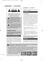
...- If this product IMPORTANT INFORMATION TO PREVENT "IMAGE BURN / BURN-IN" ON YOUR TV SCREEN I In order to prevent image burn, avoid displaying a fixed image on a circuit different from LG Electronics. This phenomenon is encouraged to try to correct the interference by the party responsible... modification could void the user's authority to operate the equipment. I When a fixed image (e.g. Connect the equipment to an outlet on your TV if you use the 4:3 aspect ratio setting for Plasma). I Image burn can also occur on the screen. NO USER SERVICEABLE PARTS INSIDE....
...- If this product IMPORTANT INFORMATION TO PREVENT "IMAGE BURN / BURN-IN" ON YOUR TV SCREEN I In order to prevent image burn, avoid displaying a fixed image on a circuit different from LG Electronics. This phenomenon is encouraged to try to correct the interference by the party responsible... modification could void the user's authority to operate the equipment. I When a fixed image (e.g. Connect the equipment to an outlet on your TV if you use the 4:3 aspect ratio setting for Plasma). I Image burn can also occur on the screen. NO USER SERVICEABLE PARTS INSIDE....
Owner's Manual
Page 5
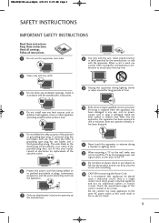
...MFL62861002-en-simple 4/21/10 11:53 AM Page 3 SAFETY INSTRUCTIONS IMPORTANT SAFETY INSTRUCTIONS Read these instructions. Heed all servicing to install the TV by the manufacturer. 10 Refer all warnings. Check the specification page of time. 4 Do not install near water. 8 Use only with ...by the manufacturer, or sold with the manufacturer's instructions. 9 Unplug this apparatus during a thunder or lighting storm. 12 When mounting a TV on the wall, make sure not to qualified service personnel. Do not connect too many appliances to the same AC power outlet as this ...
...MFL62861002-en-simple 4/21/10 11:53 AM Page 3 SAFETY INSTRUCTIONS IMPORTANT SAFETY INSTRUCTIONS Read these instructions. Heed all servicing to install the TV by the manufacturer. 10 Refer all warnings. Check the specification page of time. 4 Do not install near water. 8 Use only with ...by the manufacturer, or sold with the manufacturer's instructions. 9 Unplug this apparatus during a thunder or lighting storm. 12 When mounting a TV on the wall, make sure not to qualified service personnel. Do not connect too many appliances to the same AC power outlet as this ...
Owner's Manual
Page 6
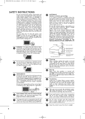
...and all cables have been removed. Any of overhead power lines or other liquids. Antenna grounding according to prevent possible electric shock (i.e. on the TV as being twisted, kinked, pinched, closed in contact with respect to proper grounding of the mast and supporting structure, grounding of the lead-..., connection to telephone wires, lightening rods, or gas pipes. Be sure the antenna system is the disconnecting device. Do not touch the TV with the power cord plugged in wire to an antenna discharge unit, size of grounding conductors, location of the appliance, and have a ...
...and all cables have been removed. Any of overhead power lines or other liquids. Antenna grounding according to prevent possible electric shock (i.e. on the TV as being twisted, kinked, pinched, closed in contact with respect to proper grounding of the mast and supporting structure, grounding of the lead-..., connection to telephone wires, lightening rods, or gas pipes. Be sure the antenna system is the disconnecting device. Do not touch the TV with the power cord plugged in wire to an antenna discharge unit, size of grounding conductors, location of the appliance, and have a ...
Owner's Manual
Page 7
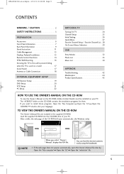
... Instruction 11 Cable Management 13 Desktop Pedestal Installation 13 Remote Control Functions 14 VESA Wall Mounting 16 Securing the TV to the wall to install those programs, Open the "My Computer" Open the "LG" Open the "ACRORD" double-click your language. NOTE When you want to prevent falling when the... TV is used on a stand 17 Swivel Stand 17 Antenna or Cable Connection 18 EXTERNAL EQUIPMENT SETUP HD Receiver ...
... Instruction 11 Cable Management 13 Desktop Pedestal Installation 13 Remote Control Functions 14 VESA Wall Mounting 16 Securing the TV to the wall to install those programs, Open the "My Computer" Open the "LG" Open the "ACRORD" double-click your language. NOTE When you want to prevent falling when the... TV is used on a stand 17 Swivel Stand 17 Antenna or Cable Connection 18 EXTERNAL EQUIPMENT SETUP HD Receiver ...
Owner's Manual
Page 8
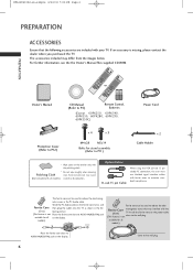
... * Wipe spots on the display. Wind the PC Audio cable on the ferrite core twice, and Ferrite Core then plug the cables into the TV as shown in the PC Audio cable. For further information, see the the Owner's Manual files supplied CD-ROM. ENERGY SAVING 1 AV MODE ... to P.12) x 4 x 3 M4x28 M5x14 Bolts for all on the power cable (This feature is missing, please contact the dealer where you purchased the TV. available for all models) scratch or discoloration. close to AUDIO IN(RGB/DVI) jack available for stand assembly (Refer to the wall plug. Option Extras...
... * Wipe spots on the display. Wind the PC Audio cable on the ferrite core twice, and Ferrite Core then plug the cables into the TV as shown in the PC Audio cable. For further information, see the the Owner's Manual files supplied CD-ROM. ENERGY SAVING 1 AV MODE ... to P.12) x 4 x 3 M4x28 M5x14 Bolts for all on the power cable (This feature is missing, please contact the dealer where you purchased the TV. available for all models) scratch or discoloration. close to AUDIO IN(RGB/DVI) jack available for stand assembly (Refer to the wall plug. Option Extras...

Owner's Manual
Page 9
... lightly with your finger. ENTER VOL CH Power/Standby Indicator Illuminates red in standby mode. The LED is off while the TV remains on . The LED is off while the TV remains on . MFL62861002-en-simple 4/21/10 11:53 AM Page 7 FRONT PANEL INFORMATION I Image shown may differ from... your TV. 50/60PK550, 50/60PK540, 42/50PJ550, 50/60PK550C Intelligent Sensor Adjusts picture according to the surrounding conditions. ENTER VOL CH Power...
... lightly with your finger. ENTER VOL CH Power/Standby Indicator Illuminates red in standby mode. The LED is off while the TV remains on . The LED is off while the TV remains on . MFL62861002-en-simple 4/21/10 11:53 AM Page 7 FRONT PANEL INFORMATION I Image shown may differ from... your TV. 50/60PK550, 50/60PK540, 42/50PJ550, 50/60PK550C Intelligent Sensor Adjusts picture according to the surrounding conditions. ENTER VOL CH Power...

Owner's Manual
Page 10
... red in standby mode. CH CHANNEL Buttons G Do not step on . The floor or the product may fall. G Do not drag the TV. MFL62861002-en-simple 4/21/10 11:53 AM Page 8 PREPARATION PREPARATION 42/50PJ350, 42/50PJ340, 50PK340, 50PK350, 42/50PJ350C Intelligent Sensor Adjusts ...picture according to any impact.It may break, causing possible injury from fragments of glass, or the TV may be damaged. 8 Remote Control Sensor ENTER VOL CH VOL POWER INPUT Button Button MENU Button ENTER Button VOLUME Buttons You can operate...
... red in standby mode. CH CHANNEL Buttons G Do not step on . The floor or the product may fall. G Do not drag the TV. MFL62861002-en-simple 4/21/10 11:53 AM Page 8 PREPARATION PREPARATION 42/50PJ350, 42/50PJ340, 50PK340, 50PK350, 42/50PJ350C Intelligent Sensor Adjusts ...picture according to any impact.It may break, causing possible injury from fragments of glass, or the TV may be damaged. 8 Remote Control Sensor ENTER VOL CH VOL POWER INPUT Button Button MENU Button ENTER Button VOLUME Buttons You can operate...

Owner's Manual
Page 11
... and white for analog PC audio input. Supports standard definition video only (480i). 8 ANTENNA/CABLE IN Connect over-the air signals to operate the TV on DC power. 9 Doesn't support 480i. Uses a D-sub 15 pin cable (VGA cable). Accepts DVI video using an adapter or HDMI to... 6 6 COMPONENT IN Analog Connection. Supports HD. MFL62861002-en-simple 4/21/10 11:53 AM Page 9 PREPARATION BACK PANEL INFORMATION I Image shown may differ from your TV. 42/50PJ250, 50/60PK250, 60PK280, 42/50PJ340, 50/60PK540, 50PK340 R VIDEO L/MONO AUDIO R HDMI IN 3 SERVICE ONLY R R 9 1 7 AV IN 2 10 2 4 5...
... and white for analog PC audio input. Supports standard definition video only (480i). 8 ANTENNA/CABLE IN Connect over-the air signals to operate the TV on DC power. 9 Doesn't support 480i. Uses a D-sub 15 pin cable (VGA cable). Accepts DVI video using an adapter or HDMI to... 6 6 COMPONENT IN Analog Connection. Supports HD. MFL62861002-en-simple 4/21/10 11:53 AM Page 9 PREPARATION BACK PANEL INFORMATION I Image shown may differ from your TV. 42/50PJ250, 50/60PK250, 60PK280, 42/50PJ340, 50/60PK540, 50PK340 R VIDEO L/MONO AUDIO R HDMI IN 3 SERVICE ONLY R R 9 1 7 AV IN 2 10 2 4 5...

Owner's Manual
Page 12
... audio. 7 AV (Audio/Video) IN Analog composite connection. Supports standard definition video only (480i). 8 ANTENNA/CABLE IN Connect over-the air signals to operate the TV on DC power. 10 Uses a red, green, and blue cable for video & red and white for analog PC audio input. Uses a D-sub 15 pin cable...
... audio. 7 AV (Audio/Video) IN Analog composite connection. Supports standard definition video only (480i). 8 ANTENNA/CABLE IN Connect over-the air signals to operate the TV on DC power. 10 Uses a red, green, and blue cable for video & red and white for analog PC audio input. Uses a D-sub 15 pin cable...
Owner's Manual
Page 13
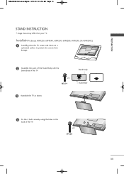
x 3 M5x14 Stand Body Stand Base 3 Assemble the TV as shown. 4 Fix the 4 bolts securely using the holes in the back of the TV. MFL62861002-en-simple 4/21/10 11:54 AM Page 11 PREPARATION STAND INSTRUCTION I Image shown may differ from damage. 2 Assemble the parts of the Stand Body with the Stand Base of the TV. x 4 M4x28 11 Installation (Except 60PK250, 60PK540, 60PK550, 60PK280, 60PK290, 50/60PK550C) 1 Carefully place the TV screen side down on a cushioned surface to protect the screen from your TV.
x 3 M5x14 Stand Body Stand Base 3 Assemble the TV as shown. 4 Fix the 4 bolts securely using the holes in the back of the TV. MFL62861002-en-simple 4/21/10 11:54 AM Page 11 PREPARATION STAND INSTRUCTION I Image shown may differ from damage. 2 Assemble the parts of the Stand Body with the Stand Base of the TV. x 4 M4x28 11 Installation (Except 60PK250, 60PK540, 60PK550, 60PK280, 60PK290, 50/60PK550C) 1 Carefully place the TV screen side down on a cushioned surface to protect the screen from your TV.
Owner's Manual
Page 14
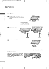
Press the PROTECTION COVER into the TV until you hear it click. 12 PROTECTION COVER (Fix a Guide to protect the screen from damage. 2 Loose the bolts from TV. (42/50PJ250, 50PK250, 42/50PJ340, 42/50PJ350, 50PK350, 50PK340, 50PK540, 42/50PJ550, 50PK550, 42/50PJ350C, 50PK550C) (60PK250..., 60PK540, 60PK550, 60PK280, 60PK290, 60PK550C) 3 Detach the stand from TV. x 4 M4x28 x 5 M4x30 Protection Cover After ...
Press the PROTECTION COVER into the TV until you hear it click. 12 PROTECTION COVER (Fix a Guide to protect the screen from damage. 2 Loose the bolts from TV. (42/50PJ250, 50PK250, 42/50PJ340, 42/50PJ350, 50PK350, 50PK340, 50PK540, 42/50PJ550, 50PK550, 42/50PJ350C, 50PK550C) (60PK250..., 60PK540, 60PK550, 60PK280, 60PK290, 60PK550C) 3 Detach the stand from TV. x 4 M4x28 x 5 M4x30 Protection Cover After ...

Owner's Manual
Page 15
... of heat source. 13 To connect additional equipment, see EXTERNAL EQUIPMENT SETUP section. PREPARATION CABLE HOLDER DESKTOP PEDESTAL INSTALLATION I Image shown may differ from your TV. 1 After connecting the cables as necessary, install CABLE HOLDER as shown and bundle the cables. MFL62861002-en-simple 4/21/10 11:54 AM Page 13...
... of heat source. 13 To connect additional equipment, see EXTERNAL EQUIPMENT SETUP section. PREPARATION CABLE HOLDER DESKTOP PEDESTAL INSTALLATION I Image shown may differ from your TV. 1 After connecting the cables as necessary, install CABLE HOLDER as shown and bundle the cables. MFL62861002-en-simple 4/21/10 11:54 AM Page 13...
Owner's Manual
Page 16
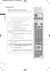
... standby. buttons SIMPLINK FF (Rewind), GG (Fast Forward), G (Playback), l l (Pause) Control buttons Controls the SIMPLINK compatible devices. TV Select the remote operating mode: TV NUMBER button - (DASH) Used to the last channel viewed. LIST Displays the channel list. A (Stop) Stops processing of time machine function.... (Playback, Rewind etc) ENERGY AV MODE INPUT TV SAVING 50/60PK550, 50/60PK540, 50/60PK550C ON/OFF ENERGY AV MODE INPUT TV SAVING 123 456 789 LIST VOL 0 MARK FAV RATIO FLASHBK P CH A G E MUTE MENU INFO Q....
... standby. buttons SIMPLINK FF (Rewind), GG (Fast Forward), G (Playback), l l (Pause) Control buttons Controls the SIMPLINK compatible devices. TV Select the remote operating mode: TV NUMBER button - (DASH) Used to the last channel viewed. LIST Displays the channel list. A (Stop) Stops processing of time machine function.... (Playback, Rewind etc) ENERGY AV MODE INPUT TV SAVING 50/60PK550, 50/60PK540, 50/60PK550C ON/OFF ENERGY AV MODE INPUT TV SAVING 123 456 789 LIST VOL 0 MARK FAV RATIO FLASHBK P CH A G E MUTE MENU INFO Q....

Owner's Manual
Page 17
... batteries with new ones. Right/ENTER) MENU Displays the main menu or clears all on-screen displays and return to TV viewing. MUTE Switches the sound on -screen displays and returns to TV viewing from one step in an interactive application or other user interaction function. VOLUME UP Adjusts the volume. /DOWN...
... batteries with new ones. Right/ENTER) MENU Displays the main menu or clears all on-screen displays and return to TV viewing. MUTE Switches the sound on -screen displays and returns to TV viewing from one step in an interactive application or other user interaction function. VOLUME UP Adjusts the volume. /DOWN...
Owner's Manual
Page 18
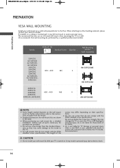
...to other building materials, please contact your nearest installer. G For wall mounts that do not comply with the mount. G LG is not liable for TV damage or personal injury when a non-VESA or non specified wall mount is not liable for assembly are shown in the ...bracket (sold separately) 50PK550, 42/50PJ340 42/50PJ350, 42/50PJ250 50PK250, 50PK340, 50PK350, 400 * 400 M6 50PK540, 42/50PJ550, 42/50PJ350C, 50PK550C 60PK550, 60PK250, 60PK280, 600 * 400 M8 60PK290, 50PK540, 60PK550C AW-50PG60MS 4 AW-50PG60M 4 AW-60PG60MS ! NOTE G Screw length needed depends on a ceiling or ...
...to other building materials, please contact your nearest installer. G For wall mounts that do not comply with the mount. G LG is not liable for TV damage or personal injury when a non-VESA or non specified wall mount is not liable for assembly are shown in the ...bracket (sold separately) 50PK550, 42/50PJ340 42/50PJ350, 42/50PJ250 50PK250, 50PK340, 50PK350, 400 * 400 M6 50PK540, 42/50PJ550, 42/50PJ350C, 50PK550C 60PK550, 60PK250, 60PK280, 600 * 400 M8 60PK290, 50PK540, 60PK550C AW-50PG60MS 4 AW-50PG60M 4 AW-60PG60MS ! NOTE G Screw length needed depends on a ceiling or ...
Owner's Manual
Page 19
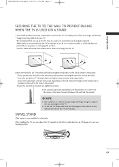
... so it cannot be attached to a wall so it becomes horizontal between the wall and the product. ! It is mounted on or hang from the TV. I Use a sturdy rope (sold separately) to the wall. Additionally, we recommend that children don't climb on the wall to the holes in the ... from tipping over if pushed backwards. Ensure the eye-bolts or brackets are the same. Match the height of the TV. G To use the TV safely, make sure that the TV be pulled in a forward direction, potentially causing injury or damaging the product. PREPARATION MFL62861002-en-simple 4/21/10 11...
... so it cannot be attached to a wall so it becomes horizontal between the wall and the product. ! It is mounted on or hang from the TV. I Use a sturdy rope (sold separately) to the wall. Additionally, we recommend that children don't climb on the wall to the holes in the ... from tipping over if pushed backwards. Ensure the eye-bolts or brackets are the same. Match the height of the TV. G To use the TV safely, make sure that the TV be pulled in a forward direction, potentially causing injury or damaging the product. PREPARATION MFL62861002-en-simple 4/21/10 11...

Owner's Manual
Page 20
Antenna (Analog or Digital) Wall Antenna Socket or Outdoor Antenna without a Cable Box Connection. Cable Cable TV Wall Jack RF Coaxial Wire (75 ohm) ANTENNA /CABLE IN I If the antenna is not installed properly, contact your dealer for assistance. 18 Wall Antenna ... made between the devices. R R MFL62861002-en-simple 4/21/10 11:54 AM Page 18 R PREPARATION PREPARATION I If the antenna needs to be split for two TV's, install a 2-Way Signal Splitter.
Antenna (Analog or Digital) Wall Antenna Socket or Outdoor Antenna without a Cable Box Connection. Cable Cable TV Wall Jack RF Coaxial Wire (75 ohm) ANTENNA /CABLE IN I If the antenna is not installed properly, contact your dealer for assistance. 18 Wall Antenna ... made between the devices. R R MFL62861002-en-simple 4/21/10 11:54 AM Page 18 R PREPARATION PREPARATION I If the antenna needs to be split for two TV's, install a 2-Way Signal Splitter.
Owner's Manual
Page 21
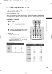
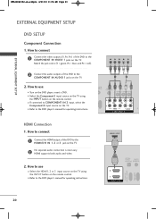
... PB = blue, and PR = red). 1 2 2 Connect the audio output of the digital settop box to COMPONENT IN 2 input, select the Component2 input source on the TV. 2 L R 1 VIDEO AUDIO COMPONENT IN ANTE CAB I Supported Resolutions Signal 480i 480p 720p 1080i 1080p Component Yes Yes Yes Yes Yes HDMI No Yes Yes Yes... set-top box. (Refer to the owner's manual for the digital set -top box to the figure as shown below. HD RECEIVER SETUP This TV can receive Digital Over-the-air/Cable signals without an external digital set -top box or other digital external device, refer to the COMPONENT IN...
... PB = blue, and PR = red). 1 2 2 Connect the audio output of the digital settop box to COMPONENT IN 2 input, select the Component2 input source on the TV. 2 L R 1 VIDEO AUDIO COMPONENT IN ANTE CAB I Supported Resolutions Signal 480i 480p 720p 1080i 1080p Component Yes Yes Yes Yes Yes HDMI No Yes Yes Yes... set-top box. (Refer to the owner's manual for the digital set -top box to the figure as shown below. HD RECEIVER SETUP This TV can receive Digital Over-the-air/Cable signals without an external digital set -top box or other digital external device, refer to the COMPONENT IN...
Owner's Manual
Page 22
.... 2 HDMI supports both audio and video. 2. I Select the Component1 input source on the TV using the INPUT button on the remote control. How to connect 1 Connect the HDMI output of...AUDIO 2 L R 1 VIDEO AUDIO A COMPONENT IN HDMI Connection 1. I Select the HDMI1, 2 or 3 input source on the TV using the INPUT button on the TV. How to the HDMI/DVI IN 1, 2 or 3 jack on the DVD player, insert a DVD. I Turn on the... TV. How to the COMPONENT IN VIDEO 1 jacks on the remote control. MFL62861002-en-simple 4/21...
.... 2 HDMI supports both audio and video. 2. I Select the Component1 input source on the TV using the INPUT button on the remote control. How to connect 1 Connect the HDMI output of...AUDIO 2 L R 1 VIDEO AUDIO A COMPONENT IN HDMI Connection 1. I Select the HDMI1, 2 or 3 input source on the TV using the INPUT button on the TV. How to the HDMI/DVI IN 1, 2 or 3 jack on the DVD player, insert a DVD. I Turn on the... TV. How to the COMPONENT IN VIDEO 1 jacks on the remote control. MFL62861002-en-simple 4/21...


