Owner's Manual (English)
Page 4
... Panel Controls 4 Back Panel Information 6 Stand Installation 9 Attaching the TV to a Desk 10 Swivel Stand 10 Attaching the TV to a Wall 11 Back Cover for PC Mode 29 USB In Setup 31 AV Output Setup 32 Digital Audio Output Setup 33 WATCHING TV / PROGRAMME CONTROL Remote Control Key Functions 34 Turning on the TV 36 Initializing Setup 36 Programme Selection 37 Volume Adjustment 37 On-Screen Menus Selection and Adjustment . . 38 Factory Reset 39 Model Info 39 Auto Programme Tuning 40 Manual Programme Tuning 42...
... Panel Controls 4 Back Panel Information 6 Stand Installation 9 Attaching the TV to a Desk 10 Swivel Stand 10 Attaching the TV to a Wall 11 Back Cover for PC Mode 29 USB In Setup 31 AV Output Setup 32 Digital Audio Output Setup 33 WATCHING TV / PROGRAMME CONTROL Remote Control Key Functions 34 Turning on the TV 36 Initializing Setup 36 Programme Selection 37 Volume Adjustment 37 On-Screen Menus Selection and Adjustment . . 38 Factory Reset 39 Model Info 39 Auto Programme Tuning 40 Manual Programme Tuning 42...

Owner's Manual (English)
Page 5
Speaker Sound Output Selection 84 Subtitle 85 TIME SETTING Clock Setting 86 Auto On/ Off Timer Setting 88 Sleep Timer Setting 89 Auto Shut-off Setting 90 PARENTAL CONTROL / RATINGS Set Password & Lock System 91 Programme Blocking 93 Parental Guidance 94 External Input Blocking 95 APPENDIX Troubleshooting 98 Maintenance 100 Product Specifications 101 Programming the Remote Control 104 IR Codes 107 External Control through RS-232C 109 Open Source License 115 TELETEXT Switch On/Off 96 Simple Text 96 TOP...
Speaker Sound Output Selection 84 Subtitle 85 TIME SETTING Clock Setting 86 Auto On/ Off Timer Setting 88 Sleep Timer Setting 89 Auto Shut-off Setting 90 PARENTAL CONTROL / RATINGS Set Password & Lock System 91 Programme Blocking 93 Parental Guidance 94 External Input Blocking 95 APPENDIX Troubleshooting 98 Maintenance 100 Product Specifications 101 Programming the Remote Control 104 IR Codes 107 External Control through RS-232C 109 Open Source License 115 TELETEXT Switch On/Off 96 Simple Text 96 TOP...

Owner's Manual (English)
Page 9
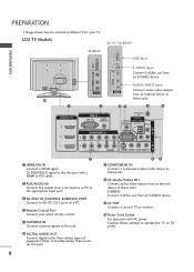
... second TV or monitor. (CONTROL & SERVICE) Connect your wired remote control. 10 Power Cord Socket 5 ANTENNA IN Connect antenna signals to these jacks. VIDEO AV IN 1 For operation with a HDMI to the appropriate input port. device to this port with AC power. Caution: Never attempt to the RS-232C port on DC power. Note: In standby mode, these jacks. 8 AV (Audio/Video) IN 1 2 RGB/AUDIO IN Connect audio/video output from an external Connect the output from a set top box or PC to DVI cable. RGB IN HDMI/DVI...
... second TV or monitor. (CONTROL & SERVICE) Connect your wired remote control. 10 Power Cord Socket 5 ANTENNA IN Connect antenna signals to these jacks. VIDEO AV IN 1 For operation with a HDMI to the appropriate input port. device to this port with AC power. Caution: Never attempt to the RS-232C port on DC power. Note: In standby mode, these jacks. 8 AV (Audio/Video) IN 1 2 RGB/AUDIO IN Connect audio/video output from an external Connect the output from a set top box or PC to DVI cable. RGB IN HDMI/DVI...
Owner's Manual (English)
Page 10
... AUDIO R VIDEO L/MONO AUDIO R AUDIO/VIDEO Input Connect audio/video output AV IN 2 AV INAV2IN 2 AV IN 2 from a set top box or PC to these jacks. 10 1 2 34 5 6 AV OUT HDMI/DVI IN 3 2 1 RGB IN RGB (PC) AUDIO (RGB/DVI) COMPONENT IN ANTENNA IN REMOTE CONTROL IN DIGITAL AUDIO OUT OPTICAL VIDEO RS-232C IN (CONTROL & SERVICE) AUDIO VIDEO AUDIO S-VIDEO VIDEO (MONO) AUDIO AV IN 1 7 89 1 HDMI/DVI IN 7 COMPONENT IN Connect a HDMI signal. Never attemDIGpITtALto AUDIO OUT operate the TV on a PC. 9 AV OUT 4 Remote Control Port Connect a second TV or monitor...
... AUDIO R VIDEO L/MONO AUDIO R AUDIO/VIDEO Input Connect audio/video output AV IN 2 AV INAV2IN 2 AV IN 2 from a set top box or PC to these jacks. 10 1 2 34 5 6 AV OUT HDMI/DVI IN 3 2 1 RGB IN RGB (PC) AUDIO (RGB/DVI) COMPONENT IN ANTENNA IN REMOTE CONTROL IN DIGITAL AUDIO OUT OPTICAL VIDEO RS-232C IN (CONTROL & SERVICE) AUDIO VIDEO AUDIO S-VIDEO VIDEO (MONO) AUDIO AV IN 1 7 89 1 HDMI/DVI IN 7 COMPONENT IN Connect a HDMI signal. Never attemDIGpITtALto AUDIO OUT operate the TV on a PC. 9 AV OUT 4 Remote Control Port Connect a second TV or monitor...
Owner's Manual (English)
Page 20
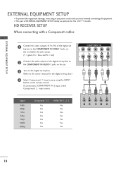
... owner's manual for the LCD TV models. I To prevent the equipment damage, never plug in any power cords until you have finished connecting all equipment. HD RECEIVER SETUP When connecting with a Component cables RGB IN RGB (PC) 1 Connect the video outputs (Y, PB, PR) of the digital set top box to the COMPONENT IN VIDEO 1 jacks on the set -top box.) 4 Select Component 1 input source using the INPUT button on the digital set-top box. (Refer to COMPONENT IN 2 input, select Component 2 input source...
... owner's manual for the LCD TV models. I To prevent the equipment damage, never plug in any power cords until you have finished connecting all equipment. HD RECEIVER SETUP When connecting with a Component cables RGB IN RGB (PC) 1 Connect the video outputs (Y, PB, PR) of the digital set top box to the COMPONENT IN VIDEO 1 jacks on the set -top box.) 4 Select Component 1 input source using the INPUT button on the digital set-top box. (Refer to COMPONENT IN 2 input, select Component 2 input source...

Owner's Manual (English)
Page 21
AUDIO 2 3 Turn on the digital set-top box. (Refer to the owner's manual for the digital set-top box.) 1 COMPONENT IN VIDEO AUDIO 4 Select HDMI1, HDMI2 or HDMI3 input source using the INPUT button on the set. To get the best picture quality, adjust the output resolution of the source device will be automatically set the output resolution appropriately. NOTE G If the digital set-top box supports Auto HDMI function, the output resolution of the source device to 1920x1080i/1080p. (32LB9D*, 42/50PB4D*: 1280x720p) 1 HDMI-DTV OUTPUT 19 HDMI/DVI IN RGB...
AUDIO 2 3 Turn on the digital set-top box. (Refer to the owner's manual for the digital set-top box.) 1 COMPONENT IN VIDEO AUDIO 4 Select HDMI1, HDMI2 or HDMI3 input source using the INPUT button on the set. To get the best picture quality, adjust the output resolution of the source device will be automatically set the output resolution appropriately. NOTE G If the digital set-top box supports Auto HDMI function, the output resolution of the source device to 1920x1080i/1080p. (32LB9D*, 42/50PB4D*: 1280x720p) 1 HDMI-DTV OUTPUT 19 HDMI/DVI IN RGB...

Owner's Manual (English)
Page 22
... REMOTE CONTROL IN DIGITAL AUDIO OUT OPTICAL VIDEO RS-232C IN (CONTROL & SERVICE) AUDIO VIDEO AUDIO S-VIDEO VIDEO (MONO) AUDIO 1 2 AV OUT AV IN 1 DVI-DTV OUTPUT L R 1 Connect the DVI output of the digital set-top box to the HDMI/DVI IN1, 2 or 3 jack on the set. 2 Connect the audio output of the digital set-top box to the AUDIO(RGB/DVI) jack on the set. 3 Turn on the digital set-top box. (Refer to the owner's manual for the digital set-top box.) 4 Select HDMI1, HDMI2 or HDMI3 input source with using the INPUT button on the remote control...
... REMOTE CONTROL IN DIGITAL AUDIO OUT OPTICAL VIDEO RS-232C IN (CONTROL & SERVICE) AUDIO VIDEO AUDIO S-VIDEO VIDEO (MONO) AUDIO 1 2 AV OUT AV IN 1 DVI-DTV OUTPUT L R 1 Connect the DVI output of the digital set-top box to the HDMI/DVI IN1, 2 or 3 jack on the set. 2 Connect the audio output of the digital set-top box to the AUDIO(RGB/DVI) jack on the set. 3 Turn on the digital set-top box. (Refer to the owner's manual for the digital set-top box.) 4 Select HDMI1, HDMI2 or HDMI3 input source with using the INPUT button on the remote control...

Owner's Manual (English)
Page 24
... input source using the INPUT button on the remote control. If connected to AV IN 2 input, select A V 2 input source.(Except 32LB9D*) 5 Refer to the DVD player's manual for operating instruc- NOTE G If the DVD supports Auto HDMI function, the DVD output resolution will be automatically set to set the output resolution appropriately. G If the DVD does not support Auto HDMI, you need to 1280x720p. VIDEO AUDIO 2 Connect the audio outputs of the DVD to the S-VIDEO input on the set. tions. To get the besRtGpBicINture quality, adjust the output resolution of HDMI/DVItIhNe DVD...
... input source using the INPUT button on the remote control. If connected to AV IN 2 input, select A V 2 input source.(Except 32LB9D*) 5 Refer to the DVD player's manual for operating instruc- NOTE G If the DVD supports Auto HDMI function, the DVD output resolution will be automatically set to set the output resolution appropriately. G If the DVD does not support Auto HDMI, you need to 1280x720p. VIDEO AUDIO 2 Connect the audio outputs of the DVD to the S-VIDEO input on the set. tions. To get the besRtGpBicINture quality, adjust the output resolution of HDMI/DVItIhNe DVD...

Owner's Manual (English)
Page 25
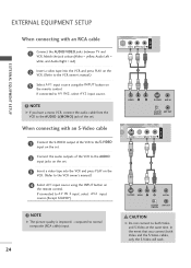
... and press PLAY on the screen. R HDMI/DVI IN RGB When connecting with an antenna C 2 EXTERNAL EQUIPMENT SETUP HDMI/DVI IN 2 1 (DVI) RGB IN RGB (PC) AUDIO (RGB/DVI) COMPONENT IN ANTENNA IN REMOTE CONTROL IN DIGITAL AUDIO OUT OPTICAL VIDEO RS-232C IN (CONTROL & SERVICE) AUDIO VIDEO AUDIO S-VIDEO VIDEO (MONO) AUDIO AV IN 1 AV OUT 1 ANT OUT S-VIDEO VIDEO L R ANT IN OUTPUT SWITCH 2 Wall Jack 1 (DVI) VI Antenna 1 Connect the RF antenna out socket of the VCR to the ANTENNA I N socket on the set. 2 Connect the antenna cable to the...
... and press PLAY on the screen. R HDMI/DVI IN RGB When connecting with an antenna C 2 EXTERNAL EQUIPMENT SETUP HDMI/DVI IN 2 1 (DVI) RGB IN RGB (PC) AUDIO (RGB/DVI) COMPONENT IN ANTENNA IN REMOTE CONTROL IN DIGITAL AUDIO OUT OPTICAL VIDEO RS-232C IN (CONTROL & SERVICE) AUDIO VIDEO AUDIO S-VIDEO VIDEO (MONO) AUDIO AV IN 1 AV OUT 1 ANT OUT S-VIDEO VIDEO L R ANT IN OUTPUT SWITCH 2 Wall Jack 1 (DVI) VI Antenna 1 Connect the RF antenna out socket of the VCR to the ANTENNA I N socket on the set. 2 Connect the antenna cable to the...
Owner's Manual (English)
Page 26
... to the VCR owner's manual.) 4 SeleCctOAMVPO1NinEpNuTtINsource using the INPUT button on the set . NOTE HDMI/DVI IN RGB IN RGB (PC) G If you connect both Video and S-Video at the same time. HDMI/DVI IN RGB IN RGB (PC) EXTERNAL EQUIPMENT SETUP COMPONENT IN 2 When connecting with an S-Video cable 1 (DVI) VIDEO AUDIO 1 Connect the S-VIDEO output of the VCR to the S-VIDEO input on 2 the remote control. VIDEO L R S-VIDEO DIGITAL AUDIO OUT ANT IN OUTPUT ANT OUT SWITCH AV IN 1 AUDIO S-VIDEO VIDEO (MONO) AUDIO 2 Connect the audio outputs of the...
... to the VCR owner's manual.) 4 SeleCctOAMVPO1NinEpNuTtINsource using the INPUT button on the set . NOTE HDMI/DVI IN RGB IN RGB (PC) G If you connect both Video and S-Video at the same time. HDMI/DVI IN RGB IN RGB (PC) EXTERNAL EQUIPMENT SETUP COMPONENT IN 2 When connecting with an S-Video cable 1 (DVI) VIDEO AUDIO 1 Connect the S-VIDEO output of the VCR to the S-VIDEO input on 2 the remote control. VIDEO L R S-VIDEO DIGITAL AUDIO OUT ANT IN OUTPUT ANT OUT SWITCH AV IN 1 AUDIO S-VIDEO VIDEO (MONO) AUDIO 2 Connect the audio outputs of the...

Owner's Manual (English)
Page 28
... graphic card. There may be changed, change the screen scanning rate for this purpose. If the refresh rate of the PC graphic card can not be noise associated with the resolution, vertical pattern, contrast or brightness in input option of the PC graphic card. RGB IN RGB (PC) AUDIO (RGB/DVI) COMPONENT IN ANTEN IN REMOTE CONTROL IN DIGITAL AUDIO OUT OPTICA RS-232C IN (CONTROL & SERVICE) VIDEO AUDIO S-VIDEO VIDEO (MON 1 2 ! RGB OUTPUT AUDIO...
... graphic card. There may be changed, change the screen scanning rate for this purpose. If the refresh rate of the PC graphic card can not be noise associated with the resolution, vertical pattern, contrast or brightness in input option of the PC graphic card. RGB IN RGB (PC) AUDIO (RGB/DVI) COMPONENT IN ANTEN IN REMOTE CONTROL IN DIGITAL AUDIO OUT OPTICA RS-232C IN (CONTROL & SERVICE) VIDEO AUDIO S-VIDEO VIDEO (MON 1 2 ! RGB OUTPUT AUDIO...

Owner's Manual (English)
Page 29
... IN (CONTROL & SERVICE) AUDIO VIDEO AUDIO S-VIDEO VIDEO (MONO) AUDIO 1 2 AV IN 1 DVI-PC OUTPUT L R 1 Connect the DVI output of the PC to the HDMI/DVI IN1, 2 or 3 jack on the set. (Use the HDMI to DVI cable) 2 Connect the PC audio output to 1920x1080, 60Hz. (42PB4D* : 1024x768p, 32LB9D*/50PB4D*: 1360x768p) 27 To get the best picture quality, adjust the PC graphics card's output resolution to the AUDIO (RGB/DVI) jack on the set. 3 Turn on the remote control. ! G If the PC does not support Auto DVI, you need to set...
... IN (CONTROL & SERVICE) AUDIO VIDEO AUDIO S-VIDEO VIDEO (MONO) AUDIO 1 2 AV IN 1 DVI-PC OUTPUT L R 1 Connect the DVI output of the PC to the HDMI/DVI IN1, 2 or 3 jack on the set. (Use the HDMI to DVI cable) 2 Connect the PC audio output to 1920x1080, 60Hz. (42PB4D* : 1024x768p, 32LB9D*/50PB4D*: 1360x768p) 27 To get the best picture quality, adjust the PC graphics card's output resolution to the AUDIO (RGB/DVI) jack on the set. 3 Turn on the remote control. ! G If the PC does not support Auto DVI, you need to set...

Owner's Manual (English)
Page 30
The fixed image may not work if a HDMI to DVI Cable is separate. G Avoid keeping a fixed image on the screen. G The synchronization input form for a long period of time. Supported Display Specifications (HDMI-DTV) Resolution Horizontal Vertical ...Depending on the graphics card, DOS mode may become permanently imprinted on the screen for Horizontal and Vertical frequencies is in use. EXTERNAL EQUIPMENT SETUP EXTERNAL EQUIPMENT SETUP Supported Display Specifications (RGB/HDMI-PC) Resolution Horizontal Vertical Frequency(kHz) Frequency(Hz...42PB4D* Except 50PB4D* !
The fixed image may not work if a HDMI to DVI Cable is separate. G Avoid keeping a fixed image on the screen. G The synchronization input form for a long period of time. Supported Display Specifications (HDMI-DTV) Resolution Horizontal Vertical ...Depending on the graphics card, DOS mode may become permanently imprinted on the screen for Horizontal and Vertical frequencies is in use. EXTERNAL EQUIPMENT SETUP EXTERNAL EQUIPMENT SETUP Supported Display Specifications (RGB/HDMI-PC) Resolution Horizontal Vertical Frequency(kHz) Frequency(Hz...42PB4D* Except 50PB4D* !
Owner's Manual (English)
Page 31
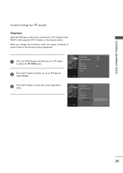
... Temperature XD Advanced Aspect Ratio Picture Reset Screen G Selection ( G or ) leads you change the resolution, select the proper resolution in present input to see the best picture appearance. 1 Press the MENU button and then use D or E button to select the PICTURE menu. 2 Press the G button and then use D or E button to select Screen. 3 Press the G button to enter the screen adjustment menu. When you to a PC Output, Select RGB-PC with using the INPUT button on the remote control.
... Temperature XD Advanced Aspect Ratio Picture Reset Screen G Selection ( G or ) leads you change the resolution, select the proper resolution in present input to see the best picture appearance. 1 Press the MENU button and then use D or E button to select the PICTURE menu. 2 Press the G button and then use D or E button to select Screen. 3 Press the G button to enter the screen adjustment menu. When you to a PC Output, Select RGB-PC with using the INPUT button on the remote control.

Owner's Manual (English)
Page 35
Off" in the AUDIO menu. REMOTE CONTROL IN DIGITAL AUDIO OUT OPTICAL VIDEO RS-232C IN (CONTROL & SERVICE) 1 AUDIO S-VIDEO VIDEO (MONO) AUDIO 2 ! AV OUT EXTERNAL EQUIPMENT SETUP AV IN 1 DIGITAL AUDIO OUTPUT SETUP Send the TV's audio to the TRGVB (DPCi)gital Audio (Optical) Output port. See the external audio equipment instruction manual for operation. CAUTION G Do not look into the optical output port. RGB IN HDMI/DVI IN 1 Connect one end of the optical cable to the digi- tal audio (optical) input on the audio equipment. 1 (DVI) VIDEO AUDIO 3 Set the "TV Speaker option -...
Off" in the AUDIO menu. REMOTE CONTROL IN DIGITAL AUDIO OUT OPTICAL VIDEO RS-232C IN (CONTROL & SERVICE) 1 AUDIO S-VIDEO VIDEO (MONO) AUDIO 2 ! AV OUT EXTERNAL EQUIPMENT SETUP AV IN 1 DIGITAL AUDIO OUTPUT SETUP Send the TV's audio to the TRGVB (DPCi)gital Audio (Optical) Output port. See the external audio equipment instruction manual for operation. CAUTION G Do not look into the optical output port. RGB IN HDMI/DVI IN 1 Connect one end of the optical cable to the digi- tal audio (optical) input on the audio equipment. 1 (DVI) VIDEO AUDIO 3 Set the "TV Speaker option -...

Owner's Manual (English)
Page 36
... SIZE ? It returns to TV. NUMBER button Selects a programme. POWER Switches the set of AV devices connected to the default settings brightness by changing mode source. VCR/DVD Control some video cassette recorders or DVD players control buttons ("RECORD" button is not available for DVD player). THUMBSTICK Adjusts menu settings. (Up/Down/Left Right) Selects menu item. PROGRAMME Select a programme. REVEAL INDEX I /II Selects the sound output or the audio mode. WATCHING TV /PROGRAMME CONTROL WATCHING TV/PROGRAMME CONTROL REMOTE CONTROL KEY FUNCTIONS When using the remote...
... SIZE ? It returns to TV. NUMBER button Selects a programme. POWER Switches the set of AV devices connected to the default settings brightness by changing mode source. VCR/DVD Control some video cassette recorders or DVD players control buttons ("RECORD" button is not available for DVD player). THUMBSTICK Adjusts menu settings. (Up/Down/Left Right) Selects menu item. PROGRAMME Select a programme. REVEAL INDEX I /II Selects the sound output or the audio mode. WATCHING TV /PROGRAMME CONTROL WATCHING TV/PROGRAMME CONTROL REMOTE CONTROL KEY FUNCTIONS When using the remote...
Owner's Manual (English)
Page 40
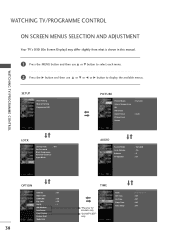
... each menu. 2 Press the G button and then use D or E or F or G button to display the available menus. SETUP Auto Tuning Manual Tuning Programme Edit PICTURE Picture Mode Colour Temperature XD Advanced Aspect Ratio Picture Reset Screen : Dynamic : Auto LOCK Lock System : Off Set Password Block Programme Parental Guidance Input Block AUDIO Sound Mode Auto Volume Balance TV Speaker : Standard : On : 0 : On 38 OPTION Subtitle Input Label SIMPLINK Key Lock Set ID ISM Method Low Power Front Display Factory Reset Model Info : Off : Off : Off : 1 TIME *Plasma TV models only...
... each menu. 2 Press the G button and then use D or E or F or G button to display the available menus. SETUP Auto Tuning Manual Tuning Programme Edit PICTURE Picture Mode Colour Temperature XD Advanced Aspect Ratio Picture Reset Screen : Dynamic : Auto LOCK Lock System : Off Set Password Block Programme Parental Guidance Input Block AUDIO Sound Mode Auto Volume Balance TV Speaker : Standard : On : 0 : On 38 OPTION Subtitle Input Label SIMPLINK Key Lock Set ID ISM Method Low Power Front Display Factory Reset Model Info : Off : Off : Off : 1 TIME *Plasma TV models only...
Owner's Manual (English)
Page 41
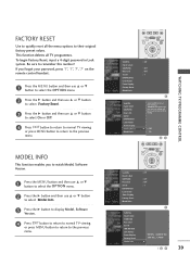
... TV viewing or press MENU button to return to their original factory preset values. To begin Factory Reset, input a 4-digit password in Lock system. WATCHING TV/PROGRAMME CONTROL MENU EXIT SUBTITLE MARK OK Subtitle Input Label SIMPLINK Key Lock Set ID ISM Method Low Power Front Display Factory Reset Model Info : Off : Off : Off : 1 Subtitle Input label SIMPLINK Key Lock Set ID ISM Method Low Power Front Display Factory Reset Model Info Selection(ON) resets all TV programmes. This function deletes all users settings. POWER FACTORY RESET Use...
... TV viewing or press MENU button to return to their original factory preset values. To begin Factory Reset, input a 4-digit password in Lock system. WATCHING TV/PROGRAMME CONTROL MENU EXIT SUBTITLE MARK OK Subtitle Input Label SIMPLINK Key Lock Set ID ISM Method Low Power Front Display Factory Reset Model Info : Off : Off : Off : 1 Subtitle Input label SIMPLINK Key Lock Set ID ISM Method Low Power Front Display Factory Reset Model Info Selection(ON) resets all TV programmes. This function deletes all users settings. POWER FACTORY RESET Use...
Owner's Manual (English)
Page 113
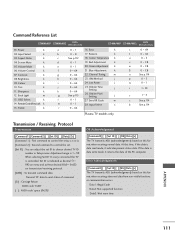
... receiving normal data. Transmit 'FF' data to choose desired TV ID number in Setup menu. Data1: Illegal Code Data2: Not supported function Data3: Wait more time APPENDIX 111 Command Reference List COMMAND1 COMMAND2 DATA (Hexadecimal) COMMAND1 COMMAND2 DATA (Hexadecimal) 01. Power k 02. Sharpness k 12. Treble k a 0~1 16. Red Adjustment k e 0~1 20. Channel Tuning m h 0 ~ 64 23. Aspect Ratio k 04. Back Light m 13. Volume Control k 07. Blue Adjustment k g 0 ~ 64 22. Orbiter Time k 0 ~ 64 Setting...
... receiving normal data. Transmit 'FF' data to choose desired TV ID number in Setup menu. Data1: Illegal Code Data2: Not supported function Data3: Wait more time APPENDIX 111 Command Reference List COMMAND1 COMMAND2 DATA (Hexadecimal) COMMAND1 COMMAND2 DATA (Hexadecimal) 01. Power k 02. Sharpness k 12. Treble k a 0~1 16. Red Adjustment k e 0~1 20. Channel Tuning m h 0 ~ 64 23. Aspect Ratio k 04. Back Light m 13. Volume Control k 07. Blue Adjustment k g 0 ~ 64 22. Orbiter Time k 0 ~ 64 Setting...

Owner's Manual (English)
Page 116
...][ ][OK/NG][Data][x] 27. Input Select(Command: x b) To select input source for all models. Blue adjustment(Command:$) To adjust blue in colour temperature. Low Power (Command2:q) To reduce the power consumption of the set. Orbiter Time Setting (Command2:r) To adjust orbiter operation time term. Acknowledgement [r][ ][Set ID][ ][OK/NG][Data][x] 26. Acknowledgement [c][ ][Set ID][ ][OK/NG][Data][x] 28. Transmission [x][b][ ][Set ID][ ][Data][Cr] Data 00 : Digital Data 41 : Component2 Data...
...][ ][OK/NG][Data][x] 27. Input Select(Command: x b) To select input source for all models. Blue adjustment(Command:$) To adjust blue in colour temperature. Low Power (Command2:q) To reduce the power consumption of the set. Orbiter Time Setting (Command2:r) To adjust orbiter operation time term. Acknowledgement [r][ ][Set ID][ ][OK/NG][Data][x] 26. Acknowledgement [c][ ][Set ID][ ][OK/NG][Data][x] 28. Transmission [x][b][ ][Set ID][ ][Data][Cr] Data 00 : Digital Data 41 : Component2 Data...


