

Owner's Manual
Page 1
Retain it for future reference. Record model number and serial number of the set . Refer to the label on the back cover and quote this manual carefully before operating your dealer when requiring service. ENGLISH LCD TV PLASMA TV OWNER'S MANUAL LCD TV MODELS 22/26LG1*** 32/37LG1*** 42/47LG1*** 22/26LG3*** 32/37LG3*** 42/47LG3*** 32LG5*** 37/42LG5*** 47/52LG5*** PLASMA TV MODELS 32PC5*** 42PG1*** 50PG1*** 42PG2*** 50PG2*** Please read this information. To your set .
Retain it for future reference. Record model number and serial number of the set . Refer to the label on the back cover and quote this manual carefully before operating your dealer when requiring service. ENGLISH LCD TV PLASMA TV OWNER'S MANUAL LCD TV MODELS 22/26LG1*** 32/37LG1*** 42/47LG1*** 22/26LG3*** 32/37LG3*** 42/47LG3*** 32LG5*** 37/42LG5*** 47/52LG5*** PLASMA TV MODELS 32PC5*** 42PG1*** 50PG1*** 42PG2*** 50PG2*** Please read this information. To your set .
Owner's Manual
Page 3
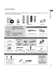
...*Lightly wipe any stains or fingerprints on the screen This feature is not available for all models. Owner's Manual Owner's manual Owner's Manual Batteries TV POWER INPUT STB DVD Q. MENU MENU OK RETURN PIP AV MODE FAV P MUTE 123 456 789 LIST 0 Q.VIEW or TIME SIZE UPDATE REVEAL...32/37/42LG1***, 26/32/37/42LG3***) or protection cover Screw for use excessive force. Do not use on the surface of the TV with your TV. ACCESSORIES ACCESSORIES Ensure that the following accessories are included with the polishing cloth. If an accessory is missing, please contact the dealer where...
...*Lightly wipe any stains or fingerprints on the screen This feature is not available for all models. Owner's Manual Owner's manual Owner's Manual Batteries TV POWER INPUT STB DVD Q. MENU MENU OK RETURN PIP AV MODE FAV P MUTE 123 456 789 LIST 0 Q.VIEW or TIME SIZE UPDATE REVEAL...32/37/42LG1***, 26/32/37/42LG3***) or protection cover Screw for use excessive force. Do not use on the surface of the TV with your TV. ACCESSORIES ACCESSORIES Ensure that the following accessories are included with the polishing cloth. If an accessory is missing, please contact the dealer where...
Owner's Manual
Page 4
... Please set it up carefully so the product does not fall over 13 Back Cover for PC Mode 36 WATCHING TV / PROGRAMME CONTROL Remote Control Key Functions 40 Turning on the TV 48 Programme Selection 48 Volume Adjustment 48 Quick Menu 49 On Screen Menus Selection and Adjustment ......50 2 Auto Programme Tuning...
... Please set it up carefully so the product does not fall over 13 Back Cover for PC Mode 36 WATCHING TV / PROGRAMME CONTROL Remote Control Key Functions 40 Turning on the TV 48 Programme Selection 48 Volume Adjustment 48 Quick Menu 49 On Screen Menus Selection and Adjustment ......50 2 Auto Programme Tuning...
Owner's Manual
Page 5
Stereo/Dual Reception 85 - Sound Mode 80 Sound Setting Adjustment - NICAM Reception 86 - User Mode 81 Balance 82 TV Speakers On/Off Setup 83 Selecting Audio Out 84 I/II - Speaker Sound Output Selection 86 On-Screen Menu Language Selection 87 TIME SETTING Clock Setup ...
Stereo/Dual Reception 85 - Sound Mode 80 Sound Setting Adjustment - NICAM Reception 86 - User Mode 81 Balance 82 TV Speakers On/Off Setup 83 Selecting Audio Out 84 I/II - Speaker Sound Output Selection 86 On-Screen Menu Language Selection 87 TIME SETTING Clock Setup ...
Owner's Manual
Page 6
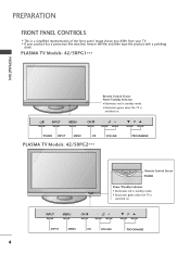
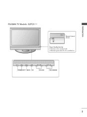
... Control Sensor Power/Standby Indicator • illuminates red in standby mode. • illuminates green when the TV is switched on. - + P POWER INPUT MENU OK PLASMA TV Models: 42/50PG2*** VOLUME PROGRAMME MENU OK - + P Remote Control Sensor POWER Power/Standby Indicator &#...8226; illuminates red in standby mode. • illuminates green when the TV is a simplified representation of the front panel. PREPARATION FRONT PANEL CONTROLS I If your TV. INPUT MENU OK - + P INPUT MENIUNPUT OK MENU- + OK INPUT MENU OK - + PVOLUME...
... Control Sensor Power/Standby Indicator • illuminates red in standby mode. • illuminates green when the TV is switched on. - + P POWER INPUT MENU OK PLASMA TV Models: 42/50PG2*** VOLUME PROGRAMME MENU OK - + P Remote Control Sensor POWER Power/Standby Indicator &#...8226; illuminates red in standby mode. • illuminates green when the TV is a simplified representation of the front panel. PREPARATION FRONT PANEL CONTROLS I If your TV. INPUT MENU OK - + P INPUT MENIUNPUT OK MENU- + OK INPUT MENU OK - + PVOLUME...
Owner's Manual
Page 7
PR INPUT MENU INPUT MENU OK OK VOL VOL PR POWER INPUT MENU OK VOLUME PR PROGRAMME 5 PREPARATION PLASMA TV Models: 32PC5*** Remote Control Sensor INPUT MENU OK VOL Power/Standby Indicator • illuminates red in standby mode. • illuminates green when the TV is switched on.
PR INPUT MENU INPUT MENU OK OK VOL VOL PR POWER INPUT MENU OK VOLUME PR PROGRAMME 5 PREPARATION PLASMA TV Models: 32PC5*** Remote Control Sensor INPUT MENU OK VOL Power/Standby Indicator • illuminates red in standby mode. • illuminates green when the TV is switched on.
Owner's Manual
Page 8
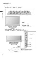
...INPUT OK MENU INPUT Intelligent Sensor Adjusts picture according to the surrounding conditions (Only 32/37/42/47/52LG5***) 6 PREPARATION LCD TV Models : 22LG1***, 22LG3*** INPUT MENU OK VOLUME PROGRAMME INPUT MENU OK VOL PR PREPARATION POWER Remote Control Sensor Power/Standby Indicator... • illuminates red in standby mode. • illuminates blue when the TV is switched on . Note: You can adjust Power Indicator in standby mode. • illuminates blue when the TV is switched on . POWER Remote Control Sensor Power/Standby Indicator • illuminates red...
...INPUT OK MENU INPUT Intelligent Sensor Adjusts picture according to the surrounding conditions (Only 32/37/42/47/52LG5***) 6 PREPARATION LCD TV Models : 22LG1***, 22LG3*** INPUT MENU OK VOLUME PROGRAMME INPUT MENU OK VOL PR PREPARATION POWER Remote Control Sensor Power/Standby Indicator... • illuminates red in standby mode. • illuminates blue when the TV is switched on . Note: You can adjust Power Indicator in standby mode. • illuminates blue when the TV is switched on . POWER Remote Control Sensor Power/Standby Indicator • illuminates red...
Owner's Manual
Page 9
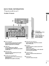
Audio/Video Input Connect audio/video output from an external device to these jacks. 6 AV Output Connect second TV or monitor to the AV OUT socket on an AC power. PLASMA TV Models PREPARATION 1 2 3 4 HDMI/DVI IN 1 HDMI IN 2 AV VIDEO RS-232C IN (CONTROL) RGB(PC) AUDIO AUDIO (RGB...RGB IN ANTENNA IN 8 S-Video Input Connect S-Video out from your surround sound system. 7 Component Input Connect a component video/audio device to operate the TV on the Specifications page. Or DVI(VIDEO)signal to HDMI/DVI port with DVI to HDMI cable. 3 RGB/Audio Input Connect the monitor output from...
Audio/Video Input Connect audio/video output from an external device to these jacks. 6 AV Output Connect second TV or monitor to the AV OUT socket on an AC power. PLASMA TV Models PREPARATION 1 2 3 4 HDMI/DVI IN 1 HDMI IN 2 AV VIDEO RS-232C IN (CONTROL) RGB(PC) AUDIO AUDIO (RGB...RGB IN ANTENNA IN 8 S-Video Input Connect S-Video out from your surround sound system. 7 Component Input Connect a component video/audio device to operate the TV on the Specifications page. Or DVI(VIDEO)signal to HDMI/DVI port with DVI to HDMI cable. 3 RGB/Audio Input Connect the monitor output from...
Owner's Manual
Page 10
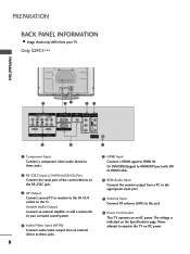
...a PC to the appropriate input port. 7 Antenna Input Connect RF antenna (UHF) to this jack. 8 Power Cord Socket This TV operates on DC power. 8 Or DVI(VIDEO)signal to HDMI/DVI port with DVI to HDMI cable. 6 RGB/Audio Input Connect ... devices to the RS-232C jack. 3 AV Output Connect second TV or monitor to operate the TV on an AC power. Never attempt to the AV OUT socket on the TV. The voltage is indicated on the Specifications page. Variable Audio Output... HDM 1 Component Input Connect a component video/audio device to these jacks. 5 HDMI Input Connect a HDMI signal to your TV.
...a PC to the appropriate input port. 7 Antenna Input Connect RF antenna (UHF) to this jack. 8 Power Cord Socket This TV operates on DC power. 8 Or DVI(VIDEO)signal to HDMI/DVI port with DVI to HDMI cable. 6 RGB/Audio Input Connect ... devices to the RS-232C jack. 3 AV Output Connect second TV or monitor to operate the TV on an AC power. Never attempt to the AV OUT socket on the TV. The voltage is indicated on the Specifications page. Variable Audio Output... HDM 1 Component Input Connect a component video/audio device to these jacks. 5 HDMI Input Connect a HDMI signal to your TV.
Owner's Manual
Page 11
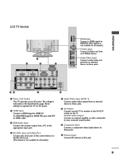
... IN 1) Connect audio/video output from an external device to these jacks. 6 AV Output Connect second TV or monitor to the AV OUT socket on an AC power. Never attempt to operate the TV on the Specifications page. Variable Audio Output Connect an external amplifier or add a subwoofer to your surround...the control devices to the RS-232C jack. (This feature is not available for all models.) 8 Antenna Input Connect RF antenna to this jack. 9 LCD TV Models AV AV RGB IN RGB IN 3 PREPARATION HDMI Input Connect a HDMI signal to HDMI IN. (This feature is not available for all models.) S-...
... IN 1) Connect audio/video output from an external device to these jacks. 6 AV Output Connect second TV or monitor to the AV OUT socket on an AC power. Never attempt to operate the TV on the Specifications page. Variable Audio Output Connect an external amplifier or add a subwoofer to your surround...the control devices to the RS-232C jack. (This feature is not available for all models.) 8 Antenna Input Connect RF antenna to this jack. 9 LCD TV Models AV AV RGB IN RGB IN 3 PREPARATION HDMI Input Connect a HDMI signal to HDMI IN. (This feature is not available for all models.) S-...

Owner's Manual
Page 12
... external device to these jacks. 7 Component Input Connect a component video/audio device to these jacks. 8 S-Video Input Connect S-Video out from your TV. The voltage is indicated on an AC power. Only 22LG1***, 22LG3*** PREPARATION 1 2 3 4 HDMI/DVI IN RGB (PC) IN AUDIO (RGB... S-VIDEO H/P RS-232C IN (CONTROL&SERVICE) LR Y PB PR L R VIDEO AUDIO COMPONENT IN 5 6 7 89 1 Power Cord Socket This TV operates on the Specifications page. PREPARATION BACK PANEL INFORMATION A Image shown may differ from an S-VIDEO device. 9 Headphone Input 4 Antenna Input Connect RF antenna...
... external device to these jacks. 7 Component Input Connect a component video/audio device to these jacks. 8 S-Video Input Connect S-Video out from your TV. The voltage is indicated on an AC power. Only 22LG1***, 22LG3*** PREPARATION 1 2 3 4 HDMI/DVI IN RGB (PC) IN AUDIO (RGB... S-VIDEO H/P RS-232C IN (CONTROL&SERVICE) LR Y PB PR L R VIDEO AUDIO COMPONENT IN 5 6 7 89 1 Power Cord Socket This TV operates on the Specifications page. PREPARATION BACK PANEL INFORMATION A Image shown may differ from an S-VIDEO device. 9 Headphone Input 4 Antenna Input Connect RF antenna...
Owner's Manual
Page 13
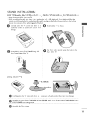
...shown. 2 Assemble the parts of the Stand Body with the Cover Base of the TV. 4 Fix the 4 bolts securely using the holes in the back of the TV. (Only 22LG3***) Stand Body Cover Base 1 Carefully place the TV screen side down on a cushioned surface to protect the screen from damage. 2 ... boltcan deviate from abrasion of the tightening part of the bolt. 1 Carefully place the TV screen side down on a cushioned surface to protect the screen from damage. 3 Assemble the TV as shown. 11 PREPARATION STAND INSTALLATION LCD TV Models: 26/32/37/42LG1***, 26/32/37/42LG3***, 32/37/42LG5*** I Image...
...shown. 2 Assemble the parts of the Stand Body with the Cover Base of the TV. 4 Fix the 4 bolts securely using the holes in the back of the TV. (Only 22LG3***) Stand Body Cover Base 1 Carefully place the TV screen side down on a cushioned surface to protect the screen from damage. 2 ... boltcan deviate from abrasion of the tightening part of the bolt. 1 Carefully place the TV screen side down on a cushioned surface to protect the screen from damage. 3 Assemble the TV as shown. 11 PREPARATION STAND INSTALLATION LCD TV Models: 26/32/37/42LG1***, 26/32/37/42LG3***, 32/37/42LG5*** I Image...

Owner's Manual
Page 14
..., potentially causing injury or damaging the product. Tipping, shaking, or rocking the machine may differ from your TV I Image shown may cause injury. 12 PREPARATION PREPARATION STAND INSTALLATION PLASMA TV Models (Only 42PG1***, 42PG2***, 32PC5***) I When assembling the desk type stand, check whether the bolt is...abrasion of the tightening part of the bolt. 1 Carefully place the TV screen side down on a cushioned surface to protect the screen from damage. WARNING G To prevent TV from falling over, the TV should be securely attached to desk so it cannot be attached to the...
..., potentially causing injury or damaging the product. Tipping, shaking, or rocking the machine may differ from your TV I Image shown may cause injury. 12 PREPARATION PREPARATION STAND INSTALLATION PLASMA TV Models (Only 42PG1***, 42PG2***, 32PC5***) I When assembling the desk type stand, check whether the bolt is...abrasion of the tightening part of the bolt. 1 Carefully place the TV screen side down on a cushioned surface to protect the screen from damage. WARNING G To prevent TV from falling over, the TV should be securely attached to desk so it cannot be attached to the...

Owner's Manual
Page 15
... the upper holes. 2 Secure the wall brackets with bolts to the wall as shown in the picture. (If your TV has bolts in the eyebolts, loosen then bolts.) * Insert the eye-bolts or TV brackets/bolts and tighten them securely in position. ! G Use a platform or cabinet string and large enough to the... wall, avoiding the possibility of it falling forwards if pulled. This will also prevent the TV from falling forward and causing injury. Secure the cord in such a way that children do not climb or hang from the...
... the upper holes. 2 Secure the wall brackets with bolts to the wall as shown in the picture. (If your TV has bolts in the eyebolts, loosen then bolts.) * Insert the eye-bolts or TV brackets/bolts and tighten them securely in position. ! G Use a platform or cabinet string and large enough to the... wall, avoiding the possibility of it falling forwards if pulled. This will also prevent the TV from falling forward and causing injury. Secure the cord in such a way that children do not climb or hang from the...
Owner's Manual
Page 16
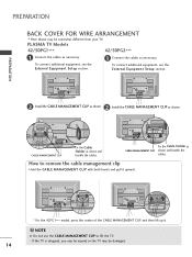
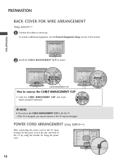
PREPARATION PREPARATION BACK COVER FOR WIRE ARRANGEMENT I Here shown may be somewhat different from your TV. How to lift the TV. - If the TV is dropped, you may be injured or the TV may be damaged. 14 PLASMA TV Models 42/50PG1*** 42/50PG2*** 1 Connect the cables as necessary. 1 Connect the cables as CABLE MANAGEMENT CLIP...
PREPARATION PREPARATION BACK COVER FOR WIRE ARRANGEMENT I Here shown may be somewhat different from your TV. How to lift the TV. - If the TV is dropped, you may be injured or the TV may be damaged. 14 PLASMA TV Models 42/50PG1*** 42/50PG2*** 1 Connect the cables as necessary. 1 Connect the cables as CABLE MANAGEMENT CLIP...
Owner's Manual
Page 17
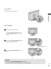
CABLE MANAGEMENT CLIP ! Only 32PC5*** Arrange the cables as necessary. NOTE G Do not use the CABLE MANAGEMENT CLIP to lift the TV. - If the TV is dropped, you may be injured or the TV may be damaged. 15 PREPARATION LCD TV Models 1 Connect the cables as shown picture. To connect additional equipment, see the External Equipment Setup section of the manual. 2 Open the CABLE MANAGEMENT CLIP as shown and manage the cables. 3 Fit the CABLE MANAGEMENT CLIP as shown.
CABLE MANAGEMENT CLIP ! Only 32PC5*** Arrange the cables as necessary. NOTE G Do not use the CABLE MANAGEMENT CLIP to lift the TV. - If the TV is dropped, you may be injured or the TV may be damaged. 15 PREPARATION LCD TV Models 1 Connect the cables as shown picture. To connect additional equipment, see the External Equipment Setup section of the manual. 2 Open the CABLE MANAGEMENT CLIP as shown and manage the cables. 3 Fit the CABLE MANAGEMENT CLIP as shown.
Owner's Manual
Page 18
...power cord at the rear side Hole of the manual. 2 Install the CABLE MANAGEMENT CLIP as necessary. CABLE MANAGEMENT CLIP How to lift the TV. - PREPARATION PREPARATION BACK COVER FOR WIRE ARRANGEMENT Only 22LG3*** 1 Connect the cables as shown. To connect additional equipment, see the External Equipment... Setup section of the TV by using the bracket for fixing the power cord. 16 NOTE G Do not use the CABLE MANAGEMENT CLIP to remove the CABLE MANAGEMENT ...
...power cord at the rear side Hole of the manual. 2 Install the CABLE MANAGEMENT CLIP as necessary. CABLE MANAGEMENT CLIP How to lift the TV. - PREPARATION PREPARATION BACK COVER FOR WIRE ARRANGEMENT Only 22LG3*** 1 Connect the cables as shown. To connect additional equipment, see the External Equipment... Setup section of the TV by using the bracket for fixing the power cord. 16 NOTE G Do not use the CABLE MANAGEMENT CLIP to remove the CABLE MANAGEMENT ...
Owner's Manual
Page 19
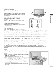
... placed in various ways for long periods of time. The Kensington Security System is turned on the monitor's performance. If the TV feels cold to the user's guide provided with the Kensington Security System. Doing so may be a small "flicker" when when it...), fix it for maximum comfort. This is normal, there is equipped with TV. After installing the TV, you install the TV to any unnecessary vibration, moisture, dust or heat. b. KENSINGTON SECURITY SYSTEM (Only 22LG1***, 22LG3***) The TV is nothing wrong with a Kensington Security System connector on the screen, appearing ...
... placed in various ways for long periods of time. The Kensington Security System is turned on the monitor's performance. If the TV feels cold to the user's guide provided with the Kensington Security System. Doing so may be a small "flicker" when when it...), fix it for maximum comfort. This is normal, there is equipped with TV. After installing the TV, you install the TV to any unnecessary vibration, moisture, dust or heat. b. KENSINGTON SECURITY SYSTEM (Only 22LG1***, 22LG3***) The TV is nothing wrong with a Kensington Security System connector on the screen, appearing ...
Owner's Manual
Page 20
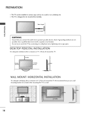
... install a separate circuit breaker. We recommend that you use a wall mounting bracket of 4" (10cm) all around the TV. I The TV can be mounted horizontally. DESKTOP PEDESTAL INSTALLATION For adequate ventilation allow a clearance of 4" (10cm) all around the... TV . 4 inches 4 inches 4 inches 4 inches WALL MOUNT: HORIZONTAL INSTALLATION For adequate ventilation allow a clearance of LG brand when mounting the TV to prevent possible electric shock. PREPARATION PREPARATION I The TV is designed to telephone wires, lightening rods or gas ...
... install a separate circuit breaker. We recommend that you use a wall mounting bracket of 4" (10cm) all around the TV. I The TV can be mounted horizontally. DESKTOP PEDESTAL INSTALLATION For adequate ventilation allow a clearance of 4" (10cm) all around the... TV . 4 inches 4 inches 4 inches 4 inches WALL MOUNT: HORIZONTAL INSTALLATION For adequate ventilation allow a clearance of LG brand when mounting the TV to prevent possible electric shock. PREPARATION PREPARATION I The TV is designed to telephone wires, lightening rods or gas ...
Owner's Manual
Page 21
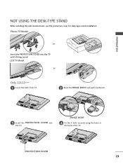
Plasma TV Models or Insert the PROTECTION COVER into the TV. PROTECTION COVER 19 PREPARATION NOT USING THE DESK-TYPE STAND When installing the wall-mounted unit, use the protection cover for desk-type stand installation. HINGE BODY 4 Fix the 4 bolts securely using the holes in the back of the TV. LCD TV Model or Only 22LG3*** 1 Loose the bolts from TV. 2 Bend the HINGE BODY and pull it backward. 3 Insert the PROTECTION COVER into the TV until clicking sound.
Plasma TV Models or Insert the PROTECTION COVER into the TV. PROTECTION COVER 19 PREPARATION NOT USING THE DESK-TYPE STAND When installing the wall-mounted unit, use the protection cover for desk-type stand installation. HINGE BODY 4 Fix the 4 bolts securely using the holes in the back of the TV. LCD TV Model or Only 22LG3*** 1 Loose the bolts from TV. 2 Bend the HINGE BODY and pull it backward. 3 Insert the PROTECTION COVER into the TV until clicking sound.


