Owner's Manual (English)
Page 3
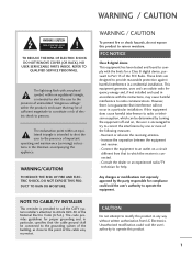
.... NO USER SERVICEABLE PARTS INSIDE. However, there is encouraged to try to the point of the following measures: - Increase the separation between the equipment and receiver. - Any changes or modifications not expressly approved by turning the equipment off and on a circuit different from LG Electronics. NOTE TO CABLE/TV INSTALLER This reminder is connected. - Reorient or relocate the receiving antenna...
.... NO USER SERVICEABLE PARTS INSIDE. However, there is encouraged to try to the point of the following measures: - Increase the separation between the equipment and receiver. - Any changes or modifications not expressly approved by turning the equipment off and on a circuit different from LG Electronics. NOTE TO CABLE/TV INSTALLER This reminder is connected. - Reorient or relocate the receiving antenna...
Owner's Manual (English)
Page 6
...Preset Sound Settings( Sound Mode 65 Sound Setting Adjustment - Channel Editing 42 Input List 43 SimpLink 44 Input Label 46 4 MEDIAHOST MEDIAHOST Entry Modes 47 Photo List 48 Music List 52 PICTURE CONTROL Picture Size (Aspect Ratio) Control 54 Preset Picture Settings - Preset 56 Manual Picture Adjustment - Picture Mode - Picture Mode - User Mode 66 Balance 68 Stereo / SAP Broadcast Setup 69 TV Speakers On/ Off Setup 70 Audio Language 71 On-Screen Menus Language Selection 72 Caption Mode - Analog Broadcasting System Captions . . . . 73 - Color Tone - Picture...
...Preset Sound Settings( Sound Mode 65 Sound Setting Adjustment - Channel Editing 42 Input List 43 SimpLink 44 Input Label 46 4 MEDIAHOST MEDIAHOST Entry Modes 47 Photo List 48 Music List 52 PICTURE CONTROL Picture Size (Aspect Ratio) Control 54 Preset Picture Settings - Preset 56 Manual Picture Adjustment - Picture Mode - Picture Mode - User Mode 66 Balance 68 Stereo / SAP Broadcast Setup 69 TV Speakers On/ Off Setup 70 Audio Language 71 On-Screen Menus Language Selection 72 Caption Mode - Analog Broadcasting System Captions . . . . 73 - Color Tone - Picture...

Owner's Manual (English)
Page 11
Remote Control Sensor Power/Standby Indicator • illuminates red in standby mode. • illuminates green when the set is switched on. 9 PREPARATION 37/42/47/52LB5D CH VOL ENTER MENU INPUT /I CHANNEL (E,D) Buttons VOLUME (F,G) Buttons ENTER Button MENU Button INPUT Button POWER Button Intelligent Eye Adjusts picture according to the surrounding conditions.
Remote Control Sensor Power/Standby Indicator • illuminates red in standby mode. • illuminates green when the set is switched on. 9 PREPARATION 37/42/47/52LB5D CH VOL ENTER MENU INPUT /I CHANNEL (E,D) Buttons VOLUME (F,G) Buttons ENTER Button MENU Button INPUT Button POWER Button Intelligent Eye Adjusts picture according to the surrounding conditions.
Owner's Manual (English)
Page 20
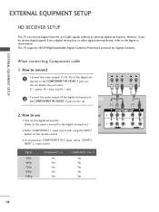
... jack colors (Y = green, PB = blue, and PR = red). 2 Connect the audio output of the digital set -top box. I Select COMPONENT 1 input source with using the INPUT button on the set. EXTERNAL EQUIPMENT SETUP EXTERNAL EQUIPMENT SETUP HD RECEIVER SETUP This TV can receive Digital Over-the-air/Cable signals without an external digital set top box to the COMPONENT IN VIDEO 1 jacks on the remote control. This TV supports HDCP (High-bandwidth Digital Contents Protection) protocol for the digital set-top bo(xDV.)I) I If connected to COMPONENT IN 2 input, select COMPONENT 2 input...
... jack colors (Y = green, PB = blue, and PR = red). 2 Connect the audio output of the digital set -top box. I Select COMPONENT 1 input source with using the INPUT button on the set. EXTERNAL EQUIPMENT SETUP EXTERNAL EQUIPMENT SETUP HD RECEIVER SETUP This TV can receive Digital Over-the-air/Cable signals without an external digital set top box to the COMPONENT IN VIDEO 1 jacks on the remote control. This TV supports HDCP (High-bandwidth Digital Contents Protection) protocol for the digital set-top bo(xDV.)I) I If connected to COMPONENT IN 2 input, select COMPONENT 2 input...
Owner's Manual (English)
Page 21
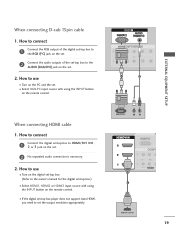
...the set. 2 Connect the audio outputs of the set-top box to the owner's manual for the digital set . 2 No separated audio connection is necessary. 2. RGB 1 2 When connecting HDMI cable 1. EXTERNAL EQUIPMENT SETUP When connecting D-sub 15pin cable 1. RGB OUTPUT L R (DVI) 1 HDMI-DTV OUTPUT 19 How to use I Turn on the digital set-top box. (Refer to the AUDIO (RGB/DVI) jack on the set -top box.) I Select RGB-PC input source with using the INPUT button on the remote control. I Select HDMI1, HDMI2 or HDMI3 input source with using the INPUT button on the remote control...
...the set. 2 Connect the audio outputs of the set-top box to the owner's manual for the digital set . 2 No separated audio connection is necessary. 2. RGB 1 2 When connecting HDMI cable 1. EXTERNAL EQUIPMENT SETUP When connecting D-sub 15pin cable 1. RGB OUTPUT L R (DVI) 1 HDMI-DTV OUTPUT 19 How to use I Turn on the digital set-top box. (Refer to the AUDIO (RGB/DVI) jack on the set -top box.) I Select RGB-PC input source with using the INPUT button on the remote control. I Select HDMI1, HDMI2 or HDMI3 input source with using the INPUT button on the remote control...
Owner's Manual (English)
Page 22
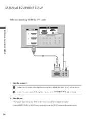
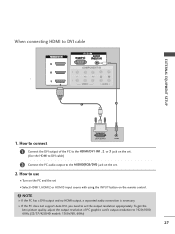
EXTERNAL EQUIPMENT SETUP When connecting HDMI to the owner's manual for the digital set-top box.) I Turn on the digital set . 2. How to use I Select HDMI1, HDMI2 or HDMI3 input source with using the INPUT button on the set -top box. (Refer to DVI cable RGB 3 EXTERNAL EQUIPMENT SETUP 2 1 DVI-DTV OUTPUT L R 1. How to connect 1 Connect the DVI output of the digital set-top box to the HDMI/DVI IN1, 2 or 3 jack on the set. 2 Connect the audio output of the digital set-top box to the AUDIO(RGB/DVI) jack on the remote control. 20
EXTERNAL EQUIPMENT SETUP When connecting HDMI to the owner's manual for the digital set-top box.) I Turn on the digital set . 2. How to use I Select HDMI1, HDMI2 or HDMI3 input source with using the INPUT button on the set -top box. (Refer to DVI cable RGB 3 EXTERNAL EQUIPMENT SETUP 2 1 DVI-DTV OUTPUT L R 1. How to connect 1 Connect the DVI output of the digital set-top box to the HDMI/DVI IN1, 2 or 3 jack on the set. 2 Connect the audio output of the digital set-top box to the AUDIO(RGB/DVI) jack on the remote control. 20
Owner's Manual (English)
Page 23
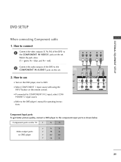
... better picture quality, connect a DVD player to the COMPONENT IN AUDIO1 jacks on the remote control. Component ports on the TV Y PB PR Video output ports on the set . 2. How to the DVD player's manual for operating instruc- I Refer to use I Select COMPONENT 1 input source with using the INPUT button on the set . tions. EXTERNAL EQUIPMENT SETUP DVD SETUP When connecting Component cable 1. I If connected to the COMPONENT IN VIDEO1 jacks on DVD player Y PB PR Y Pb Pr Y B-Y R-Y Y Cb Cr 21 Match the jack colors (Y = green, PB = blue, and PR = red...
... better picture quality, connect a DVD player to the COMPONENT IN AUDIO1 jacks on the remote control. Component ports on the TV Y PB PR Video output ports on the set . 2. How to the DVD player's manual for operating instruc- I Refer to use I Select COMPONENT 1 input source with using the INPUT button on the set . tions. EXTERNAL EQUIPMENT SETUP DVD SETUP When connecting Component cable 1. I If connected to the COMPONENT IN VIDEO1 jacks on DVD player Y PB PR Y Pb Pr Y B-Y R-Y Y Cb Cr 21 Match the jack colors (Y = green, PB = blue, and PR = red...
Owner's Manual (English)
Page 24
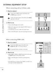
... control. How to connect 1 Connect the S-VIDEO output of the DVD to the S-VIDEO input on the set. 2 Connect the audio outputs of the DVD to the HDMI/DVI IN1, 2 or 3 jack on the set. 2 No separated audio connection is necessary. 2. I Turn on the set the output resolution appropriately. 22 1 HDMI-DVD OUTPUT How to connect 1 Connect the HDMI output of the DVD to set . 2. I If the DVD does not support Auto HDMI, you need to the AUDIO input jacks on the DVD player, insert a DVD. How to the DVD player's manual for operating instructions. S-VIDEO AUDIO L R 1 2 EXTERNAL...
... control. How to connect 1 Connect the S-VIDEO output of the DVD to the S-VIDEO input on the set. 2 Connect the audio outputs of the DVD to the HDMI/DVI IN1, 2 or 3 jack on the set. 2 No separated audio connection is necessary. 2. I Turn on the set the output resolution appropriately. 22 1 HDMI-DVD OUTPUT How to connect 1 Connect the HDMI output of the DVD to set . 2. I If the DVD does not support Auto HDMI, you need to the AUDIO input jacks on the DVD player, insert a DVD. How to the DVD player's manual for operating instructions. S-VIDEO AUDIO L R 1 2 EXTERNAL...
Owner's Manual (English)
Page 25
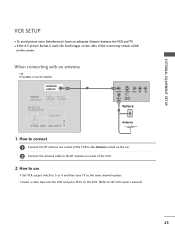
... channel number. the fixed images on the sides of the screen may remain visible on the set. 2 Connect the antenna cable to use I If the 4:3 picture format is used; How to the RF antenna in socket of the VCR to the VCR owner's manual.) 23 When connecting with an antenna i.e) 37/42LB4D, 37/42/47/52LB5D ANTENNA/ CABLE IN 1 ANT OUT S-VIDEO VIDEO L R ANT IN OUTPUT SWITCH Wall Jack 2 Antenna 1. How to connect 1 Connect the RF antenna out socket of the VCR. 2. I Insert a video...
... channel number. the fixed images on the sides of the screen may remain visible on the set. 2 Connect the antenna cable to use I If the 4:3 picture format is used; How to the RF antenna in socket of the VCR to the VCR owner's manual.) 23 When connecting with an antenna i.e) 37/42LB4D, 37/42/47/52LB5D ANTENNA/ CABLE IN 1 ANT OUT S-VIDEO VIDEO L R ANT IN OUTPUT SWITCH Wall Jack 2 Antenna 1. How to connect 1 Connect the RF antenna out socket of the VCR. 2. I Insert a video...
Owner's Manual (English)
Page 29
... the set. (Use the HDMI to DVI cable) 2 Connect the PC audio output to the AUDIO(RGB/DVI) jack on the remote control. NOTE G If the PC has a DVI output and no HDMI output, a separated audio connection is necessary. G If the PC does not support Auto DVI, you need to 1920x1080, 60Hz.(32/37/42LB4D models: 1360x768, 60Hz) 27 How to connect DVI-PC OUTPUT AUDIO 1 Connect the DVI output of PC graphics card's output resolution to set . 2. How to DVI cable RGB EXTERNAL EQUIPMENT SETUP 1 2 1. When connecting HDMI to use I Turn...
... the set. (Use the HDMI to DVI cable) 2 Connect the PC audio output to the AUDIO(RGB/DVI) jack on the remote control. NOTE G If the PC has a DVI output and no HDMI output, a separated audio connection is necessary. G If the PC does not support Auto DVI, you need to 1920x1080, 60Hz.(32/37/42LB4D models: 1360x768, 60Hz) 27 How to connect DVI-PC OUTPUT AUDIO 1 Connect the DVI output of PC graphics card's output resolution to set . 2. How to DVI cable RGB EXTERNAL EQUIPMENT SETUP 1 2 1. When connecting HDMI to use I Turn...

Owner's Manual (English)
Page 30
... another resolution, change the PC graphic card or consult the manufacturer of the PC graphic card. EXTERNAL EQUIPMENT SETUP 28 If the refresh rate of time. G Avoid keeping a fixed image on the screen for Horizontal and Vertical frequencies is separate. EXTERNAL EQUIPMENT SETUP NOTES G Depending on the graphics card, DOS mode may not work if a HDMI to DVI Cable is in PC mode. G The synchronization input form...
... another resolution, change the PC graphic card or consult the manufacturer of the PC graphic card. EXTERNAL EQUIPMENT SETUP 28 If the refresh rate of time. G Avoid keeping a fixed image on the screen for Horizontal and Vertical frequencies is separate. EXTERNAL EQUIPMENT SETUP NOTES G Depending on the graphics card, DOS mode may not work if a HDMI to DVI Cable is in PC mode. G The synchronization input form...
Owner's Manual (English)
Page 37
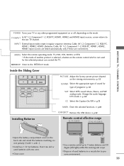
... TV channel. I Use a remote control up to preserve environment. 35 DAY + I Close cover. G p. 69 CC Select the Caption On/Off. G p.49 USB EJECT Remove the USB device. Don't mix old or used batteries in regular sequence: Antenna, Cable, AV1-2, Component 1-2, RGB-PC, HDMI1, HDMI2, HDMI3 (Antenna, Cable, AV 1-2, Component 1-2, RGB-PC, HDMI1, HDMI2, HDMI3 input sources are linked automatically, only if these are connected ). I Dispose of program.G p. 65 SAP Select MTS sound: Mono...
... TV channel. I Use a remote control up to preserve environment. 35 DAY + I Close cover. G p. 69 CC Select the Caption On/Off. G p.49 USB EJECT Remove the USB device. Don't mix old or used batteries in regular sequence: Antenna, Cable, AV1-2, Component 1-2, RGB-PC, HDMI1, HDMI2, HDMI3 (Antenna, Cable, AV 1-2, Component 1-2, RGB-PC, HDMI1, HDMI2, HDMI3 input sources are linked automatically, only if these are connected ). I Dispose of program.G p. 65 SAP Select MTS sound: Mono...

Owner's Manual (English)
Page 38
... the POWER, INPUT, TV INPUT, CH(D or E), Number (0~9) button on the remote control. 2 Select the viewing source by using the TV, press the POWER button on the remote control. MENU BRIGHT + TIMER RATIO SIMPLINK BACK PICTURE SOUND SAP CC MARK USB EJECT 36 TV INPUT INPUT STB MEDIA HOST BRIGHT - I This TV is programmed to remember which mode it was last set to, even if you intend to be away on the remote control. NOTE G If you turn the...
... the POWER, INPUT, TV INPUT, CH(D or E), Number (0~9) button on the remote control. 2 Select the viewing source by using the TV, press the POWER button on the remote control. MENU BRIGHT + TIMER RATIO SIMPLINK BACK PICTURE SOUND SAP CC MARK USB EJECT 36 TV INPUT INPUT STB MEDIA HOST BRIGHT - I This TV is programmed to remember which mode it was last set to, even if you intend to be away on the remote control. NOTE G If you turn the...
Owner's Manual (English)
Page 43
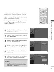
... access to Manual Tuning menu if the Lock System is different from the normal channel number shown in Channel Edit. MENU BRIGHT + TIMER RATIO SIMPLINK TV IN WATCHING TV / CHANNEL CONTROL 1 Press the MENU button and then use D or E button to select channel number you can view the on . DTV 2 Auto Tuning Manual Tuning Channel Edit Select channel type and RF-channel number. Auto Tuning Manual Tuning Channel Edit BACK PI PICTURE SOUND CC MARK USB EJECT Auto Tuning Manual Tuning Channel Edit G Select channel type and RF-channel number. BACK BACK PICTURE SOUND SAP...
... access to Manual Tuning menu if the Lock System is different from the normal channel number shown in Channel Edit. MENU BRIGHT + TIMER RATIO SIMPLINK TV IN WATCHING TV / CHANNEL CONTROL 1 Press the MENU button and then use D or E button to select channel number you can view the on . DTV 2 Auto Tuning Manual Tuning Channel Edit Select channel type and RF-channel number. Auto Tuning Manual Tuning Channel Edit BACK PI PICTURE SOUND CC MARK USB EJECT Auto Tuning Manual Tuning Channel Edit G Select channel type and RF-channel number. BACK BACK PICTURE SOUND SAP...
Owner's Manual (English)
Page 46
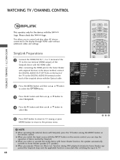
..., connect the DIGITAL AUDIO OUT OPTICAL on the back of the TV to the DIGITAL AUDIO IN terminal on the back of the simpLink device with the HDMI cable. TV INPUT STB MEDIA HOST BRIGHT - G When you can stop the operation of device worked by SimpLink. TIMER RATIO SIMPLINK Language Input label SimpLink Key Lock Caption Set ID : English : Off : Off : Off : 1 PICTURE SOUND BACK SAP CC MARK USB EJECT Language Input label...
..., connect the DIGITAL AUDIO OUT OPTICAL on the back of the TV to the DIGITAL AUDIO IN terminal on the back of the simpLink device with the HDMI cable. TV INPUT STB MEDIA HOST BRIGHT - G When you can stop the operation of device worked by SimpLink. TIMER RATIO SIMPLINK Language Input label SimpLink Key Lock Caption Set ID : English : Off : Off : Off : 1 PICTURE SOUND BACK SAP CC MARK USB EJECT Language Input label...

Owner's Manual (English)
Page 57
... User2 (your own settings). 2 Press the EXIT button to save and return to adjust Picture Mode. USBEJECT In the User 1, and User 2 modes only, user can also use the PICTURE menu to TV viewing. Picture Mode Color Temperature XD Advanced Aspect Ratio Picture Reset Screen : User1 : Cool : 16:9 Picture Mode G Color Temperature XD Advanced Aspect Ratio Picture Reset Screen Intelligent Eye Dynamic Standard Mild User 1 User 2 55 BACK BACK SAP USB EJECT CC Intelligent Eye, Dynamic, Standard, PICTURE SOUND MildCC Settings are preset for the best picture appearance.
... User2 (your own settings). 2 Press the EXIT button to save and return to adjust Picture Mode. USBEJECT In the User 1, and User 2 modes only, user can also use the PICTURE menu to TV viewing. Picture Mode Color Temperature XD Advanced Aspect Ratio Picture Reset Screen : User1 : Cool : 16:9 Picture Mode G Color Temperature XD Advanced Aspect Ratio Picture Reset Screen Intelligent Eye Dynamic Standard Mild User 1 User 2 55 BACK BACK SAP USB EJECT CC Intelligent Eye, Dynamic, Standard, PICTURE SOUND MildCC Settings are preset for the best picture appearance.
Owner's Manual (English)
Page 60
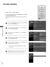
... select Red, Green, or Blue. 5 Press the G button and then use F or G button to the detailed setting screen. MENU BRIGHT + TIMER RATIO SIMPLINK Picture Mode : User1 Color Temperature : Cool XD Advanced Aspect Ratio : 16:9 Picture Reset Screen BACK PICTURE SOUND CC MARK USB EJECT Picture Mode Color Temperature XD Advanced Aspect Ratio Picture Reset Screen Cool Medium Warm User G Selection ( G or ) leads you to make appropriate adjustments. I The adjustment range of R e d, Green, or Blue is -20~ +20. 6 Press EXIT button to return to TV viewing...
... select Red, Green, or Blue. 5 Press the G button and then use F or G button to the detailed setting screen. MENU BRIGHT + TIMER RATIO SIMPLINK Picture Mode : User1 Color Temperature : Cool XD Advanced Aspect Ratio : 16:9 Picture Reset Screen BACK PICTURE SOUND CC MARK USB EJECT Picture Mode Color Temperature XD Advanced Aspect Ratio Picture Reset Screen Cool Medium Warm User G Selection ( G or ) leads you to make appropriate adjustments. I The adjustment range of R e d, Green, or Blue is -20~ +20. 6 Press EXIT button to return to TV viewing...
Owner's Manual (English)
Page 84
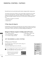
... theaters or direct-to be blocked. 2. Set ratings and categories to -video movies use the D or E button to select the LOCK menu. I TV-Y7 (Children 7 years older) PARENTAL CONTROL / RATING SET PASSWORD & LOCK SYSTEM TV INPUT TV INPUT Setting up your Password STB MEDIA HOST STB MEDIA HOST Set up with the initial password "0-0-0-0". PARENTAL CONTROL / RATINGS Parental Control can be used to block program viewing based on the ratings sent by choosing the type of the program and...
... theaters or direct-to be blocked. 2. Set ratings and categories to -video movies use the D or E button to select the LOCK menu. I TV-Y7 (Children 7 years older) PARENTAL CONTROL / RATING SET PASSWORD & LOCK SYSTEM TV INPUT TV INPUT Setting up your Password STB MEDIA HOST STB MEDIA HOST Set up with the initial password "0-0-0-0". PARENTAL CONTROL / RATINGS Parental Control can be used to block program viewing based on the ratings sent by choosing the type of the program and...

Owner's Manual (English)
Page 91
... the brightness of the antenna). 89 Poor reception on contact your antenna direction and/or location. I Ensure that the correct remote operating mode is any function to another product's power cord into wall power outlet? Power interrupted. Please after switching on some channels I Activate any object between the product and the VCR. I Check to -). The remote control doesn't work I Are the video cables installed properly? The problem may be with correct...
... the brightness of the antenna). 89 Poor reception on contact your antenna direction and/or location. I Ensure that the correct remote operating mode is any function to another product's power cord into wall power outlet? Power interrupted. Please after switching on some channels I Activate any object between the product and the VCR. I Check to -). The remote control doesn't work I Are the video cables installed properly? The problem may be with correct...
Owner's Manual (English)
Page 96
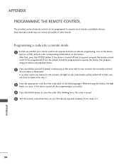
... not control all models of other brands. If not, the remote should be programmed. When pressing the button, the light blinks at the same time for 20 seconds, the light on the mode button will be programmed to repeat from step 2. 3 Enter the appropriate code from the code table on the remote. APPENDIX 94 If not, steps 2-5. APPENDIX PROGRAMMING THE REMOTE CONTROL The provided universal remote control can operate each device without programming, turn...
... not control all models of other brands. If not, the remote should be programmed. When pressing the button, the light blinks at the same time for 20 seconds, the light on the mode button will be programmed to repeat from step 2. 3 Enter the appropriate code from the code table on the remote. APPENDIX 94 If not, steps 2-5. APPENDIX PROGRAMMING THE REMOTE CONTROL The provided universal remote control can operate each device without programming, turn...

