

Owner's Manual
Page 4
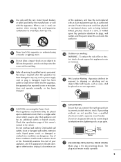
... safety instructions shall be placed immediately adjacent to be verbatim as radiators, heat registers, stoves, or other apparatus (including amplifiers)that produce heat. 6 Protect the power cord from being walked on or pinched particularly at plugs, convenience receptacles, and the point where they exit from the apparatus. 7 Only use and supplied...
... safety instructions shall be placed immediately adjacent to be verbatim as radiators, heat registers, stoves, or other apparatus (including amplifiers)that produce heat. 6 Protect the power cord from being walked on or pinched particularly at plugs, convenience receptacles, and the point where they exit from the apparatus. 7 Only use and supplied...
Owner's Manual
Page 5
..., and do not expose this apparatus or antenna during a thunder or lighting storm. 11 Do not allow a impact shock or any way, such as power-supply cord or plug is used, use marking : WARNING - To reduce the risk of fire or electric shock, do not drop onto the screen with... placed on or over . Do not try to ground the unit by the manufacturer, or sold with the apparatus. Protect the power cord from tip-over apparatus. 13 CAUTION concerning the Power Cord : Most appliances recommend they be certain. 9 Use only with the cart, stand, tripod, bracket, or table specified by...
..., and do not expose this apparatus or antenna during a thunder or lighting storm. 11 Do not allow a impact shock or any way, such as power-supply cord or plug is used, use marking : WARNING - To reduce the risk of fire or electric shock, do not drop onto the screen with... placed on or over . Do not try to ground the unit by the manufacturer, or sold with the apparatus. Protect the power cord from tip-over apparatus. 13 CAUTION concerning the Power Cord : Most appliances recommend they be certain. 9 Use only with the cart, stand, tripod, bracket, or table specified by...
Owner's Manual
Page 6
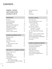
...Level 49 Image Sticking Minimization (ISM) Method 50 Low - Screen Setup for Wire Arrangement 10 Attaching the TV to a Wall 11 Use Power Cord Holder 11 Desktop Pedestal Installation 12 Protection Cover 12 Antenna or Cable Connection 13 EXTERNAL EQUIPMENT SETUP HD Receiver Setup 14 DVD Setup ...17 VCR Setup 19 Other A/V Source Setup 21 PC Setup 22 - Auto Scan (Auto Tuning 32 - Picture Mode - Power Picture Mode 51 Picture Reset 52 SOUND & LANGUAGE CONTROL Preset Sound Setting (Sound Mode 53 Sound Frequency Adjustment 54 Auto Volume Leveler 55 ...
...Level 49 Image Sticking Minimization (ISM) Method 50 Low - Screen Setup for Wire Arrangement 10 Attaching the TV to a Wall 11 Use Power Cord Holder 11 Desktop Pedestal Installation 12 Protection Cover 12 Antenna or Cable Connection 13 EXTERNAL EQUIPMENT SETUP HD Receiver Setup 14 DVD Setup ...17 VCR Setup 19 Other A/V Source Setup 21 PC Setup 22 - Auto Scan (Auto Tuning 32 - Picture Mode - Power Picture Mode 51 Picture Reset 52 SOUND & LANGUAGE CONTROL Preset Sound Setting (Sound Mode 53 Sound Frequency Adjustment 54 Auto Volume Leveler 55 ...
Owner's Manual
Page 9
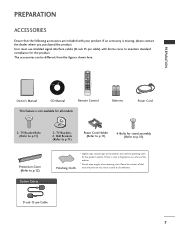
Please be different from the figures shown here. Owner's Manual Copyright© 2007 LGE, All Rights Reserved. CD Manual POWER TV 1 4 7 INPUT 2 3 5 6 8 9 0 MUTE RATIO EXIT MENU ENTER CH VOL VOL CH FAV REVIEW CH EDIT SLEEP CAPTION MTS SIZE POSITION PIP...on surface of that the following accessories are included with ferrite cores to maintain standard compliance for all models 1.5V 1.5V Batteries Power Cord 2- Wall Brackets (Refer to p.11) Power Cord Holder (Refer to p.11) 4-Bolts for stand assembly (Refer to p.10) Protection Cover (Refer to p.11) ...
Please be different from the figures shown here. Owner's Manual Copyright© 2007 LGE, All Rights Reserved. CD Manual POWER TV 1 4 7 INPUT 2 3 5 6 8 9 0 MUTE RATIO EXIT MENU ENTER CH VOL VOL CH FAV REVIEW CH EDIT SLEEP CAPTION MTS SIZE POSITION PIP...on surface of that the following accessories are included with ferrite cores to maintain standard compliance for all models 1.5V 1.5V Batteries Power Cord 2- Wall Brackets (Refer to p.11) Power Cord Holder (Refer to p.11) 4-Bolts for stand assembly (Refer to p.10) Protection Cover (Refer to p.11) ...

Owner's Manual
Page 10
PREPARATION Remote Control Sensor Power/Standby Indicator Illuminates red in standby mode. PREPARATION FRONT PANEL INFORMATION I NOTE: If your product has a protection tape attached, remove the tape. Illuminates green when the set is included with your TV. INPUT MENU ENTER VOL CH INPUT MENU ENTER VOL CH POWER Button INPUT Button MENU Button ENTER Button VOLUME (F,G)Buttons CHANNEL (E,D)Buttons 8 And then wipe the product with a cloth (If a polishing cloth is switched on. I Here shown may be somewhat different from your product, use it).
PREPARATION Remote Control Sensor Power/Standby Indicator Illuminates red in standby mode. PREPARATION FRONT PANEL INFORMATION I NOTE: If your product has a protection tape attached, remove the tape. Illuminates green when the set is included with your TV. INPUT MENU ENTER VOL CH INPUT MENU ENTER VOL CH POWER Button INPUT Button MENU Button ENTER Button VOLUME (F,G)Buttons CHANNEL (E,D)Buttons 8 And then wipe the product with a cloth (If a polishing cloth is switched on. I Here shown may be somewhat different from your product, use it).

Owner's Manual
Page 11
Or DVI(VIDEO)signal to HDMI/DVI port with DVI to HDMI cable. 7 ANTENNA IN Connect over-the-air signals to this jack. 8 Power Cord Socket This TV operates on DC power. 9 PREPARATION BACK PANEL INFORMATION 8 1 2 3 4 5 6 3 1 COMPONENT IN 1/2 Connect a component video/audio device to these jacks. 6 HDMI/DVI IN 1, HDMI IN 2... Connect a HDMI signal to HDMI IN. Never attempt to operate the TV on an AC power. AUDIO IN (RGB/DVI) Connect the audio from a PC or DTV. 4 AV OUT Connect second TV or monitor to your surround sound system. 3 ...
Or DVI(VIDEO)signal to HDMI/DVI port with DVI to HDMI cable. 7 ANTENNA IN Connect over-the-air signals to this jack. 8 Power Cord Socket This TV operates on DC power. 9 PREPARATION BACK PANEL INFORMATION 8 1 2 3 4 5 6 3 1 COMPONENT IN 1/2 Connect a component video/audio device to these jacks. 6 HDMI/DVI IN 1, HDMI IN 2... Connect a HDMI signal to HDMI IN. Never attempt to operate the TV on an AC power. AUDIO IN (RGB/DVI) Connect the audio from a PC or DTV. 4 AV OUT Connect second TV or monitor to your surround sound system. 3 ...

Owner's Manual
Page 13
... is mounted on the wall to the holes in a forward direction, potentially causing injury or damaging the product. It is not available for fixing the power cord. 11 Match the height of the TV by using the bracket for all models. Caution: Please make sure that children don't climb on the... back cover and fix the power cord at the rear side of the bracket that the TV be attached to a wall so it cannot be somewhat different from the TV. I Insert...
... is mounted on the wall to the holes in a forward direction, potentially causing injury or damaging the product. It is not available for fixing the power cord. 11 Match the height of the TV by using the bracket for all models. Caution: Please make sure that children don't climb on the... back cover and fix the power cord at the rear side of the bracket that the TV be attached to a wall so it cannot be somewhat different from the TV. I Insert...
Owner's Manual
Page 16
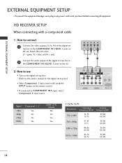
EXTERNAL EQUIPMENT SETUP EXTERNAL EQUIPMENT SETUP I If connected to COMPONENT IN2 input, select Component 2 input source. I To prevent the equipment damage, never plug in any power cords until you have finished connecting all equipment. HD RECEIVER SETUP When connecting with using the INPUT button on the remote control. Y PB PR L R 1 2 Signal ...
EXTERNAL EQUIPMENT SETUP EXTERNAL EQUIPMENT SETUP I If connected to COMPONENT IN2 input, select Component 2 input source. I To prevent the equipment damage, never plug in any power cords until you have finished connecting all equipment. HD RECEIVER SETUP When connecting with using the INPUT button on the remote control. Y PB PR L R 1 2 Signal ...
Owner's Manual
Page 25
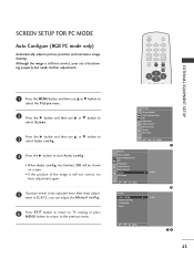
... not correct, your set is still not correct, try Auto adjustment again. 5 If picture needs to start Auto config.. • When Auto config. Manual Config. POWER TV 1 4 7 INPUT 2 3 5 6 8 9 0 MUTE RATIO EXIT MENU ENTER CH VOL VOL CH EXTERNAL EQUIPMENT SETUP 1 Press the MENU button and then use D or E button to select...
... not correct, your set is still not correct, try Auto adjustment again. 5 If picture needs to start Auto config.. • When Auto config. Manual Config. POWER TV 1 4 7 INPUT 2 3 5 6 8 9 0 MUTE RATIO EXIT MENU ENTER CH VOL VOL CH EXTERNAL EQUIPMENT SETUP 1 Press the MENU button and then use D or E button to select...
Owner's Manual
Page 26
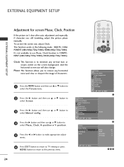
... XD Demo DE F G MENU 1 Picture Picture Mode Color Temperature XD Advanced Aspect Ratio Picture Reset Screen XD Demo G To Set DE F G MENU Screen Auto Config. POWER TV 1 4 7 INPUT 2 3 5 6 8 9 0 MUTE RATIO EXIT MENU ENTER CH VOL VOL CH Clock This function is to the previous menu. This function works in COMPONENT (480i...
... XD Demo DE F G MENU 1 Picture Picture Mode Color Temperature XD Advanced Aspect Ratio Picture Reset Screen XD Demo G To Set DE F G MENU Screen Auto Config. POWER TV 1 4 7 INPUT 2 3 5 6 8 9 0 MUTE RATIO EXIT MENU ENTER CH VOL VOL CH Clock This function is to the previous menu. This function works in COMPONENT (480i...

Owner's Manual
Page 27
... Ratio Picture Reset Screen XD Demo G To Set DE F G MENU 2 Screen Auto Config. VGA Mode Reset G 640x480 848x480 852x480 DE F G MENU 34 25 Manual Config. POWER TV 1 4 7 INPUT 2 3 5 6 8 9 0 MUTE RATIO EXIT MENU ENTER CH VOL VOL CH EXTERNAL EQUIPMENT SETUP 1 Press the MENU button and then use D or E button to select...
... Ratio Picture Reset Screen XD Demo G To Set DE F G MENU 2 Screen Auto Config. VGA Mode Reset G 640x480 848x480 852x480 DE F G MENU 34 25 Manual Config. POWER TV 1 4 7 INPUT 2 3 5 6 8 9 0 MUTE RATIO EXIT MENU ENTER CH VOL VOL CH EXTERNAL EQUIPMENT SETUP 1 Press the MENU button and then use D or E button to select...
Owner's Manual
Page 28
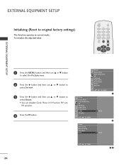
... Config. Manual Config. EXTERNAL EQUIPMENT SETUP Initializing (Reset to select Reset. • You can initialize Clock, Phase, H/V-Position, PIP size, PIP position. 4 Press the G button. POWER TV 1 4 7 INPUT 2 3 5 6 8 9 0 MUTE RATIO EXIT MENU ENTER CH VOL VOL CH EXTERNAL EQUIPMENT SETUP 1 Press the MENU button and then use D or E button to select...
... Config. Manual Config. EXTERNAL EQUIPMENT SETUP Initializing (Reset to select Reset. • You can initialize Clock, Phase, H/V-Position, PIP size, PIP position. 4 Press the G button. POWER TV 1 4 7 INPUT 2 3 5 6 8 9 0 MUTE RATIO EXIT MENU ENTER CH VOL VOL CH EXTERNAL EQUIPMENT SETUP 1 Press the MENU button and then use D or E button to select...
Owner's Manual
Page 30
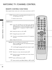
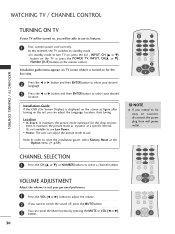
....G p.33 SLEEP Select the amount of AV devices connected to select the desired input source (TV, AV, Component 1, Component 2, RGB PC, HDMI1 or HDMI2). G p.58 POWER TV 1 4 7 INPUT 2 3 5 6 8 9 0 MUTE RATIO EXIT MENU ENTER CH VOL CH VOL FAV REVIEW CH EDIT SLEEP CAPTION MTS SIZE POSITION PIP PIP CH - Press the..., the input source OSD will appear on the TV. G p.60 MTS Selects the MTS sound: Mono, Stereo, or SAP. G p.30 RATIO Change the aspect ratio. POWER Turns your TV turns off , depending on the mode. MENU Displays the main menu.
....G p.33 SLEEP Select the amount of AV devices connected to select the desired input source (TV, AV, Component 1, Component 2, RGB PC, HDMI1 or HDMI2). G p.58 POWER TV 1 4 7 INPUT 2 3 5 6 8 9 0 MUTE RATIO EXIT MENU ENTER CH VOL CH VOL FAV REVIEW CH EDIT SLEEP CAPTION MTS SIZE POSITION PIP PIP CH - Press the..., the input source OSD will appear on the TV. G p.60 MTS Selects the MTS sound: Mono, Stereo, or SAP. G p.30 RATIO Change the aspect ratio. POWER Turns your TV turns off , depending on the mode. MENU Displays the main menu.

Owner's Manual
Page 31
... * Not functional Installing Batteries Remote control effective range I Open the battery compartment cover on -screen menus and adjust the system settings to preserve environment. 29 R POWER TV 1 4 7 INPUT 2 3 5 6 8 9 0 MUTE I Close cover. G p.40 PIP INPUT Selects the input source for the sub picture. Don't mix old or used batteries in PIP/DW...
... * Not functional Installing Batteries Remote control effective range I Open the battery compartment cover on -screen menus and adjust the system settings to preserve environment. 29 R POWER TV 1 4 7 INPUT 2 3 5 6 8 9 0 MUTE I Close cover. G p.40 PIP INPUT Selects the input source for the sub picture. Don't mix old or used batteries in PIP/DW...
Owner's Manual
Page 32
... select your desired location. It maintains the picture mode as figure after turning on the set, you will be turned on vacation, disconnect the power plug from wall power outlet. 1 4 7 INPUT 2 3 5 6 8 9 0 MUTE RATIO EXIT MENU ENTER CH VOL VOL CH 7 INPUT 8 9 0 MUTE RATIO EXIT MENU ENTER ...control. WATCHING TV / CHANNEL CONTROL WATCHING TV / CHANNEL CONTROL TURNING ON TV If your TV will be able to use its features. 1 First, connect power cord correctly. At this moment, the TV switches to select a channel number. I In standby mode to turn TV on, press the , INPUT, ...
... select your desired location. It maintains the picture mode as figure after turning on the set, you will be turned on vacation, disconnect the power plug from wall power outlet. 1 4 7 INPUT 2 3 5 6 8 9 0 MUTE RATIO EXIT MENU ENTER CH VOL VOL CH 7 INPUT 8 9 0 MUTE RATIO EXIT MENU ENTER ...control. WATCHING TV / CHANNEL CONTROL WATCHING TV / CHANNEL CONTROL TURNING ON TV If your TV will be able to use its features. 1 First, connect power cord correctly. At this moment, the TV switches to select a channel number. I In standby mode to turn TV on, press the , INPUT, ...

Owner's Manual
Page 33
... Demo DE F G MENU Picture Audio Sound Mode Auto Volume Balance 0 TV Speaker DE F G MENU Audio Option Language SIMPLINK Key Lock Caption/Text ISM Method Low Power Lock Factory Reset DE F G MENU Option Time Clock Off Time On Time Sleep Time Auto Sleep DE F G MENU Time 31
... Demo DE F G MENU Picture Audio Sound Mode Auto Volume Balance 0 TV Speaker DE F G MENU Audio Option Language SIMPLINK Key Lock Caption/Text ISM Method Low Power Lock Factory Reset DE F G MENU Option Time Clock Off Time On Time Sleep Time Auto Sleep DE F G MENU Time 31
Owner's Manual
Page 34
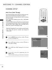
... Tuning) Auto Tuning should be used to memorize all the active channels in your area before you are able to at that time are memorized. POWER TV 1 4 7 INPUT 2 3 5 6 8 9 0 MUTE RATIO EXIT MENU ENTER CH VOL VOL CH Setup Auto Tuning Manual Tuning Favorite Channel 1 Press the M E N U button and then use D or...
... Tuning) Auto Tuning should be used to memorize all the active channels in your area before you are able to at that time are memorized. POWER TV 1 4 7 INPUT 2 3 5 6 8 9 0 MUTE RATIO EXIT MENU ENTER CH VOL VOL CH Setup Auto Tuning Manual Tuning Favorite Channel 1 Press the M E N U button and then use D or...

Owner's Manual
Page 36
POWER TV 1 4 7 INPUT 2 3 5 6 8 9 0 MUTE RATIO EXIT MENU ENTER CH VOL VOL CH WATCHING TV / CHANNEL CONTROL 1 Press the M E N U button and then use D or E button to select ...
POWER TV 1 4 7 INPUT 2 3 5 6 8 9 0 MUTE RATIO EXIT MENU ENTER CH VOL VOL CH WATCHING TV / CHANNEL CONTROL 1 Press the M E N U button and then use D or E button to select ...

Owner's Manual
Page 38
... remote control, you can stop the operation of the simplink device with the audio cable. Option Language SIMPLINK Key lock Caption/Text ISM Method Low Power Lock Factory Reset DE F G MENU 1 4 Press EXIT button to return to TV viewing or press MENU button to return to select O n or O...) of the Simplink device with the I N P U T button on the back of device worked by Simplink. G When you switch the Input source with the HDMI cable. POWER TV 1 4 7 INPUT 2 3 5 6 8 9 0 MUTE RATIO EXIT MENU ENTER CH VOL VOL CH 1 Press the M E N U button and then use D or E button to select ...
... remote control, you can stop the operation of the simplink device with the audio cable. Option Language SIMPLINK Key lock Caption/Text ISM Method Low Power Lock Factory Reset DE F G MENU 1 4 Press EXIT button to return to TV viewing or press MENU button to return to select O n or O...) of the Simplink device with the I N P U T button on the back of device worked by Simplink. G When you switch the Input source with the HDMI cable. POWER TV 1 4 7 INPUT 2 3 5 6 8 9 0 MUTE RATIO EXIT MENU ENTER CH VOL VOL CH 1 Press the M E N U button and then use D or E button to select ...

Owner's Manual
Page 39
... is on the PLAY mode, F G buttons are available to adjust the volume, but does not support SimpLink, does not provide this function. I Power off all devices: When you power off TV, all connected devices are conveniently displayed at the 2 bottom of the current mode. 2 DISC playback: Select and play media without additional...
... is on the PLAY mode, F G buttons are available to adjust the volume, but does not support SimpLink, does not provide this function. I Power off all devices: When you power off TV, all connected devices are conveniently displayed at the 2 bottom of the current mode. 2 DISC playback: Select and play media without additional...

