
Service Manual
Page 1
website:http://biz.LGservice.com e-mail:http://www.LGEservice.com/techsup.html LCD TV SERVICE MANUAL CHASSIS : ML-051A MODEL : 32LX2R-TE CAUTION BEFORE SERVICING THE CHASSIS, READ THE SAFETY PRECAUTIONS IN THIS MANUAL.
website:http://biz.LGservice.com e-mail:http://www.LGEservice.com/techsup.html LCD TV SERVICE MANUAL CHASSIS : ML-051A MODEL : 32LX2R-TE CAUTION BEFORE SERVICING THE CHASSIS, READ THE SAFETY PRECAUTIONS IN THIS MANUAL.
Service Manual
Page 2
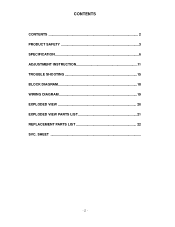
CONTENTS CONTENTS 2 PRODUCT SAFETY 3 SPECIFICATION 6 ADJUSTMENT INSTRUCTION 11 TROUBLE SHOOTING 15 BLOCK DIAGRAM 18 WIRING DIAGRAM 19 EXPLODED VIEW 20 EXPLODED VIEW PARTS LIST 21 REPLACEMENT PARTS LIST 22 SVC. SHEET -2-
CONTENTS CONTENTS 2 PRODUCT SAFETY 3 SPECIFICATION 6 ADJUSTMENT INSTRUCTION 11 TROUBLE SHOOTING 15 BLOCK DIAGRAM 18 WIRING DIAGRAM 19 EXPLODED VIEW 20 EXPLODED VIEW PARTS LIST 21 REPLACEMENT PARTS LIST 22 SVC. SHEET -2-
Service Manual
Page 3
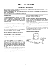
... ohm-meter lead in turn to the AC plug prongs tied together and touch other Hazards. Do not use a line Isolation Transformer during the service operation. Any voltage measured must be infinite. Leakage Current Cold Check(Antenna Cold Check) With the instrument AC plug removed from being damaged by in the Schematic Diagram and Replacement Parts List. Place the AC switch in the on...
... ohm-meter lead in turn to the AC plug prongs tied together and touch other Hazards. Do not use a line Isolation Transformer during the service operation. Any voltage measured must be infinite. Leakage Current Cold Check(Antenna Cold Check) With the instrument AC plug removed from being damaged by in the Schematic Diagram and Replacement Parts List. Place the AC switch in the on...
Service Manual
Page 4
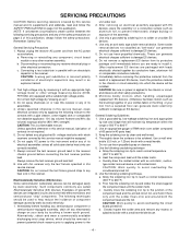
... foil. Use a grounded-tip, low-wattage soldering iron and appropriate tip size and shape that will be equipped. 6. Heat the component lead until the solder melts. Quickly draw the melted solder with solder braid. CAUTION: Work quickly to 600 F. 2. Closely inspect the solder area and remove any receiver electrical plug or other safety precautions. 8. SERVICING PRECAUTIONS CAUTION: Before servicing receivers covered...
... foil. Use a grounded-tip, low-wattage soldering iron and appropriate tip size and shape that will be equipped. 6. Heat the component lead until the solder melts. Quickly draw the melted solder with solder braid. CAUTION: Work quickly to 600 F. 2. Closely inspect the solder area and remove any receiver electrical plug or other safety precautions. 8. SERVICING PRECAUTIONS CAUTION: Before servicing receivers covered...

Service Manual
Page 5
... involves the installation of a jumper wire on the other than IC Pins. Replacement 1. Insert new transistor in the circuit board. 2. At IC Connections To repair a defective copper pattern at least 1/4 inch of the pattern break and locate the nearest component that bonds ... 3. Circuit Board Foil Repair Excessive heat applied to the copper foil of the nearest component on the component side of the circuit board. (Use this condition is directly connected to diode body. 2. Bend a small "U" in one operation by clipping its leads as close as possible to the ...
... involves the installation of a jumper wire on the other than IC Pins. Replacement 1. Insert new transistor in the circuit board. 2. At IC Connections To repair a defective copper pattern at least 1/4 inch of the pattern break and locate the nearest component that bonds ... 3. Circuit Board Foil Repair Excessive heat applied to the copper foil of the nearest component on the component side of the circuit board. (Use this condition is directly connected to diode body. 2. Bend a small "U" in one operation by clipping its leads as close as possible to the ...
Service Manual
Page 6
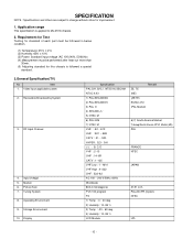
... below condition. (1) Temperature: 25°C ± 2°C (2) Humidity: 65% ± 10% (3) Power: Standard input voltage (AC 100-240V, 50/60Hz) (4) Measurement must be performed after heat-run more than 30min. (5) Adjusting standard for improvement. 1. Operating Environment 9. RF Input Channel 4. Storage Environment 10. Receivable Broadcasting System 3. Display Specification PAL-D/K, B/G, I, NTSC-M, SECAM NTSC 4.43 1) PAL/SECAM BG 2) PAL/SECAM DK...
... below condition. (1) Temperature: 25°C ± 2°C (2) Humidity: 65% ± 10% (3) Power: Standard input voltage (AC 100-240V, 50/60Hz) (4) Measurement must be performed after heat-run more than 30min. (5) Adjusting standard for improvement. 1. Operating Environment 9. RF Input Channel 4. Storage Environment 10. Receivable Broadcasting System 3. Display Specification PAL-D/K, B/G, I, NTSC-M, SECAM NTSC 4.43 1) PAL/SECAM BG 2) PAL/SECAM DK...
Service Manual
Page 7
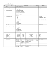
... 3 Control Function 4 Component Jack D4 Jack (525i,525p,750p,1125i) 5 Power ON Stand by DPMS Mode Power off 6 LCD Module Specification 32" TFT WXGA LCD H : 31 ~ 61Khz V : 56 ~ 75Hz 1) Contrast/Brightness 2) H-Position / V-Position 3) Tracking : Clock / Phase 4) Auto Configure 5) Reset 1 : Y 3 : Pb 5 : Pr 7 : Line1 Ready 9 : LINE2 11: LINE3 13: Line3 Ready 2 : Y GND 4 : Pb GND 6 : Pr GND 8 : LINE1 10:Line2 Ready 12:SWITCH GND 14: SWITCH H/V-Sync Video Power consumption ON...
... 3 Control Function 4 Component Jack D4 Jack (525i,525p,750p,1125i) 5 Power ON Stand by DPMS Mode Power off 6 LCD Module Specification 32" TFT WXGA LCD H : 31 ~ 61Khz V : 56 ~ 75Hz 1) Contrast/Brightness 2) H-Position / V-Position 3) Tracking : Clock / Phase 4) Auto Configure 5) Reset 1 : Y 3 : Pb 5 : Pr 7 : Line1 Ready 9 : LINE2 11: LINE3 13: Line3 Ready 2 : Y GND 4 : Pb GND 6 : Pr GND 8 : LINE1 10:Line2 Ready 12:SWITCH GND 14: SWITCH H/V-Sync Video Power consumption ON...
Service Manual
Page 9
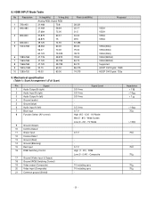
...0.4V) - TV Mode - 0.7 V 0.7 V High (1 - 3V) - 8. Mechanical specification Scart Arrangement 1.(Full Scart) Pin Signal 1 Audio Output B (right) 2 Audio Input B (right) 3 Audio Output A (left) 4 Ground (audio) 5 Ground (blue) 6 Audio input A (left) 7 Blue input 8 Function Select (AV control) 9 Ground (Green) 10 Comms Data 2 11 Green input 12 Comms Data 1 13 Ground (Red) 14 Ground (Blanking) 15 Red input 16 RGB Switching Control 17 Ground (Video input & Output) 18 Ground (RGB Switching Control) 19 Video output (Composite) 20 Video input (Composite) 21...
...0.4V) - TV Mode - 0.7 V 0.7 V High (1 - 3V) - 8. Mechanical specification Scart Arrangement 1.(Full Scart) Pin Signal 1 Audio Output B (right) 2 Audio Input B (right) 3 Audio Output A (left) 4 Ground (audio) 5 Ground (blue) 6 Audio input A (left) 7 Blue input 8 Function Select (AV control) 9 Ground (Green) 10 Comms Data 2 11 Green input 12 Comms Data 1 13 Ground (Red) 14 Ground (Blanking) 15 Red input 16 RGB Switching Control 17 Ground (Video input & Output) 18 Ground (RGB Switching Control) 19 Video output (Composite) 20 Video input (Composite) 21...
Service Manual
Page 10
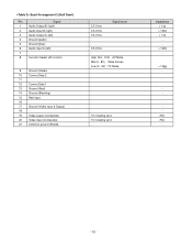
... Screen Low (0 - 2V) - TV Mode - - - 1V including sync 1V including sync - Scart Arrangement 2.(Half Scart) Pin Signal 1 Audio Output B (right) 2 Audio Input B (right) 3 Audio Output A (left) 4 Ground (audio) 5 Ground (blue) 6 Audio input A (left) 7 - 8 Function Select (AV control) 9 Ground (Green) 10 Comms Data 2 11 - 12 Comms Data 1 13 Ground (Red) 14 Ground (Blanking) 15 Red input 16 - 17 Ground (Video input & Output) 18 - 19 Video output (Composite) 20 Video input (Composite) 21 Common ground (Shield) Signal...
... Screen Low (0 - 2V) - TV Mode - - - 1V including sync 1V including sync - Scart Arrangement 2.(Half Scart) Pin Signal 1 Audio Output B (right) 2 Audio Input B (right) 3 Audio Output A (left) 4 Ground (audio) 5 Ground (blue) 6 Audio input A (left) 7 - 8 Function Select (AV control) 9 Ground (Green) 10 Comms Data 2 11 - 12 Comms Data 1 13 Ground (Red) 14 Ground (Blanking) 15 Red input 16 - 17 Ground (Video input & Output) 18 - 19 Video output (Composite) 20 Video input (Composite) 21 Common ground (Shield) Signal...
Service Manual
Page 11
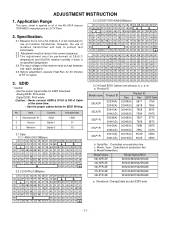
.... Never connect HDMI & DVI-D & DVI-A Cable at RF no signal. 3. Application Range This spec. Serial No : Controlled on production line d. Model Name(Hex) : Model Name Model Name(HEX) 26LX2R-ZE 32364C5832522D5A45 32LX2R-ZE 33324C5832522D5A45 32LP1R-ZE 33324C5031522D5A45 37LP1R-ZE 33374C5031522D5A45 42LP1R-ZE 34324C5031522D5A45 e. EDID * Caution - Month, Year : Controlled on production line c. sheet is no specified designation. 2.4 The input voltage of isolation transformer will help to protect...
.... Never connect HDMI & DVI-D & DVI-A Cable at RF no signal. 3. Application Range This spec. Serial No : Controlled on production line d. Model Name(Hex) : Model Name Model Name(HEX) 26LX2R-ZE 32364C5832522D5A45 32LX2R-ZE 33324C5832522D5A45 32LP1R-ZE 33324C5031522D5A45 37LP1R-ZE 33374C5031522D5A45 42LP1R-ZE 34324C5031522D5A45 e. EDID * Caution - Month, Year : Controlled on production line c. sheet is no specified designation. 2.4 The input voltage of isolation transformer will help to protect...
Service Manual
Page 12
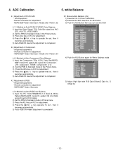
... Auto RGB Color Balance 1) Input the PC 1024x768@60Hz 1/2 Black & White Pattern(MSPG-925F model:37, pattern:18) into Component. (ZE : component , TE/ME : component 1 or 2) 2) Set the PSM to Standard mode in the Picture menu. 3) Press the ADJ key on R/C for adjustment. 4) Press the (Vol. +) key to Standard mode in Picture menu. 3) Press the ADJ key on R/C for adjustment - ADC Calibration 5. Remote controller for adjustment - Remote controller for adjustment. 4) Press the (Vol. +) key operate...
... Auto RGB Color Balance 1) Input the PC 1024x768@60Hz 1/2 Black & White Pattern(MSPG-925F model:37, pattern:18) into Component. (ZE : component , TE/ME : component 1 or 2) 2) Set the PSM to Standard mode in the Picture menu. 3) Press the ADJ key on R/C for adjustment. 4) Press the (Vol. +) key to Standard mode in Picture menu. 3) Press the ADJ key on R/C for adjustment - ADC Calibration 5. Remote controller for adjustment - Remote controller for adjustment. 4) Press the (Vol. +) key operate...
Service Manual
Page 13
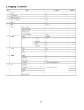
Shipping Conditions No 1 Power 2 Volume Level 3 Main Picture Input 4 Main Last Channel 5 Mute 6 ARC 7 Station 8 Picture Item Auto Program Manual Program Program Edit Favorite Program PSM Dynamic 9 Sound 10 Special 11 PC SSM AVL Balance Input Child Lock Auto sleep Language H-Position V-Position Clock Phase Auto Configue Contrast Brightness Colour Sharpness Off 30 TV Pr 01 Off 16 : 9 Condition None Dynamic 100 45 50 50 Flat Off 0 TV Off Off English(Area Management) Variable by each mode Remark - 13 - 6.
Shipping Conditions No 1 Power 2 Volume Level 3 Main Picture Input 4 Main Last Channel 5 Mute 6 ARC 7 Station 8 Picture Item Auto Program Manual Program Program Edit Favorite Program PSM Dynamic 9 Sound 10 Special 11 PC SSM AVL Balance Input Child Lock Auto sleep Language H-Position V-Position Clock Phase Auto Configue Contrast Brightness Colour Sharpness Off 30 TV Pr 01 Off 16 : 9 Condition None Dynamic 100 45 50 50 Flat Off 0 TV Off Off English(Area Management) Variable by each mode Remark - 13 - 6.
Service Manual
Page 14
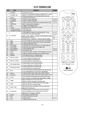
.... Use the AV To adjust the screen voltage (automatic): key to closed caption broadcasting 8 TXT To toggle on/off 2 POWER ON To turn the TV on or off the teletext mode 9 TV/AV To select an external input for the TV screen 10 TURBO SOUND To start turbo sound 11 TURBO PICTURE To start mute Adjust AV(Enter into W/B adjustment mode) the screen W/B W/B adjustment (automatic): adjustment After adjusting the screen W/B adjustment Exit two times (Adjustment completed) mode...
.... Use the AV To adjust the screen voltage (automatic): key to closed caption broadcasting 8 TXT To toggle on/off 2 POWER ON To turn the TV on or off the teletext mode 9 TV/AV To select an external input for the TV screen 10 TURBO SOUND To start turbo sound 11 TURBO PICTURE To start mute Adjust AV(Enter into W/B adjustment mode) the screen W/B W/B adjustment (automatic): adjustment After adjusting the screen W/B adjustment Exit two times (Adjustment completed) mode...
Service Manual
Page 17
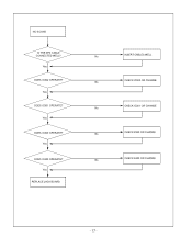
Yes DOES IC302 OPERATE? Yes DOES IC301 OPERATE? NO SOUND IS THE SPK CABLE CONNECTED WELL? Yes DOES IC300 OPERATE? Yes REPLACE JACK BOARD INSERT CABLES WELL No CHECK IC302 OR CHANGE No CHECK IC301 OR CHANGE No CHECK X300 OR CHANGE No CHECK X400 OR CHANGE No - 17 - Yes DOES IC400 OPERATE?
Yes DOES IC302 OPERATE? Yes DOES IC301 OPERATE? NO SOUND IS THE SPK CABLE CONNECTED WELL? Yes DOES IC300 OPERATE? Yes REPLACE JACK BOARD INSERT CABLES WELL No CHECK IC302 OR CHANGE No CHECK IC301 OR CHANGE No CHECK X300 OR CHANGE No CHECK X400 OR CHANGE No - 17 - Yes DOES IC400 OPERATE?
Service Manual
Page 21
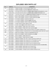
... - DESCRIPTION 010 3091TKE037C CABINET ASSEMBLY, 32LX2R-ZE BRAND CABINET ASSY 3091TKE037D CABINET ASSEMBLY, 32LX2R-ZE CSKD BRAND CABINET ASSY 020 6304FLP290A LCD(LIQUID CRYSTAL DISPLAY), LC320W01-A6K6 LG PHILPS TFT COLOR WXGA AIODC or 6304FLP181A LCD(LIQUID CRYSTAL DISPLAY), LC320W01-A6K3 LG PHILPS TFT COLOR AI ODC 6304FLP332A LCD(LIQUID CRYSTAL DISPLAY), LC320W01-SL05 LG PHILPS TFT COLOR (SL01, D-IC,INV. EXPLODED VIEW PARTS LIST No. PART NO.
... - DESCRIPTION 010 3091TKE037C CABINET ASSEMBLY, 32LX2R-ZE BRAND CABINET ASSY 3091TKE037D CABINET ASSEMBLY, 32LX2R-ZE CSKD BRAND CABINET ASSY 020 6304FLP290A LCD(LIQUID CRYSTAL DISPLAY), LC320W01-A6K6 LG PHILPS TFT COLOR WXGA AIODC or 6304FLP181A LCD(LIQUID CRYSTAL DISPLAY), LC320W01-A6K3 LG PHILPS TFT COLOR AI ODC 6304FLP332A LCD(LIQUID CRYSTAL DISPLAY), LC320W01-SL05 LG PHILPS TFT COLOR (SL01, D-IC,INV. EXPLODED VIEW PARTS LIST No. PART NO.

Service Manual
Page 22
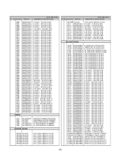
...10% X7R 2012 R/TP - 22 - PART NO. CC, CX, CK, CN, CH : Ceramic CQ : Polyestor CE : Electrolytic CF : Fixed Film RD : Carbon Film RS : Metal Oxide Film RN : Metal Film RH : CHIP, Metal Glazed(Chip) RR : Drawing *S *AL LOC. CAPACITOR DATE: 2005. 09. 06. DESCRIPTION / SPECIFICATION C1008 C1010 C1011 C1014 C1015 C1016...10% X7R 2012 R/TP 0.1UF 50V 10% X7R 2012 R/TP 0.1UF 50V 10% X7R 2012 R/TP 10000PF 50V 10% B(Y5P) 2012 *S *AL LOC. NO. REPLACEMENT PARTS LIST For Capacitor & Resistors, the charactors at 2nd and 3rd digit in the P/No. DATE: 2005. 09. 06. NO. means as follows;
...10% X7R 2012 R/TP - 22 - PART NO. CC, CX, CK, CN, CH : Ceramic CQ : Polyestor CE : Electrolytic CF : Fixed Film RD : Carbon Film RS : Metal Oxide Film RN : Metal Film RH : CHIP, Metal Glazed(Chip) RR : Drawing *S *AL LOC. CAPACITOR DATE: 2005. 09. 06. DESCRIPTION / SPECIFICATION C1008 C1010 C1011 C1014 C1015 C1016...10% X7R 2012 R/TP 0.1UF 50V 10% X7R 2012 R/TP 0.1UF 50V 10% X7R 2012 R/TP 10000PF 50V 10% B(Y5P) 2012 *S *AL LOC. NO. REPLACEMENT PARTS LIST For Capacitor & Resistors, the charactors at 2nd and 3rd digit in the P/No. DATE: 2005. 09. 06. NO. means as follows;
Service Manual
Page 28
...X800 0DL233309AC 166-E02F 156-A02X 6212AB2015G 6212AB2015G SAM2333 TP KWANG GREEN/RED CSBLA500KECZF09-B0 CSB500F9 HC49U SUNNY RADIAL 27.000MH HC-49/SM BUBANG 19.6608MHZ HC-49/SM BUBANG 19.6608MHZ CONTROL BOARD SW1201 140-313B SW1202 140-313B SW1203 140-313B SW1204 140... SW1207 140-313B TACT 2LEAD 160G(TA) LG C&D TACT 2LEAD 160G(TA) LG C&D TACT 2LEAD 160G(TA) LG C&D TACT 2LEAD 160G(TA) LG C&D TACT 2LEAD 160G(TA) LG C&D TACT 2LEAD 160G(TA) LG C&D TACT 2LEAD 160G(TA) LG C&D *S *AL LOC. PART NO. NO. DESCRIPTION / SPECIFICATION SW1208 140-313B R2111 0RH3001D622 R2112 0RH3001D622 R2113...
...X800 0DL233309AC 166-E02F 156-A02X 6212AB2015G 6212AB2015G SAM2333 TP KWANG GREEN/RED CSBLA500KECZF09-B0 CSB500F9 HC49U SUNNY RADIAL 27.000MH HC-49/SM BUBANG 19.6608MHZ HC-49/SM BUBANG 19.6608MHZ CONTROL BOARD SW1201 140-313B SW1202 140-313B SW1203 140-313B SW1204 140... SW1207 140-313B TACT 2LEAD 160G(TA) LG C&D TACT 2LEAD 160G(TA) LG C&D TACT 2LEAD 160G(TA) LG C&D TACT 2LEAD 160G(TA) LG C&D TACT 2LEAD 160G(TA) LG C&D TACT 2LEAD 160G(TA) LG C&D TACT 2LEAD 160G(TA) LG C&D *S *AL LOC. PART NO. NO. DESCRIPTION / SPECIFICATION SW1208 140-313B R2111 0RH3001D622 R2112 0RH3001D622 R2113...
Service Manual
Page 29
PART NO. DATE: 2005. 09. 06. *S *AL LOC. DESCRIPTION / SPECIFICATION LED804 0DLBE0158AA LED805 0DLBE0158AA LED806 0DLBE0158AA LED807 0DLBE0158AA BRIGHT LED ELECTRONICS BL-H BRIGHT LED ELECTRONICS BL-H BRIGHT LED ELECTRONICS BL-H BRIGHT LED ELECTRONICS BL-H SIDE BOARD C3103 0CH6102K406 C3104 0CH6102K406 L3108 6210TCE001A L3109 ...1K OHM 1 / 10 W 2012 5.00% UDZ S 5.1B TP ROHM-K SOD323 UDZ S 5.1B TP ROHM-K SOD323 UDZ S 5.1B TP ROHM-K SOD323 JACK BOARD C100 C1001 C103 C104 C105 C1102 C1146 C1147 C115 C116 C1169 C117 C1171 C1172 C118 C119 C120 C122 C123 C126 C128 C129 C1297 C1306...
PART NO. DATE: 2005. 09. 06. *S *AL LOC. DESCRIPTION / SPECIFICATION LED804 0DLBE0158AA LED805 0DLBE0158AA LED806 0DLBE0158AA LED807 0DLBE0158AA BRIGHT LED ELECTRONICS BL-H BRIGHT LED ELECTRONICS BL-H BRIGHT LED ELECTRONICS BL-H BRIGHT LED ELECTRONICS BL-H SIDE BOARD C3103 0CH6102K406 C3104 0CH6102K406 L3108 6210TCE001A L3109 ...1K OHM 1 / 10 W 2012 5.00% UDZ S 5.1B TP ROHM-K SOD323 UDZ S 5.1B TP ROHM-K SOD323 UDZ S 5.1B TP ROHM-K SOD323 JACK BOARD C100 C1001 C103 C104 C105 C1102 C1146 C1147 C115 C116 C1169 C117 C1171 C1172 C118 C119 C120 C122 C123 C126 C128 C129 C1297 C1306...

Service Manual
Page 31
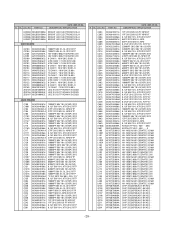
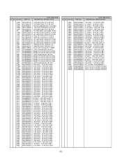
PART NO. NO. DESCRIPTION / SPECIFICATION R415 0RH4700D622 470 OHM 1 / 10 W 2012 5.00% R416 0RH4700D622 470 OHM 1 / 10 W 2012 5.00% R417 0RH4700D622 470 OHM 1 / 10 W 2012 5.00% R420 0RH4700D622 470 OHM 1 / ... KDS226 TP KEC - 80V - - 4NS 0DS226009AA KDS226 TP KEC - 80V - - 4NS 0DD184009AA KDS184 TP KEC - 85V - - - 3 0IMCRFA010A "KA7809R, FAIRCHILD 2P D-PAK" 0IMCRSH001A "PQ05DZ1U SHARP 5, SMD TYPE" 0IMCRSG010A ST3232CDR SGS-THOMSON SOP16 0IMCRMN028B MSP4410K MICRONAS 80P/PQFP 0IPRPTI034B "TPA6110A2DGNRG4,LF TEXAS IN" 0ISO206900A CXA2069Q QFP64 BK I2C BUS A 0DRSE00018B "SRV05-4.TCT, SEMTECH...
PART NO. NO. DESCRIPTION / SPECIFICATION R415 0RH4700D622 470 OHM 1 / 10 W 2012 5.00% R416 0RH4700D622 470 OHM 1 / 10 W 2012 5.00% R417 0RH4700D622 470 OHM 1 / 10 W 2012 5.00% R420 0RH4700D622 470 OHM 1 / ... KDS226 TP KEC - 80V - - 4NS 0DS226009AA KDS226 TP KEC - 80V - - 4NS 0DD184009AA KDS184 TP KEC - 85V - - - 3 0IMCRFA010A "KA7809R, FAIRCHILD 2P D-PAK" 0IMCRSH001A "PQ05DZ1U SHARP 5, SMD TYPE" 0IMCRSG010A ST3232CDR SGS-THOMSON SOP16 0IMCRMN028B MSP4410K MICRONAS 80P/PQFP 0IPRPTI034B "TPA6110A2DGNRG4,LF TEXAS IN" 0ISO206900A CXA2069Q QFP64 BK I2C BUS A 0DRSE00018B "SRV05-4.TCT, SEMTECH...
Service Manual
Page 32
PART NO. DATE: 2005. 09. 06. DESCRIPTION / SPECIFICATION IC605 IC606 IC607 IC608 IC609 JK1 L1002 L103 L218 L219 L300 L301... 3216M HH-1M3216-501 CERATEC 3216M 10022HS-31A02 YEONHO 31P 1. 10022HS-31A02 YEONHO 31P 1. NO. DESCRIPTION / SPECIFICATION R656 R657 R658 R659 R660 R663 R666 R669 R672 R673 R674 R675 R679 R680 R681 R682 R683 R684 R685 R690...+/UDZ S 5.1B TP ROHM-K SOD323 UDZ S 5.1B TP ROHM-K SOD323 UDZ S 5.1B TP ROHM-K SOD323 - 32 - NO. PART NO. GT121-31P-TD LGC 31P 1.25MM CHIP 2SA1504S(ASY) BK KEC BSS83 TP PHILIPS NON N-CHAN BSS83 TP PHILIPS NON N-CHAN CHIP 2SC3875S...
PART NO. DATE: 2005. 09. 06. DESCRIPTION / SPECIFICATION IC605 IC606 IC607 IC608 IC609 JK1 L1002 L103 L218 L219 L300 L301... 3216M HH-1M3216-501 CERATEC 3216M 10022HS-31A02 YEONHO 31P 1. 10022HS-31A02 YEONHO 31P 1. NO. DESCRIPTION / SPECIFICATION R656 R657 R658 R659 R660 R663 R666 R669 R672 R673 R674 R675 R679 R680 R681 R682 R683 R684 R685 R690...+/UDZ S 5.1B TP ROHM-K SOD323 UDZ S 5.1B TP ROHM-K SOD323 UDZ S 5.1B TP ROHM-K SOD323 - 32 - NO. PART NO. GT121-31P-TD LGC 31P 1.25MM CHIP 2SA1504S(ASY) BK KEC BSS83 TP PHILIPS NON N-CHAN BSS83 TP PHILIPS NON N-CHAN CHIP 2SC3875S...


