Specification (English)
Page 1
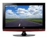
...enhances and amplifies the sound of the DTV system used in the US. Speakers are embedded in progressive scan DVD player. 32LG40 LCD HDTV WITH BUILT-IN DVD PLAYER 32" Class (31.5" diagonal) • 720p HD Resolution • 12,000:1 Dynamic Contrast Ratio • Side-loading ...behind the front cabinet and use minute vibrations to near 720p resolution and features LG "Super-Multi" technology which plays back almost any recordable disc based media. INVISIBLE SPEAKER SYSTEM LG's 2008 line of TVs include a unique invisible speaker system, tuned by increasing the "sweet spot" giving...
...enhances and amplifies the sound of the DTV system used in the US. Speakers are embedded in progressive scan DVD player. 32LG40 LCD HDTV WITH BUILT-IN DVD PLAYER 32" Class (31.5" diagonal) • 720p HD Resolution • 12,000:1 Dynamic Contrast Ratio • Side-loading ...behind the front cabinet and use minute vibrations to near 720p resolution and features LG "Super-Multi" technology which plays back almost any recordable disc based media. INVISIBLE SPEAKER SYSTEM LG's 2008 line of TVs include a unique invisible speaker system, tuned by increasing the "sweet spot" giving...

Owner's Manual (English)
Page 1
LCD TV / DVD Combo OWNER'S MANUAL 26LG40 32LG40 Please read this manual. CLASS 1M VISIBLE AND INVISIBLE LASER RADIATION WHEN OPEN DO NOT VIEW DIRECTLY WITH OPTICAL INSTRUMENTS P/NO : SAC31712401 (0810-REV06) www.lgusa.com / www.lg.ca Write the model number and serial number from the label on the back cabinet on the front or back of this manual carefully before operating your set and retain it for future reference. CAUTION -
LCD TV / DVD Combo OWNER'S MANUAL 26LG40 32LG40 Please read this manual. CLASS 1M VISIBLE AND INVISIBLE LASER RADIATION WHEN OPEN DO NOT VIEW DIRECTLY WITH OPTICAL INSTRUMENTS P/NO : SAC31712401 (0810-REV06) www.lgusa.com / www.lg.ca Write the model number and serial number from the label on the back cabinet on the front or back of this manual carefully before operating your set and retain it for future reference. CAUTION -
Owner's Manual (English)
Page 2
... party responsible for help. This equipment generates, uses and can be determined by turning the equipment off and on a circuit different from LG Electronics. Reorient or relocate the receiving antenna. - Connect the equipment to an outlet on , the user is encouraged to try to... cable ground shall be of sufficient magnitude to Part 15 of the National Electric Code (U.S.A.). Consult the dealer or an experienced radio/TV technician for compliance could void the user's authority to operate this product to the point of important operating and maintenance (servicing) instructions...
... party responsible for help. This equipment generates, uses and can be determined by turning the equipment off and on a circuit different from LG Electronics. Reorient or relocate the receiving antenna. - Connect the equipment to an outlet on , the user is encouraged to try to... cable ground shall be of sufficient magnitude to Part 15 of the National Electric Code (U.S.A.). Consult the dealer or an experienced radio/TV technician for compliance could void the user's authority to operate this product to the point of important operating and maintenance (servicing) instructions...
Owner's Manual (English)
Page 4
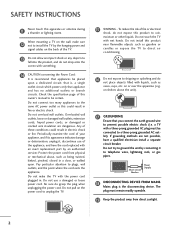
... rods, or gas pipes. on the power cord to dripping or splashing and do not expose this owner's manual to prevent possible electric shock (i.e. a TV with an exact replacement part by an authorized servicer. Do not try to ground the unit by the hanging power and signal cables on shelves...and the point where the cord exits the appliance. Protect the power cord from direct sunlight. 2 Do not make sure 12 not to install the TV by connecting it , discontinue use a damaged or loose power cord. To reduce the risk of these conditions could result in fire or electric shock. ...
... rods, or gas pipes. on the power cord to dripping or splashing and do not expose this owner's manual to prevent possible electric shock (i.e. a TV with an exact replacement part by an authorized servicer. Do not try to ground the unit by the hanging power and signal cables on shelves...and the point where the cord exits the appliance. Protect the power cord from direct sunlight. 2 Do not make sure 12 not to install the TV by connecting it , discontinue use a damaged or loose power cord. To reduce the risk of these conditions could result in fire or electric shock. ...
Owner's Manual (English)
Page 5
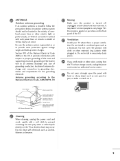
..., thinners or benzene. 3 Do not install in wire to an antenna discharge unit, size of grounding conductors, location of the TV. 23 Ventilation Install your TV where there is turned off, unplugged and all cables have been removed. Do not cover the product with cloth or other odors ...upon the panel with respect to proper grounding of the mast and supporting structure, grounding of overhead power lines or other liquids directly on the TV as a bookcase. Be sure the antenna system is installed, follow the precautions below. Do not press against voltage surges and built-up static...
..., thinners or benzene. 3 Do not install in wire to an antenna discharge unit, size of grounding conductors, location of the TV. 23 Ventilation Install your TV where there is turned off, unplugged and all cables have been removed. Do not cover the product with cloth or other odors ...upon the panel with respect to proper grounding of the mast and supporting structure, grounding of overhead power lines or other liquids directly on the TV as a bookcase. Be sure the antenna system is installed, follow the precautions below. Do not press against voltage surges and built-up static...
Owner's Manual (English)
Page 6
... 9 Stand Instruction 10 Cable Management 11 Desktop Pedestal Installation 12 Swivel Stand 12 Attaching the TV to a Desk 12 VESA Wall Mounting 13 Securing the TV to the wall to prevent falling when the TV is used on Discs 46 Selecting Language - Parental Control Setup 51 - User Mode 66 ...Setup 16 DVD Setup 19 VCR Setup 21 Other A/V Source Setup 23 Audio out Connection 24 PC Setup 25 WATCHING TV / CHANNEL CONTROL Remote Control Functions 32 Turning On TV 34 Channel Selection 34 Volume Adjustment 34 Quick Menu / Favorite Channel Setup 35 Initial Setting 36 On-Screen Menus ...
... 9 Stand Instruction 10 Cable Management 11 Desktop Pedestal Installation 12 Swivel Stand 12 Attaching the TV to a Desk 12 VESA Wall Mounting 13 Securing the TV to the wall to prevent falling when the TV is used on Discs 46 Selecting Language - Parental Control Setup 51 - User Mode 66 ...Setup 16 DVD Setup 19 VCR Setup 21 Other A/V Source Setup 23 Audio out Connection 24 PC Setup 25 WATCHING TV / CHANNEL CONTROL Remote Control Functions 32 Turning On TV 34 Channel Selection 34 Volume Adjustment 34 Quick Menu / Favorite Channel Setup 35 Initial Setting 36 On-Screen Menus ...
Owner's Manual (English)
Page 7
... Sleep Timer Setting 90 Auto Shut-off Setting 91 PARENTAL CONTROL / RATINGS Set Password & Lock System 92 Channel Blocking 95 Movie & TV Rating 96 Downloadable Rating 101 External Input Blocking 102 Key Lock 103 APPENDIX Troubleshooting 104 Maintenance 106 Product Specifications 107 Programing the Remote Control... 108 IR Code 111 External Control Through RS-232C 113 Open Source License 120 5 User Mode 77 Balance 78 TV Speakers On/Off Setup 79 Audio Reset 80 Stereo/SAP Broadcasts Setup 81 Audio Language 82 On-Screen Menus Language Selection 83 Caption ...
... Sleep Timer Setting 90 Auto Shut-off Setting 91 PARENTAL CONTROL / RATINGS Set Password & Lock System 92 Channel Blocking 95 Movie & TV Rating 96 Downloadable Rating 101 External Input Blocking 102 Key Lock 103 APPENDIX Troubleshooting 104 Maintenance 106 Product Specifications 107 Programing the Remote Control... 108 IR Code 111 External Control Through RS-232C 113 Open Source License 120 5 User Mode 77 Balance 78 TV Speakers On/Off Setup 79 Audio Reset 80 Stereo/SAP Broadcasts Setup 81 Audio Language 82 On-Screen Menus Language Selection 83 Caption ...
Owner's Manual (English)
Page 8
...under license from SRS Labs, Inc. TruSurround XT technology is turned on the screen, appearing as tiny red, green, or blue spots. I Avoid touching the LCD screen or holding your local authority. 6 Doing so may be authorized by U.S. This is normal, there is a trademark of Macrovision's copy protection technology in ... use of SRS Labs, Inc. However, they have no adverse effect on the screen. On Disposal (Only Hg lamp used LCD TV) The fluorescent lamp used in the product must be a small "flicker" when it for long periods of DVD format/Logo Licensing Corporation. Do not ...
...under license from SRS Labs, Inc. TruSurround XT technology is turned on the screen, appearing as tiny red, green, or blue spots. I Avoid touching the LCD screen or holding your local authority. 6 Doing so may be authorized by U.S. This is normal, there is a trademark of Macrovision's copy protection technology in ... use of SRS Labs, Inc. However, they have no adverse effect on the screen. On Disposal (Only Hg lamp used LCD TV) The fluorescent lamp used in the product must be a small "flicker" when it for long periods of DVD format/Logo Licensing Corporation. Do not ...
Owner's Manual (English)
Page 9
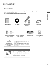
...When using the VGA (D-sub 15 pin cable) PC connection, the user must use shielded signal interface cables with your TV. Copyright© 2007 LGE, All Rights Reserved. PREPARATION ROTA ROTA PREPARATION ACCESSORIES Ensure that the following accessories are included... + VOL FAV 1DISPLAY MUTE REPEAT ZOOM 7 4 5 2 3 SUBTITLE A-B ANGLE 8 6 AUDIO TITLE MENU CH P A G E AV MODE 0 9 FLASHRBEKTURN RETURN ROTAT TV E- SLOW + EJECT 0 9 FLASHRBEKTURN SKIP + DISC MENU 1.5V 1.5V Owner's Manual CD Manual Remote Control, Batteries Power Cord x 4 x 4 Bolts for stand assembly ...
...When using the VGA (D-sub 15 pin cable) PC connection, the user must use shielded signal interface cables with your TV. Copyright© 2007 LGE, All Rights Reserved. PREPARATION ROTA ROTA PREPARATION ACCESSORIES Ensure that the following accessories are included... + VOL FAV 1DISPLAY MUTE REPEAT ZOOM 7 4 5 2 3 SUBTITLE A-B ANGLE 8 6 AUDIO TITLE MENU CH P A G E AV MODE 0 9 FLASHRBEKTURN RETURN ROTAT TV E- SLOW + EJECT 0 9 FLASHRBEKTURN SKIP + DISC MENU 1.5V 1.5V Owner's Manual CD Manual Remote Control, Batteries Power Cord x 4 x 4 Bolts for stand assembly ...
Owner's Manual (English)
Page 10
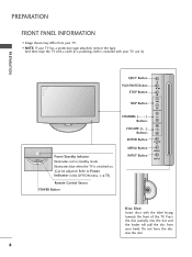
.../Standby Indicator Illuminates red in the OPTION menu. Press the disc partially into the slot. 8 Illuminates blue when the TV is included with the label facing towards the front of the TV. Do not force the disc into the slot and the loader will pull the disc from your... TV. I Image shown may differ from your hand. Refer to Power Indicator in standby mode. PREPARATION FRONT PANEL INFORMATION I NOTE: If your TV, use it). G p.73) Remote Control Sensor POWER Button CHANNEL ( , ) Buttons VOLUME (+, ...
.../Standby Indicator Illuminates red in the OPTION menu. Press the disc partially into the slot. 8 Illuminates blue when the TV is included with the label facing towards the front of the TV. Do not force the disc into the slot and the loader will pull the disc from your... TV. I Image shown may differ from your hand. Refer to Power Indicator in standby mode. PREPARATION FRONT PANEL INFORMATION I NOTE: If your TV, use it). G p.73) Remote Control Sensor POWER Button CHANNEL ( , ) Buttons VOLUME (+, ...
Owner's Manual (English)
Page 11
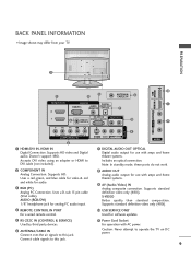
...). Note: In standby mode, these ports do not work. 2 COMPONENT IN Analog Connection. Connect cable signals to operate the TV on DC power. 9 BACK PANEL INFORMATION I Image shown may differ from your TV. R PREPARATION R 11 HDMI IN 3 SERVICE ONLY 10 USB 1 5 3 ANTENNA/ CABLE IN 6 HDMI/DVI IN RGB IN DIGITAL 1 RGB(PC...
...). Note: In standby mode, these ports do not work. 2 COMPONENT IN Analog Connection. Connect cable signals to operate the TV on DC power. 9 BACK PANEL INFORMATION I Image shown may differ from your TV. R PREPARATION R 11 HDMI IN 3 SERVICE ONLY 10 USB 1 5 3 ANTENNA/ CABLE IN 6 HDMI/DVI IN RGB IN DIGITAL 1 RGB(PC...
Owner's Manual (English)
Page 12
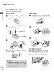
... push the tab aside. ! COVER BASE 3 Assemble the TV as shown. 3 Detach the stand from TV. 4 Fix the 4 bolts securely using the holes in the back of the TV. STAND BODY 2 Loose the bolts from your TV. NOTE G When assembling the desk type stand, make sure...for the stand. PREPARATION PREPARATION STAND INSTRUCTION I Image shown may differ from TV. INSTALLATION 1 Carefully place the TV screen side down on a cushioned surface to protect the screen from damage. DETACHMENT 1 Carefully place the TV screen side down on a cushioned surface to protect the screen from damage...
... push the tab aside. ! COVER BASE 3 Assemble the TV as shown. 3 Detach the stand from TV. 4 Fix the 4 bolts securely using the holes in the back of the TV. STAND BODY 2 Loose the bolts from your TV. NOTE G When assembling the desk type stand, make sure...for the stand. PREPARATION PREPARATION STAND INSTRUCTION I Image shown may differ from TV. INSTALLATION 1 Carefully place the TV screen side down on a cushioned surface to protect the screen from damage. DETACHMENT 1 Carefully place the TV screen side down on a cushioned surface to protect the screen from damage...

Owner's Manual (English)
Page 13
To connect additional equipment, see the EXTERNAL EQUIPMENT SETUP section. 11 ken by excessive pressure. 2 Connect the cables as shown. Note: This cable management clip can be bro- Turn the CABLE MANAGEMENT CLIP as necessary. PREPARATION CABLE MANAGEMENT I Image shown may differ from your TV. 1 Align the hole with the tab on the CABLE MANAGEMENT CLIP.
To connect additional equipment, see the EXTERNAL EQUIPMENT SETUP section. 11 ken by excessive pressure. 2 Connect the cables as shown. Note: This cable management clip can be bro- Turn the CABLE MANAGEMENT CLIP as necessary. PREPARATION CABLE MANAGEMENT I Image shown may differ from your TV. 1 Align the hole with the tab on the CABLE MANAGEMENT CLIP.
Owner's Manual (English)
Page 14
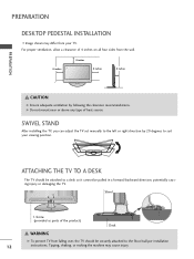
... cannot be pulled in a forward/backward direction, potentially causing injury or damaging the TV. For proper ventilation, allow a clearance of heat source. SWIVEL STAND After installing the TV, you can adjust the TV set manually to the left or right direction by following the clearance recommendations. PREPARATION ...shown may cause injury. G Do not mount near or above any type of 4 inches on all four sides from falling over, the TV should be securely attached to the floor/wall per installation 12 instructions. Tipping, shaking, or rocking the machine may differ from your viewing ...
... cannot be pulled in a forward/backward direction, potentially causing injury or damaging the TV. For proper ventilation, allow a clearance of heat source. SWIVEL STAND After installing the TV, you can adjust the TV set manually to the left or right direction by following the clearance recommendations. PREPARATION ...shown may cause injury. G Do not mount near or above any type of 4 inches on all four sides from falling over, the TV should be securely attached to the floor/wall per installation 12 instructions. Tipping, shaking, or rocking the machine may differ from your viewing ...
Owner's Manual (English)
Page 15
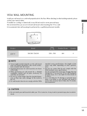
... Do not use an LG brand wall mount when mounting the TV to the instructions included with the VESA standard screw specifications. G LG is used . LG recommends that you use fasten the screws too strongly, this may cause damage to the inside to personal injury. A B Product LCD TV Model 26LG40, 32LG40 VESA (A * B) .... G Do not use screws longer then the standard dimension, as they may damage the TV or cause the TV to a fall and result in severe personal injury. LG is not liable for TV damage or personal injury when a non-VESA or non specified wall mount is not liable ...
... Do not use an LG brand wall mount when mounting the TV to the instructions included with the VESA standard screw specifications. G LG is used . LG recommends that you use fasten the screws too strongly, this may cause damage to the inside to personal injury. A B Product LCD TV Model 26LG40, 32LG40 VESA (A * B) .... G Do not use screws longer then the standard dimension, as they may damage the TV or cause the TV to a fall and result in severe personal injury. LG is not liable for TV damage or personal injury when a non-VESA or non specified wall mount is not liable ...
Owner's Manual (English)
Page 16
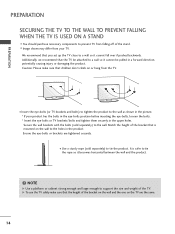
... to the wall. Ensure the eye-bolts or brackets are the same. 14 Secure the wall brackets with the bolts (sold separately) to prevent TV from the TV. It is mounted on the wall to tie the rope so it becomes horizontal between the wall and the product. ! PREPARATION PREPARATION SECURING THE... differ from your product has the bolts in the eye-bolts position before inserting the eye-bolts, loosen the bolts. * Insert the eye-bolts or TV brackets/bolts and tighten them securely in the upper holes. NOTE G Use a platform or cabinet strong enough and large enough to a wall so it cannot...
... to the wall. Ensure the eye-bolts or brackets are the same. 14 Secure the wall brackets with the bolts (sold separately) to prevent TV from the TV. It is mounted on the wall to tie the rope so it becomes horizontal between the wall and the product. ! PREPARATION PREPARATION SECURING THE... differ from your product has the bolts in the eye-bolts position before inserting the eye-bolts, loosen the bolts. * Insert the eye-bolts or TV brackets/bolts and tighten them securely in the upper holes. NOTE G Use a platform or cabinet strong enough and large enough to a wall so it cannot...
Owner's Manual (English)
Page 17
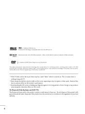
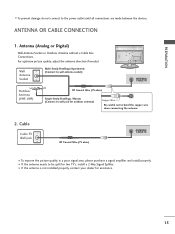
.../ CABLE IN Outdoor Antenna (VHF, UHF) 2. R PREPARATION R I To improve the picture quality in a poor signal area, please purchase a signal amplifier and install properly. Cable Cable TV Wall Jack RF Coaxial Wire (75 ohm) Single-family Dwellings /Houses (Connect to wall jack for two...
.../ CABLE IN Outdoor Antenna (VHF, UHF) 2. R PREPARATION R I To improve the picture quality in a poor signal area, please purchase a signal amplifier and install properly. Cable Cable TV Wall Jack RF Coaxial Wire (75 ohm) Single-family Dwellings /Houses (Connect to wall jack for two...
Owner's Manual (English)
Page 18
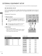
... shown below. How to connect 1 Connect the video outputs (Y, PB, PR) of the digital set-top box to the COMPONENT IN AUDIO jacks on the TV. 2. However, if you have finished connecting all equipment. RGB(PC) AUDIO A (RGB/DVI) 2 RS-232C 1 REMOTE (CONTROL & S CONTROL IN VIDEO AUDIO COMPONENT ...IN S-VIDEO ( ) 2 Connect the audio output of the digital settop box to the COMPONENT IN VIDEO jacks on the TV. EXTERNAL EQUIPMENT SETUP EXTERNAL EQUIPMENT SETUP I Turn on the digital set-top box. (Refer to the owner's manual for the digital set-top box...
... shown below. How to connect 1 Connect the video outputs (Y, PB, PR) of the digital set-top box to the COMPONENT IN AUDIO jacks on the TV. 2. However, if you have finished connecting all equipment. RGB(PC) AUDIO A (RGB/DVI) 2 RS-232C 1 REMOTE (CONTROL & S CONTROL IN VIDEO AUDIO COMPONENT ...IN S-VIDEO ( ) 2 Connect the audio output of the digital settop box to the COMPONENT IN VIDEO jacks on the TV. EXTERNAL EQUIPMENT SETUP EXTERNAL EQUIPMENT SETUP I Turn on the digital set-top box. (Refer to the owner's manual for the digital set-top box...
Owner's Manual (English)
Page 19
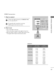
... digital set -top box to connect 1 Connect the digital set -top box.) I Select the HDMI1, HDMI2, or HDMI3 input source on the TV using the INPUT button on the TV. 2 No separate audio connection is necessary. How to HDMI/DVI IN1, 2, or 3 jack on the remote control. HDMI Connection 1. HDMI/DVI IN...
... digital set -top box to connect 1 Connect the digital set -top box.) I Select the HDMI1, HDMI2, or HDMI3 input source on the TV using the INPUT button on the TV. 2 No separate audio connection is necessary. How to HDMI/DVI IN1, 2, or 3 jack on the remote control. HDMI Connection 1. HDMI/DVI IN...
Owner's Manual (English)
Page 20
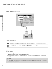
NOTE G A DVI to use I Select the HDMI 1, HDMI 2 or HDMI 3 input source on the TV using the INPUT button on the TV. 2. How to HDMI cable or adapter is necessary. 18 DVI doesn't support audio, so a separate audio connection is required for the digital set -top box ...to the HDMI/DVI IN1, 2, or 3 jack on the TV. 2 Connect the PC audio output to HDMI Connection HDMI/DVI IN 2 1 RGB IN DIGITAL RGB(PC) AUDIO AUDIO OU (RGB/DVI) OPTICA RS-232C IN...
NOTE G A DVI to use I Select the HDMI 1, HDMI 2 or HDMI 3 input source on the TV using the INPUT button on the TV. 2. How to HDMI cable or adapter is necessary. 18 DVI doesn't support audio, so a separate audio connection is required for the digital set -top box ...to the HDMI/DVI IN1, 2, or 3 jack on the TV. 2 Connect the PC audio output to HDMI Connection HDMI/DVI IN 2 1 RGB IN DIGITAL RGB(PC) AUDIO AUDIO OU (RGB/DVI) OPTICA RS-232C IN...


