
Owners Manual
Page 3
... relocate the receiving antenna. - Connect the equipment to the grounding system of the building, as practical. Any changes or modifications not expressly approved by turning the equipment off and on, the user is no guarantee that the cable ground shall be of sufficient magnitude to Article 820-40 of important operating and maintenance (servicing) instructions in a residential installation. The lightning flash with...
... relocate the receiving antenna. - Connect the equipment to the grounding system of the building, as practical. Any changes or modifications not expressly approved by turning the equipment off and on, the user is no guarantee that the cable ground shall be of sufficient magnitude to Article 820-40 of important operating and maintenance (servicing) instructions in a residential installation. The lightning flash with...
Owners Manual
Page 6
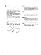
... (e.g.) plastic while plugged in Wire Electric Service Equipment NEC: National Electrical Code Antenna Discharge Unit (NEC Section 810-20) Grounding Conductors (NEC Section 810-21) Ground Clamps Power Service Grounding Electrode System (NEC Art 250, Part H) 21 Cleaning When cleaning, unplug the power cord and scrub gently with respect to proper grounding of the mast and supporting structure, grounding of...
... (e.g.) plastic while plugged in Wire Electric Service Equipment NEC: National Electrical Code Antenna Discharge Unit (NEC Section 810-20) Grounding Conductors (NEC Section 810-21) Ground Clamps Power Service Grounding Electrode System (NEC Art 250, Part H) 21 Cleaning When cleaning, unplug the power cord and scrub gently with respect to proper grounding of the mast and supporting structure, grounding of...

Owners Manual
Page 7
...Stand Installation 18 VESA Wall Mounting 19 Desktop Pedestal Installation 19 Antenna or Cable Connection 20 EXTERNAL EQUIPMENT SETUP HD Receiver Setup 21 DVD Setup 24 VCR Setup 26 Other A/V Source Setup 28 Digital Audio Output 28 PC Setup 29 WATCHING TV / CHANNEL CONTROL Remote Control Functions 32 Turning On TV 34 Channel Selection 34 Volume Adjustment 34 On-Screen Menus Selection 35 Channel Setup 36 - EZ Picture - EZ Picture - User Mode 48 XD - Black (Darkness) Level 51 Picture Reset 52 Low-Power Picture Mode 52 Image Sticking Minimization( ISM) Method 53 SOUND...
...Stand Installation 18 VESA Wall Mounting 19 Desktop Pedestal Installation 19 Antenna or Cable Connection 20 EXTERNAL EQUIPMENT SETUP HD Receiver Setup 21 DVD Setup 24 VCR Setup 26 Other A/V Source Setup 28 Digital Audio Output 28 PC Setup 29 WATCHING TV / CHANNEL CONTROL Remote Control Functions 32 Turning On TV 34 Channel Selection 34 Volume Adjustment 34 On-Screen Menus Selection 35 Channel Setup 36 - EZ Picture - EZ Picture - User Mode 48 XD - Black (Darkness) Level 51 Picture Reset 52 Low-Power Picture Mode 52 Image Sticking Minimization( ISM) Method 53 SOUND...

Owners Manual
Page 12
... TV is switched on . INPUT ENTER Illuminates green when the set is switched on . POWER Button INPUT Button MENU Button ENTER Button VOLUME Buttons CHANNEL Buttons 42PG60C, 42PG65C Stand (Only 42PG65C model) Remote Control Sensor POWER Button Power/Standby Indicator Illuminates red in standby mode. INPUT MENU ENTER VOL CH INPUT MENU ENTER VOL CH INPUT MENU ENTER VOL CH INPUT Button MENU Button ENTER Button VOLUME (-,+) Buttons CHANNEL (E, D) Buttons 10 INPUT MENU ENTER VOL CH Remote Control Sensor Power/Standby Indicator Illuminates red when the TV...
... TV is switched on . INPUT ENTER Illuminates green when the set is switched on . POWER Button INPUT Button MENU Button ENTER Button VOLUME Buttons CHANNEL Buttons 42PG60C, 42PG65C Stand (Only 42PG65C model) Remote Control Sensor POWER Button Power/Standby Indicator Illuminates red in standby mode. INPUT MENU ENTER VOL CH INPUT MENU ENTER VOL CH INPUT MENU ENTER VOL CH INPUT Button MENU Button ENTER Button VOLUME (-,+) Buttons CHANNEL (E, D) Buttons 10 INPUT MENU ENTER VOL CH Remote Control Sensor Power/Standby Indicator Illuminates red when the TV...

Owners Manual
Page 14
... the LCD TV models. PREPARATION ■ Here shown may be somewhat different from various types of equipment. S-VIDEO Connect S-Video out from an external device to either input. 2 DIGITAL AUDIO OUT Connect digital audio from your TV. AUDIO IN (RGB, DVI) Connect the audio from a PC or DTV. 7 SPEAKER OUT 8Ω 8 AV (Audio/Video) IN Connect audio/video output from an S-VIDEO device. 9 COMPONENT IN Connect a component video/audio device to this jack. 12 Note: In standby mode, these ports do not work. 3 13 M.P.I . 4 RESET 5 SERVICE ONLY REMOTE CONTROL UPDATE...
... the LCD TV models. PREPARATION ■ Here shown may be somewhat different from various types of equipment. S-VIDEO Connect S-Video out from an external device to either input. 2 DIGITAL AUDIO OUT Connect digital audio from your TV. AUDIO IN (RGB, DVI) Connect the audio from a PC or DTV. 7 SPEAKER OUT 8Ω 8 AV (Audio/Video) IN Connect audio/video output from an S-VIDEO device. 9 COMPONENT IN Connect a component video/audio device to this jack. 12 Note: In standby mode, these ports do not work. 3 13 M.P.I . 4 RESET 5 SERVICE ONLY REMOTE CONTROL UPDATE...

Owners Manual
Page 21
... INSTALLATION For proper ventilation, allow a clearance of 4inches on the wall mount used. PREPARATION VESA WALL MOUNTING This product accepts a VESA-compliant mounting interface pad. (optional) There 4 threaded holes are available for attaching the bracket. A B Product LCD TV PLASMA TV Model 32LC5DC*, 32LC50C*, 32LX5DC*, 32LX50C* 32/37/42LC5DC*, 32/37/42LC50C*, 42LB5DC, 42LB50C 42PG60C, 42PG65C 42PX8DC VESA (A * B) 200 * 100 600 * 400 400 * 400 600 * 400 NOTE G Screw length needed...
... INSTALLATION For proper ventilation, allow a clearance of 4inches on the wall mount used. PREPARATION VESA WALL MOUNTING This product accepts a VESA-compliant mounting interface pad. (optional) There 4 threaded holes are available for attaching the bracket. A B Product LCD TV PLASMA TV Model 32LC5DC*, 32LC50C*, 32LX5DC*, 32LX50C* 32/37/42LC5DC*, 32/37/42LC50C*, 42LB5DC, 42LB50C 42PG60C, 42PG65C 42PX8DC VESA (A * B) 200 * 100 600 * 400 400 * 400 600 * 400 NOTE G Screw length needed...

Owners Manual
Page 23
.../DVI, HDMI2 No Yes Yes Yes Yes 21 However, if you have finished connecting all equipment. ■ This part of the digital set-top box to the owner's manual for LCD TV models. HD RECEIVER SETUP This TV can receive Digital Over-the-air/Cable signals without an external digital set -top box. (Refer to 2 the COMPONENT IN AUDIO jacks on the set. HDMI/DVI IN 1(DVI) 1 2 DIGITAL AUDIO OUT (OPTICAL) 2 M.P.I. Match the jack colors (Y = green, PB = blue, and PR = red).
.../DVI, HDMI2 No Yes Yes Yes Yes 21 However, if you have finished connecting all equipment. ■ This part of the digital set-top box to the owner's manual for LCD TV models. HD RECEIVER SETUP This TV can receive Digital Over-the-air/Cable signals without an external digital set -top box. (Refer to 2 the COMPONENT IN AUDIO jacks on the set. HDMI/DVI IN 1(DVI) 1 2 DIGITAL AUDIO OUT (OPTICAL) 2 M.P.I. Match the jack colors (Y = green, PB = blue, and PR = red).

Owners Manual
Page 24
...EXTERNAL EQUIPMENT SETUP EXTERNAL EQUIPMENT SETUP When connecting HDMI cable 1. HDMI supports both audio and video. 2. HDMI/DVI IN 1(DVI) DIGITAL AUDIO OUT (OPTICAL) 2 M.P.I RJP INTERFACE 1 VIDEO AUDIO COMPONENT IN HDMI-DTV OUTPUT ( ) 22 NOTE G If the device does not support Auto HDMI, you need to the owner's manual for the digital set-top box.) ■ Select HDMI1/DVI or HDMI2 input source with using the INPUT button on the remote control. How to use ■ Turn on the set the output resolution appropriately. How to connect 1 Connect the digital set-top box to HDMI...
...EXTERNAL EQUIPMENT SETUP EXTERNAL EQUIPMENT SETUP When connecting HDMI cable 1. HDMI supports both audio and video. 2. HDMI/DVI IN 1(DVI) DIGITAL AUDIO OUT (OPTICAL) 2 M.P.I RJP INTERFACE 1 VIDEO AUDIO COMPONENT IN HDMI-DTV OUTPUT ( ) 22 NOTE G If the device does not support Auto HDMI, you need to the owner's manual for the digital set-top box.) ■ Select HDMI1/DVI or HDMI2 input source with using the INPUT button on the remote control. How to use ■ Turn on the set the output resolution appropriately. How to connect 1 Connect the digital set-top box to HDMI...

Owners Manual
Page 25
RESET UPDATE REMOTE CONTROL OUT SERVICE ONLY RGB IN RJP INTERFACE 1 VIDEO AUDIO COMPONENT IN S-VIDEO (MONO) AUDIO AV IN 1 VIDEO SPEAKER AUDIO OUT IN 8 (RGB, DVI) 2 DVI-DTV OUTPUT L R 1. How to use ■ Turn on the digital set-top box. (Refer to DVI cable HDMI/DVI IN 1(DVI) DIGITAL AUDIO OUT (OPTICAL) 2 M.P.I. EXTERNAL EQUIPMENT SETUP When connecting HDMI to the owner's manual for the digital set-top box.) ■ Select HDMI1/DVI or HDMI2 input source with using the INPUT button on the remote control. 23 How to connect 1 Connect the DVI...
RESET UPDATE REMOTE CONTROL OUT SERVICE ONLY RGB IN RJP INTERFACE 1 VIDEO AUDIO COMPONENT IN S-VIDEO (MONO) AUDIO AV IN 1 VIDEO SPEAKER AUDIO OUT IN 8 (RGB, DVI) 2 DVI-DTV OUTPUT L R 1. How to use ■ Turn on the digital set-top box. (Refer to DVI cable HDMI/DVI IN 1(DVI) DIGITAL AUDIO OUT (OPTICAL) 2 M.P.I. EXTERNAL EQUIPMENT SETUP When connecting HDMI to the owner's manual for the digital set-top box.) ■ Select HDMI1/DVI or HDMI2 input source with using the INPUT button on the remote control. 23 How to connect 1 Connect the DVI...

Owners Manual
Page 26
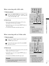
... AUDIO OUT (OPTICAL) 2 M.P.I. ■ Select Component input source with using the INPUT button on DVD player Y Y PB PR PB PR B-Y R-Y Cb Cr Pb Pr 24 Match the jack colors (Y = green, PB = blue, and PR = red). Y PB PR L R Connect the audio outputs of the DVD to the DVD player's manual for operating instructions. RJP ERFACE VIDEO AUDIO S-VIDEO ( ) COMPONENT IN Component Input ports To get better picture quality, connect a DVD player to use ■ Turn on the set . 2. Component ports on the TV Y Y Video output ports Y on the remote control...
... AUDIO OUT (OPTICAL) 2 M.P.I. ■ Select Component input source with using the INPUT button on DVD player Y Y PB PR PB PR B-Y R-Y Cb Cr Pb Pr 24 Match the jack colors (Y = green, PB = blue, and PR = red). Y PB PR L R Connect the audio outputs of the DVD to the DVD player's manual for operating instructions. RJP ERFACE VIDEO AUDIO S-VIDEO ( ) COMPONENT IN Component Input ports To get better picture quality, connect a DVD player to use ■ Turn on the set . 2. Component ports on the TV Y Y Video output ports Y on the remote control...

Owners Manual
Page 27
... DIGITAL AUDIO OUT (OPTICAL) 2 M.P.I . HDMI-DVD OUTPUT 25 When connecting with using the INPUT button on the set . S REMOTE CONTROL UPDATE OUT AUDIO NT IN S-VIDEO (MONO) AUDIO AV IN 1 VIDEO SPE O When connecting HDMI cable 1. HDMI supports both audio and video. 2. RJP INTERFACE VIDEO AUDIO COMPONENT IN 1 NOTE G If the device does not support Auto HDMI, you need to the AUDIO input jacks on the set . 2 No separated audio connection is necessary. S-VIDEO AUDIO L R EXTERNAL EQUIPMENT SETUP 2 Connect the audio outputs of the DVD to the S -VIDEO input...
... DIGITAL AUDIO OUT (OPTICAL) 2 M.P.I . HDMI-DVD OUTPUT 25 When connecting with using the INPUT button on the set . S REMOTE CONTROL UPDATE OUT AUDIO NT IN S-VIDEO (MONO) AUDIO AV IN 1 VIDEO SPE O When connecting HDMI cable 1. HDMI supports both audio and video. 2. RJP INTERFACE VIDEO AUDIO COMPONENT IN 1 NOTE G If the device does not support Auto HDMI, you need to the AUDIO input jacks on the set . 2 No separated audio connection is necessary. S-VIDEO AUDIO L R EXTERNAL EQUIPMENT SETUP 2 Connect the audio outputs of the DVD to the S -VIDEO input...
Owners Manual
Page 29
... jack colors (Video = yellow, Audio Left = white, and Audio Right = red) M.P.I. 2. How to connect M.P.I. 1 Connect the S-VIDEO output of the VCR to AV IN2, select A V 2 input source. ANT IN S-VIDEO L R VIDEO ANT OUT OUTPUT SWITCH 2 Connect the audio outputs of the VCR to connect 1 Connect the AUDIO/VIDEO jacks between TV and VCR. SER REMOTE CONTROL UPDATE OUT ■ Insert a video tape into the VCR and press PLAY on the VCR. (Refer to the VCR owner's manual.) ■ Select A V 1 input source with using the INPUT button...
... jack colors (Video = yellow, Audio Left = white, and Audio Right = red) M.P.I. 2. How to connect M.P.I. 1 Connect the S-VIDEO output of the VCR to AV IN2, select A V 2 input source. ANT IN S-VIDEO L R VIDEO ANT OUT OUTPUT SWITCH 2 Connect the audio outputs of the VCR to connect 1 Connect the AUDIO/VIDEO jacks between TV and VCR. SER REMOTE CONTROL UPDATE OUT ■ Insert a video tape into the VCR and press PLAY on the VCR. (Refer to the VCR owner's manual.) ■ Select A V 1 input source with using the INPUT button...
Owners Manual
Page 30
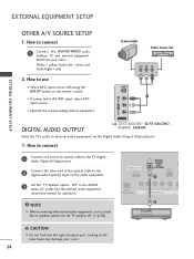
...'s audio to connect 1 Connect the AUDIO/VIDEO jacks between TV and external equipment. Looking at the laser beam may damage your vision. 28 Off " in the AUDIO menu. (G p.58). HDMI/DVI IN 1(DVI) DIGITAL AUDIO OUT (OPTICAL) 2 M.P.I. 1 ( RJP VIDEO AUDIO S-V NTERFACE COMPONENT IN 2 NOTE G When connecting with using the INPUT button on the audio equipment. 3 Set the "TV Speaker option - How to external audio equipment via the Digital Audio Output (Optical) port. 1. Match the jack colors. (Video = yellow, Audio Left = white, and Audio Right = red) Camcorder Video Game Set...
...'s audio to connect 1 Connect the AUDIO/VIDEO jacks between TV and external equipment. Looking at the laser beam may damage your vision. 28 Off " in the AUDIO menu. (G p.58). HDMI/DVI IN 1(DVI) DIGITAL AUDIO OUT (OPTICAL) 2 M.P.I. 1 ( RJP VIDEO AUDIO S-V NTERFACE COMPONENT IN 2 NOTE G When connecting with using the INPUT button on the audio equipment. 3 Set the "TV Speaker option - How to external audio equipment via the Digital Audio Output (Optical) port. 1. Match the jack colors. (Video = yellow, Audio Left = white, and Audio Right = red) Camcorder Video Game Set...
Owners Manual
Page 31
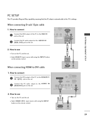
... INTERFACE VIDEO ER AUDIO COMPONENT IN (RGB, DVI) 2. EXTERNAL EQUIPMENT SETUP PC SETUP This TV provides Plug and Play capability, meaning that the PC adjusts automatically to use ( ) 1 ■ Turn on the PC and the set 2 ■ Select HDMI1/DVI input source with using the INPUT button on the remote control. When connecting D-sub 15pin cable 1. How to connect SERVICE ONLY REMOTE CONTROL ATE OUT ( ) ( ) RGB IN 1 Connect the RGB output of the PC to DVI cable RGB OUTPUT AUDIO 1. How...
... INTERFACE VIDEO ER AUDIO COMPONENT IN (RGB, DVI) 2. EXTERNAL EQUIPMENT SETUP PC SETUP This TV provides Plug and Play capability, meaning that the PC adjusts automatically to use ( ) 1 ■ Turn on the PC and the set 2 ■ Select HDMI1/DVI input source with using the INPUT button on the remote control. When connecting D-sub 15pin cable 1. How to connect SERVICE ONLY REMOTE CONTROL ATE OUT ( ) ( ) RGB IN 1 Connect the RGB output of the PC to DVI cable RGB OUTPUT AUDIO 1. How...

Owners Manual
Page 32
... the screen for Horizontal and Vertical frequencies is clear. The fixed image may not work if a HDMI to DVI Cable is in PC mode. If noise is present, change the PC output to another rate or adjust the brightness and contrast on the VIDEO menu until the picture is separate. G The synchronization input form for a long period of the PC graphic card. EXTERNAL EQUIPMENT SETUP Supported Display Specifications...
... the screen for Horizontal and Vertical frequencies is clear. The fixed image may not work if a HDMI to DVI Cable is in PC mode. If noise is present, change the PC output to another rate or adjust the brightness and contrast on the VIDEO menu until the picture is separate. G The synchronization input form for a long period of the PC graphic card. EXTERNAL EQUIPMENT SETUP Supported Display Specifications...

Owners Manual
Page 34
... etc. control buttons NUMBER button - (DASH) Used to enter a program number for type of program. WATCHING TV / CHANNEL CONTROL WATCHING TV / CHANNEL CONTROL REMOTE CONTROL FUNCTIONS When using the remote control, aim it at the remote control sensor on screen. G p.42 PIP INPUT Select the connected input source for the sub-picture. G p.41 Selects the factory preset picture depend on mode. External input modes rotate in regular sequence: TV, AV1INPUT 2, Component, RGB, HDMI1/DVI and HDMI2. G p.42 VCR/DVD Control video cassette recorders or DVD players. PIP Switches the sub picture Double...
... etc. control buttons NUMBER button - (DASH) Used to enter a program number for type of program. WATCHING TV / CHANNEL CONTROL WATCHING TV / CHANNEL CONTROL REMOTE CONTROL FUNCTIONS When using the remote control, aim it at the remote control sensor on screen. G p.42 PIP INPUT Select the connected input source for the sub-picture. G p.41 Selects the factory preset picture depend on mode. External input modes rotate in regular sequence: TV, AV1INPUT 2, Component, RGB, HDMI1/DVI and HDMI2. G p.42 VCR/DVD Control video cassette recorders or DVD players. PIP Switches the sub picture Double...

Owners Manual
Page 35
... Switch the sound on the back side and install the batteries matching correct polarity (+ with new ones. ■ Close cover. G p.43-44 CC Select a closed caption. INPUT ENTER ■ Use a INPUT TV POWER MODE TV INPUT DVD MULTI VCR PIP PIP CH - UP/DOWN PAGE Move from any menu. PIP CH + PIP INPUT EZ PIC EZ SOUND SWAP INFO CC EXIT MENU RATIO SAP ENTER VOL TIMER MUTE CH PAGE 1 2 3 remote control INPUT TV POWER MODE TV INPUT DVD MULTI VCR PIP PIP CH - INFO Display...
... Switch the sound on the back side and install the batteries matching correct polarity (+ with new ones. ■ Close cover. G p.43-44 CC Select a closed caption. INPUT ENTER ■ Use a INPUT TV POWER MODE TV INPUT DVD MULTI VCR PIP PIP CH - UP/DOWN PAGE Move from any menu. PIP CH + PIP INPUT EZ PIC EZ SOUND SWAP INFO CC EXIT MENU RATIO SAP ENTER VOL TIMER MUTE CH PAGE 1 2 3 remote control INPUT TV POWER MODE TV INPUT DVD MULTI VCR PIP PIP CH - INFO Display...

Owners Manual
Page 37
... use D E F G button to display the available menus. Manual config. Block Downloadable Rating SCREEN SETUP VIDEO AUDIO TIME OPTION SCREEN LOCK Auto config. SETUP SETUP VIDEO AUDIO TIME OPTION SCREEN LOCK EZ Scan Manual Scan Channel Edit DTV Signal Channel Label VIDEO SETUP VIDEO AUDIO TIME OPTION SCREEN LOCK EZ Picture Color Temperature XD Advanced Reset AUDIO SETUP Audio Language VIDEO EZ SoundRite AUDIO EZ Sound TIME Balance 0 OPTION TV Speakers SCREEN LOCK WATCHING TV / CHANNEL CONTROL LOCK For USA SETUP VIDEO AUDIO TIME OPTION SCREEN LOCK Lock System Set Password...
... use D E F G button to display the available menus. Manual config. Block Downloadable Rating SCREEN SETUP VIDEO AUDIO TIME OPTION SCREEN LOCK Auto config. SETUP SETUP VIDEO AUDIO TIME OPTION SCREEN LOCK EZ Scan Manual Scan Channel Edit DTV Signal Channel Label VIDEO SETUP VIDEO AUDIO TIME OPTION SCREEN LOCK EZ Picture Color Temperature XD Advanced Reset AUDIO SETUP Audio Language VIDEO EZ SoundRite AUDIO EZ Sound TIME Balance 0 OPTION TV Speakers SCREEN LOCK WATCHING TV / CHANNEL CONTROL LOCK For USA SETUP VIDEO AUDIO TIME OPTION SCREEN LOCK Lock System Set Password...

Owners Manual
Page 76
... the MENU button and then use the Movie Rating System (MPAA) only. Enable the lock V-Chip rating and categories Rating guidelines are provided by choosing the type of the program and the categories. Then, press the G button. ■ Enter the password as requested. ■ The TV is used to block specific channels, ratings, and external viewing sources. PARENTAL CONTROL / RATINGS Parental Control can be done: 1. The Parental Control Function (V-Chip) is set...
... the MENU button and then use the Movie Rating System (MPAA) only. Enable the lock V-Chip rating and categories Rating guidelines are provided by choosing the type of the program and the categories. Then, press the G button. ■ Enter the password as requested. ■ The TV is used to block specific channels, ratings, and external viewing sources. PARENTAL CONTROL / RATINGS Parental Control can be done: 1. The Parental Control Function (V-Chip) is set...

Owners Manual
Page 86
... be turned off. After blinking twice, this code is successful. 4 Press the MENU button to operate the device. If you have to repeat from step 2. 3 Enter the appropriate code from the code table on the mode button will be programmed to store the code. If not, steps 2-5. APPENDIX Remote Control Code DVD Brand Codes Brand APEX DIGITAL 022 DENON 020 014 GE 005 006 HARMAN KARDON 027 JVC 012 LG...
... be turned off. After blinking twice, this code is successful. 4 Press the MENU button to operate the device. If you have to repeat from step 2. 3 Enter the appropriate code from the code table on the mode button will be programmed to store the code. If not, steps 2-5. APPENDIX Remote Control Code DVD Brand Codes Brand APEX DIGITAL 022 DENON 020 014 GE 005 006 HARMAN KARDON 027 JVC 012 LG...


