
Specification (English)
Page 2
...In (Y,Pb,Pr) + L/R Audio 2 REar Audio/Video Inputs/Outputs (Continued) Digital Audio Out 2 (1 Coaxial/ 1 Optical) HDMI/HDCP Input 3 RGB In (D-Sub 15pin) - All other trademarks are the property of LG Corp. PC 1 PC Audio Input 1 RS-232c In (Control/Service) 1 Remote Control In...)-AUDIO-R AV IN 1 AV OUT VIDEO L/MONO -AUDIO- 32" CLASS LCD HDTV (31.5" diagonal) 31.7" 3.1" 32LB9D 7.9" 3.9" 24.4" 21.8" 11.2" 16.4" TV ATSC/NTSC/QAM Clear Tuner • Video Screen Size Class: 32" (31.5" Diagonal) Native Display Resolution 1366 x 768p Dynamic...
...In (Y,Pb,Pr) + L/R Audio 2 REar Audio/Video Inputs/Outputs (Continued) Digital Audio Out 2 (1 Coaxial/ 1 Optical) HDMI/HDCP Input 3 RGB In (D-Sub 15pin) - All other trademarks are the property of LG Corp. PC 1 PC Audio Input 1 RS-232c In (Control/Service) 1 Remote Control In...)-AUDIO-R AV IN 1 AV OUT VIDEO L/MONO -AUDIO- 32" CLASS LCD HDTV (31.5" diagonal) 31.7" 3.1" 32LB9D 7.9" 3.9" 24.4" 21.8" 11.2" 16.4" TV ATSC/NTSC/QAM Clear Tuner • Video Screen Size Class: 32" (31.5" Diagonal) Native Display Resolution 1366 x 768p Dynamic...
Owner's Manual (English)
Page 6
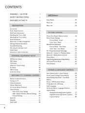
Auto Scan ( Auto Tuning 42 - Channel Editing 44 Input List 45 SimpLink 46 Input Label 48 4 MEDIAHOST MEDIAHOST Entry Modes 49 Photo List 50 Music List 54 PICTURE CONTROL Picture Size (Aspect Ratio) Control 56 Preset Picture ... 69 Sound Setting Adjustment - Analog Broadcasting System Captions . . . . 77 - Preset 57 - Picture Mode - User Mode 70 Balance 72 Stereo / SAP Broadcast Setup 73 TV Speakers On/ Off Setup 74 Audio Language 75 On-Screen Menus Language Selection 76 Caption Mode - Caption Option 80 CONTENTS WARNING / CAUTION 1 SAFETY INSTRUCTIONS 2 FEATURES...
Auto Scan ( Auto Tuning 42 - Channel Editing 44 Input List 45 SimpLink 46 Input Label 48 4 MEDIAHOST MEDIAHOST Entry Modes 49 Photo List 50 Music List 54 PICTURE CONTROL Picture Size (Aspect Ratio) Control 56 Preset Picture ... 69 Sound Setting Adjustment - Analog Broadcasting System Captions . . . . 77 - Preset 57 - Picture Mode - User Mode 70 Balance 72 Stereo / SAP Broadcast Setup 73 TV Speakers On/ Off Setup 74 Audio Language 75 On-Screen Menus Language Selection 76 Caption Mode - Caption Option 80 CONTENTS WARNING / CAUTION 1 SAFETY INSTRUCTIONS 2 FEATURES...
Owner's Manual (English)
Page 7
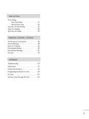
Auto Clock Setup 81 - TIME SETTING Clock Setting - Manual Clock Setup 82 Auto On/ Off Time Setting 83 Sleep Time Setting 84 Auto Shut-off Setting 85 PARENTAL CONTROL / RATINGS Set Password & Lock System 86 Channel Blocking 88 Movie & TV Rating 89 Downloadable Rating 89 External Input Blocking 92 Key Lock 92 APPENDIX Troubleshooting 93 Maintenance 95 Product Specifications 96 Programming the Remote Control 97 IR Codes 101 External Control through RS-232C 103 5
Auto Clock Setup 81 - TIME SETTING Clock Setting - Manual Clock Setup 82 Auto On/ Off Time Setting 83 Sleep Time Setting 84 Auto Shut-off Setting 85 PARENTAL CONTROL / RATINGS Set Password & Lock System 86 Channel Blocking 88 Movie & TV Rating 89 Downloadable Rating 89 External Input Blocking 92 Key Lock 92 APPENDIX Troubleshooting 93 Maintenance 95 Product Specifications 96 Programming the Remote Control 97 IR Codes 101 External Control through RS-232C 103 5

Owner's Manual (English)
Page 9
...LCD TV PLASMA TV Owner's Manual http://www.lgusa.com www.lg.ca Copyright© 2007 LGE, All Rights Reserved. For LCD TV models This feature is not available for stand assembly Refer to p. 18 2 - Bolts Refer to p. 18 Refer to p. 13 For PLASMA TV...with your plasma display. TV Brackets, 2- Please be different from the figures shown here. Wall Brackets Option Extras D-sub 15 pin Cable 32LB9D* only 1-Screw for ...p. 18 2- I The accessories can be cautions of the exterior. CD Manual TV INPUT STB BRIGHT - MENU BACK CC AUTO DEMO APM M/C EJECT RATIO SIMPLINK 1.5V...
...LCD TV PLASMA TV Owner's Manual http://www.lgusa.com www.lg.ca Copyright© 2007 LGE, All Rights Reserved. For LCD TV models This feature is not available for stand assembly Refer to p. 18 2 - Bolts Refer to p. 18 Refer to p. 13 For PLASMA TV...with your plasma display. TV Brackets, 2- Please be different from the figures shown here. Wall Brackets Option Extras D-sub 15 pin Cable 32LB9D* only 1-Screw for ...p. 18 2- I The accessories can be cautions of the exterior. CD Manual TV INPUT STB BRIGHT - MENU BACK CC AUTO DEMO APM M/C EJECT RATIO SIMPLINK 1.5V...
Owner's Manual (English)
Page 10
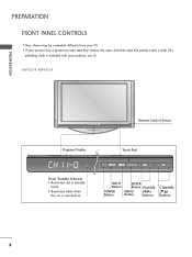
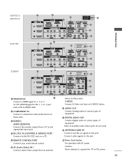
Power Standby Indicator • illuminates red in standby mode. • illuminates white when the set is included with your TV. And then wipe the product with a cloth (If a polishing cloth is switched on. PREPARATION FRONT PANEL CONTROLS I If your product has a protection tape attached, remove the tape. Touch Pad ENTER INPUT Button POWER Button ENTER Button VOLUME MENU Button (F,G) Buttons CHANNEL (E,D) Buttons 8 I Here shown may be somewhat different from your product, use it). 50PY3D/F, 60PY3D/F PREPARATION Remote Control Sensor Program Display . .
Power Standby Indicator • illuminates red in standby mode. • illuminates white when the set is included with your TV. And then wipe the product with a cloth (If a polishing cloth is switched on. PREPARATION FRONT PANEL CONTROLS I If your product has a protection tape attached, remove the tape. Touch Pad ENTER INPUT Button POWER Button ENTER Button VOLUME MENU Button (F,G) Buttons CHANNEL (E,D) Buttons 8 I Here shown may be somewhat different from your product, use it). 50PY3D/F, 60PY3D/F PREPARATION Remote Control Sensor Program Display . .

Owner's Manual (English)
Page 11
... • illuminates red in standby mode. • illuminates green when the set is switched on . 32LB9D* CH CH CHANNEL (E,D) ButtonsCH VOL VOLUME (F,G) Buttons VOL ENTER Button MENU Button VOL ENTER MENU INPUT /I ENTER Button MENU Button INPUT Button POWER Button Intelligent Eye Adjusts picture according to the surrounding conditions. PREPARATION 47LC7DF CH CHANNEL...
... • illuminates red in standby mode. • illuminates green when the set is switched on . 32LB9D* CH CH CHANNEL (E,D) ButtonsCH VOL VOLUME (F,G) Buttons VOL ENTER Button MENU Button VOL ENTER MENU INPUT /I ENTER Button MENU Button INPUT Button POWER Button Intelligent Eye Adjusts picture according to the surrounding conditions. PREPARATION 47LC7DF CH CHANNEL...
Owner's Manual (English)
Page 12
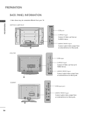
... from an external device to these jacks. 32LB9D* VIDEO L/MONO AUDIO R USB IN VIDEO L/MONO AUDIO R USB IN USB Input port AV INAV2 IN 2 AUDIO/VIDEO Input Connect audio/video output from an SVIDEO device. AUDIO/VIDEO Input Connect audio/video output from an external device...VIDEO L/MONO AUDIO R USB IN S-VIDEO AV IN 2 USB Input S-VIDEO Input Connect S-Video out from an external device to these jacks. 10 PREPARATION PREPARATION BACK PANEL INFORMATION I Here shown may be somewhat different from your TV. 50PY3D/F, 60PY3D/F VIDEVOIDLE/OMOL/NMOONAOUDAIUODIOR R UUSSBB AAVVININ2 2 SS-V-...
... from an external device to these jacks. 32LB9D* VIDEO L/MONO AUDIO R USB IN VIDEO L/MONO AUDIO R USB IN USB Input port AV INAV2 IN 2 AUDIO/VIDEO Input Connect audio/video output from an SVIDEO device. AUDIO/VIDEO Input Connect audio/video output from an external device...VIDEO L/MONO AUDIO R USB IN S-VIDEO AV IN 2 USB Input S-VIDEO Input Connect S-Video out from an external device to these jacks. 10 PREPARATION PREPARATION BACK PANEL INFORMATION I Here shown may be somewhat different from your TV. 50PY3D/F, 60PY3D/F VIDEVOIDLE/OMOL/NMOONAOUDAIUODIOR R UUSSBB AAVVININ2 2 SS-V-...
Owner's Manual (English)
Page 13
... cable signals to this jack. Power Cord Socket For operation with a DVI to the appropriate input port. Caution : Never attempt to this jack. ANTENNA/CABLE IN Connect over-the air signals to operate the TV on a PC. S-VIDEO Connect S-Video out from a PC to HDMI cable. AUDIO OUT...PREPARATION 50PY3D/F, 60PY3D/F RGB /DVI 47LC7DF RGB /DVI VIDEO L/MONO AUDIO R USB IN S-VIDEO ANTENNA/ CABLE IN AV IN 2 ANTENNA/ CABLE IN 32LB9D* RGB /DVI ANTENNA/ CABLE IN HDMI/DVI IN Connect a HDMI signal to various types of equipment. Note: In standby mode, these jacks.
... cable signals to this jack. Power Cord Socket For operation with a DVI to the appropriate input port. Caution : Never attempt to this jack. ANTENNA/CABLE IN Connect over-the air signals to operate the TV on a PC. S-VIDEO Connect S-Video out from a PC to HDMI cable. AUDIO OUT...PREPARATION 50PY3D/F, 60PY3D/F RGB /DVI 47LC7DF RGB /DVI VIDEO L/MONO AUDIO R USB IN S-VIDEO ANTENNA/ CABLE IN AV IN 2 ANTENNA/ CABLE IN 32LB9D* RGB /DVI ANTENNA/ CABLE IN HDMI/DVI IN Connect a HDMI signal to various types of equipment. Note: In standby mode, these jacks.

Owner's Manual (English)
Page 22
... box or other digital external device, refer to the COMPONENT IN AUDIO 1 jacks on the remote control. I If connected to COMPONENT IN 2 input, select COMPONENT 2 input source. Match the jack colors (Y = green, PB = blue, and PR = red). 2 Connect the audio output of EXTERNAL EQUIPMENT SETUP ... with using the INPUT button on the set . Y PB PR L R 1 2 2. I This part of the digital set -top box. When connecting Component cable 1. EXTERNAL EQUIPMENT SETUP EXTERNAL EQUIPMENT SETUP HD RECEIVER SETUP This TV can receive Digital Over-the-air/Cable signals without an external ...
... box or other digital external device, refer to the COMPONENT IN AUDIO 1 jacks on the remote control. I If connected to COMPONENT IN 2 input, select COMPONENT 2 input source. Match the jack colors (Y = green, PB = blue, and PR = red). 2 Connect the audio output of EXTERNAL EQUIPMENT SETUP ... with using the INPUT button on the set . Y PB PR L R 1 2 2. I This part of the digital set -top box. When connecting Component cable 1. EXTERNAL EQUIPMENT SETUP EXTERNAL EQUIPMENT SETUP HD RECEIVER SETUP This TV can receive Digital Over-the-air/Cable signals without an external ...

Owner's Manual (English)
Page 23
RGB 1 2 When connecting HDMI cable 1. How to use I Select HDMI1, HDMI2 or HDMI3 input source with using the INPUT button on the remote control. I Select RGB-PC input source with using the INPUT button on the remote control. How to use I Turn on the digital set-top box. (Refer to HDMI/DVI IN1, 2 or 3 jack...
RGB 1 2 When connecting HDMI cable 1. How to use I Select HDMI1, HDMI2 or HDMI3 input source with using the INPUT button on the remote control. I Select RGB-PC input source with using the INPUT button on the remote control. How to use I Turn on the digital set-top box. (Refer to HDMI/DVI IN1, 2 or 3 jack...

Owner's Manual (English)
Page 24
How to use I Turn on the digital set-top box. (Refer to the owner's manual for the digital set-top box.) I Select HDMI1, HDMI2 or HDMI3 input source with using the INPUT button on the set -top box to the AUDIO(RGB/DVI) jack on the remote control. 22 How to connect 1 Connect the DVI output of the digital set . 2. EXTERNAL EQUIPMENT SETUP When connecting HDMI to the HDMI/DVI IN1, 2 or 3 jack on the set. 2 Connect the audio output of the digital set-top box to DVI cable RGB 3 EXTERNAL EQUIPMENT SETUP 2 1 DVI-DTV OUTPUT L R 1.
How to use I Turn on the digital set-top box. (Refer to the owner's manual for the digital set-top box.) I Select HDMI1, HDMI2 or HDMI3 input source with using the INPUT button on the set -top box to the AUDIO(RGB/DVI) jack on the remote control. 22 How to connect 1 Connect the DVI output of the digital set . 2. EXTERNAL EQUIPMENT SETUP When connecting HDMI to the HDMI/DVI IN1, 2 or 3 jack on the set. 2 Connect the audio output of the digital set-top box to DVI cable RGB 3 EXTERNAL EQUIPMENT SETUP 2 1 DVI-DTV OUTPUT L R 1.

Owner's Manual (English)
Page 25
... with using the INPUT button on the DVD player, insert a DVD. Match the jack colors (Y = green, PB = blue, and PR = red). 2 Connect the audio outputs of the DVD to the DVD player's manual for operating instruc- Component ports on the TV Y PB PR Video output ports on the set .... 2. I Refer to the COMPONENT IN VIDEO1 jacks on DVD player Y PB PR Y Pb Pr Y B-Y R-Y Y Cb Cr 23 Y PB PR L R 1 2 Component Input ports To get better picture quality, connect a DVD ...
... with using the INPUT button on the DVD player, insert a DVD. Match the jack colors (Y = green, PB = blue, and PR = red). 2 Connect the audio outputs of the DVD to the DVD player's manual for operating instruc- Component ports on the TV Y PB PR Video output ports on the set .... 2. I Refer to the COMPONENT IN VIDEO1 jacks on DVD player Y PB PR Y Pb Pr Y B-Y R-Y Y Cb Cr 23 Y PB PR L R 1 2 Component Input ports To get better picture quality, connect a DVD ...

Owner's Manual (English)
Page 26
... output resolution appropriately. 24 1 HDMI-DVD OUTPUT I If the DVD does not support Auto HDMI, you need to use I Turn on the remote control. I Select A V 1 input source with an S-Video cable 1. How to connect 1 Connect the S-VIDEO output of the DVD to the S-VIDEO... input on the set. 2 Connect the audio outputs of the DVD to the AUDIO input jacks on the set . 2. How to connect 1 Connect the HDMI output of the DVD to the HDMI/DVI IN1, 2 or...
... output resolution appropriately. 24 1 HDMI-DVD OUTPUT I If the DVD does not support Auto HDMI, you need to use I Turn on the remote control. I Select A V 1 input source with an S-Video cable 1. How to connect 1 Connect the S-VIDEO output of the DVD to the S-VIDEO... input on the set. 2 Connect the audio outputs of the DVD to the AUDIO input jacks on the set . 2. How to connect 1 Connect the HDMI output of the DVD to the HDMI/DVI IN1, 2 or...

Owner's Manual (English)
Page 28
... that you have a mono VCR, connect the audio cable from the VCR to the AUDIO L/MONO jack of the VCR to normal composite (RCA cable) input. 2 Connect the audio outputs of the set. How to connect 1 Connect the S-VIDEO output of the VCR to the VCR owner's manual.) I Insert a video tape... into the VCR and press PLAY on the VCR. (Refer to the S V I If connected to connect 1 Connect the AUDIO/VIDEO jacks between TV and VCR. How to use I Insert a video tape into the VCR and press PLAY on the VCR. (Refer to AV IN 2, select...
... that you have a mono VCR, connect the audio cable from the VCR to the AUDIO L/MONO jack of the VCR to normal composite (RCA cable) input. 2 Connect the audio outputs of the set. How to connect 1 Connect the S-VIDEO output of the VCR to the VCR owner's manual.) I Insert a video tape... into the VCR and press PLAY on the VCR. (Refer to the S V I If connected to connect 1 Connect the AUDIO/VIDEO jacks between TV and VCR. How to use I Insert a video tape into the VCR and press PLAY on the VCR. (Refer to AV IN 2, select...

Owner's Manual (English)
Page 29
Match the jack colors. (Video = yellow, Audio Left = white, and Audio Right = red) 2. I If connected to connect 1 Connect the AUDIO/VIDEO jacks between TV and external equipment. I Select AV2 input source with using the INPUT button on the remote control. How to AV IN 1 input, select AV1 input source. EXTERNAL EQUIPMENT SETUP OTHER A/V SOURCE SETUP USB IN VIDEO L/MONO AUDIO R S-VIDEO 1 AV IN 2 VIDEO L R Camcorder Video Game Set 1. How to use I Operate the corresponding external equipment. 27
Match the jack colors. (Video = yellow, Audio Left = white, and Audio Right = red) 2. I If connected to connect 1 Connect the AUDIO/VIDEO jacks between TV and external equipment. I Select AV2 input source with using the INPUT button on the remote control. How to AV IN 1 input, select AV1 input source. EXTERNAL EQUIPMENT SETUP OTHER A/V SOURCE SETUP USB IN VIDEO L/MONO AUDIO R S-VIDEO 1 AV IN 2 VIDEO L R Camcorder Video Game Set 1. How to use I Operate the corresponding external equipment. 27

Owner's Manual (English)
Page 30
When connecting D-sub 15 pin cable 1. If the refresh rate of the PC graphic card can not be noise associated with using the INPUT button on the remote control. RGB OUTPUT AUDIO 28 I Turn on the PC and the set . 2. RGB 1 2 NOTE G Check the image on the VIDEO...the AUDIO (RGB/DVI) jack on the set . How to the TV's settings. EXTERNAL EQUIPMENT SETUP EXTERNAL EQUIPMENT SETUP PC SETUP This TV provides Plug and Play capability, meaning that the PC adjusts automatically to use I Select RGB-PC input source with the resolution, vertical pattern, contrast or brightness in PC mode...
When connecting D-sub 15 pin cable 1. If the refresh rate of the PC graphic card can not be noise associated with using the INPUT button on the remote control. RGB OUTPUT AUDIO 28 I Turn on the PC and the set . 2. RGB 1 2 NOTE G Check the image on the VIDEO...the AUDIO (RGB/DVI) jack on the set . How to the TV's settings. EXTERNAL EQUIPMENT SETUP EXTERNAL EQUIPMENT SETUP PC SETUP This TV provides Plug and Play capability, meaning that the PC adjusts automatically to use I Select RGB-PC input source with the resolution, vertical pattern, contrast or brightness in PC mode...

Owner's Manual (English)
Page 31
When connecting HDMI to use I Turn on the PC and the set I Select HDMI1, HDMI2 or HDMI3 input source with using the INPUT button on the set. 2. How to DVI cable RGB EXTERNAL EQUIPMENT SETUP 1 2 1. To get the best picture quality, adjust the output resolution of the PC ... audio output to the AUDIO(RGB/DVI) jack on the remote control. G If the PC does not support Auto DVI, you need to 1920x1080, 60Hz. (32LB9D* model: 1360x768, 60Hz) 29
When connecting HDMI to use I Turn on the PC and the set I Select HDMI1, HDMI2 or HDMI3 input source with using the INPUT button on the set. 2. How to DVI cable RGB EXTERNAL EQUIPMENT SETUP 1 2 1. To get the best picture quality, adjust the output resolution of the PC ... audio output to the AUDIO(RGB/DVI) jack on the remote control. G If the PC does not support Auto DVI, you need to 1920x1080, 60Hz. (32LB9D* model: 1360x768, 60Hz) 29

Owner's Manual (English)
Page 32
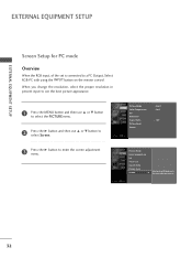
...on the screen for Horizontal and Vertical frequencies is present, change the PC output to another rate or adjust the brightness and contrast on your TV. EXTERNAL EQUIPMENT SETUP 30 The fixed image may not work if a HDMI to another resolution, change the PC graphic card or consult the manufacturer... of time. There may be changed, change the refresh rate to DVI Cable is clear. G The synchronization input form for a long period of the PC graphic card. G Check the image on the PICTURE menu until the picture is in PC mode.
...on the screen for Horizontal and Vertical frequencies is present, change the PC output to another rate or adjust the brightness and contrast on your TV. EXTERNAL EQUIPMENT SETUP 30 The fixed image may not work if a HDMI to another resolution, change the PC graphic card or consult the manufacturer... of time. There may be changed, change the refresh rate to DVI Cable is clear. G The synchronization input form for a long period of the PC graphic card. G Check the image on the PICTURE menu until the picture is in PC mode.
Owner's Manual (English)
Page 34
EXTERNAL EQUIPMENT SETUP EXTERNAL EQUIPMENT SETUP Screen Setup for PC mode Overview When the RGB input, of the set is connected to the screen adjustment menu. 32 Picture Mode Color Temperature XD Advanced Aspect Ratio Picture Reset Screen : User1 : Cool : 16:9 Picture Mode Color Temperature XD Advanced Aspect Ratio Picture Reset Screen G ...
EXTERNAL EQUIPMENT SETUP EXTERNAL EQUIPMENT SETUP Screen Setup for PC mode Overview When the RGB input, of the set is connected to the screen adjustment menu. 32 Picture Mode Color Temperature XD Advanced Aspect Ratio Picture Reset Screen : User1 : Cool : 16:9 Picture Mode Color Temperature XD Advanced Aspect Ratio Picture Reset Screen G ...

Owner's Manual (English)
Page 37
EXTERNAL EQUIPMENT SETUP AUDIO OUT SETUP Send the TV's audio to the TV's AUDIO OUT jacks 1 2 Set the "TV Speaker option - NOTE G When connecting with ACP(Audio Copy Protection) function. 1 2 ...the SPDIF out(optical/coaxial) about the contents with external audio equipment, such as amplifers or speakers, please turn the TV speakers off. (G p.74) CAUTION G Do not look into the optical output port. How to connect Analog L...vision. Digital 1 Connect one end of the optical or coaxial cable to the TV's OPTICAL or COAXIAL port of DIGITAL AUDIO OUT. 2 Connect the other end of the optical...
EXTERNAL EQUIPMENT SETUP AUDIO OUT SETUP Send the TV's audio to the TV's AUDIO OUT jacks 1 2 Set the "TV Speaker option - NOTE G When connecting with ACP(Audio Copy Protection) function. 1 2 ...the SPDIF out(optical/coaxial) about the contents with external audio equipment, such as amplifers or speakers, please turn the TV speakers off. (G p.74) CAUTION G Do not look into the optical output port. How to connect Analog L...vision. Digital 1 Connect one end of the optical or coaxial cable to the TV's OPTICAL or COAXIAL port of DIGITAL AUDIO OUT. 2 Connect the other end of the optical...


