
User Guide
Page 1
USER GUIDE Wood & Glass TV Stand for TVs up to 75" NS-HWG1865 SAFETY INFORMATION AND SPECIFICATIONS .2 PACKAGE CONTENTS: PARTS 3 PACKAGE CONTENTS: HARDWARE 4 ASSEMBLY INSTRUCTIONS 6 CARE AND MAINTENANCE 21 Before using your new product, please read these instructions to prevent any damage.
USER GUIDE Wood & Glass TV Stand for TVs up to 75" NS-HWG1865 SAFETY INFORMATION AND SPECIFICATIONS .2 PACKAGE CONTENTS: PARTS 3 PACKAGE CONTENTS: HARDWARE 4 ASSEMBLY INSTRUCTIONS 6 CARE AND MAINTENANCE 21 Before using your new product, please read these instructions to prevent any damage.
User Guide
Page 2
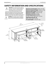
... each side of the television must be a choking hazard if swallowed. Keep these items away from young children! Maximum overall weight: 335 lbs (151.9 kg) Maximum top panel weight: 135 lbs (61.2 kg) Maximum shelf weight: 50 lbs (22.6 kg) Maximum TV weight: 135 lbs (61.2 kg) Maximum screen size: 75" diag. NS-HWG1865 SAFETY INFORMATION AND SPECIFICATIONS CAUTION: The console's top...
... each side of the television must be a choking hazard if swallowed. Keep these items away from young children! Maximum overall weight: 335 lbs (151.9 kg) Maximum top panel weight: 135 lbs (61.2 kg) Maximum shelf weight: 50 lbs (22.6 kg) Maximum TV weight: 135 lbs (61.2 kg) Maximum screen size: 75" diag. NS-HWG1865 SAFETY INFORMATION AND SPECIFICATIONS CAUTION: The console's top...

User Guide
Page 3
B Left side panel (1) C Right side panel (1) D Partition panel (1) F Front skirting (1) H Left skirting (1) I Right skirting (1) E Bottom shelf (1) G Back skirting (1) J Back panel (1) K Adjustable shelf (2) L Door (4) M Wood door panel (4) www.insigniaproducts.com 3 Tools needed: Wood & Glass TV Stand Hammer Phillips screwdriver Rubber mallet 3/8" drill bit Power drill PACKAGE CONTENTS: PARTS Make sure that you have all the parts necessary to the top panel. A Top panel (1) Note: Keep the stopper template attached to assemble your new TV stand.
B Left side panel (1) C Right side panel (1) D Partition panel (1) F Front skirting (1) H Left skirting (1) I Right skirting (1) E Bottom shelf (1) G Back skirting (1) J Back panel (1) K Adjustable shelf (2) L Door (4) M Wood door panel (4) www.insigniaproducts.com 3 Tools needed: Wood & Glass TV Stand Hammer Phillips screwdriver Rubber mallet 3/8" drill bit Power drill PACKAGE CONTENTS: PARTS Make sure that you have all the parts necessary to the top panel. A Top panel (1) Note: Keep the stopper template attached to assemble your new TV stand.
User Guide
Page 4
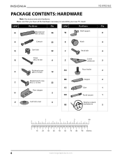
... necessary to assemble your new TV stand. Label Hardware N Wood dowel M8 x 30 mm 26 W Shelf support NS-HWG1865 Qty. 8 P Cam pin 22 X Knob 4 Q Cam lock 22 Y Knob bolt 4 Screw R M4 x 50 mm 6 Z Corner connector 2 S Flat head screw M3.5 x 15 mm 12 AA BB Washer head screw T M3.5 x 15 mm 22 CC Door stopper U 2 DD V Cam lock cover 6 EE Floor leveler...
... necessary to assemble your new TV stand. Label Hardware N Wood dowel M8 x 30 mm 26 W Shelf support NS-HWG1865 Qty. 8 P Cam pin 22 X Knob 4 Q Cam lock 22 Y Knob bolt 4 Screw R M4 x 50 mm 6 Z Corner connector 2 S Flat head screw M3.5 x 15 mm 12 AA BB Washer head screw T M3.5 x 15 mm 22 CC Door stopper U 2 DD V Cam lock cover 6 EE Floor leveler...

User Guide
Page 5
Wood & Glass TV Stand INSTALLATION TIPS Gluing wood dowels (N) When using a wood dowel (N), put one drop of a cam pin (P) is not threaded. Cam pin PANEL Pre-drilled hole Cam lock LOCKED PANEL Cam lock cover www.insigniaproducts.com 5 Insert the wood dowel (N), then gently tap it with a screwdriver to conceal. Before you... sure that the hole in the cam lock (Q) faces the outside edge of the part being used and into the cam lock hole, then rotate the cam lock (Q) clockwise with a rubber mallet to secure it screws into the cross slot of the cam lock (Q) to lock the cam pin (P)...
Wood & Glass TV Stand INSTALLATION TIPS Gluing wood dowels (N) When using a wood dowel (N), put one drop of a cam pin (P) is not threaded. Cam pin PANEL Pre-drilled hole Cam lock LOCKED PANEL Cam lock cover www.insigniaproducts.com 5 Insert the wood dowel (N), then gently tap it with a screwdriver to conceal. Before you... sure that the hole in the cam lock (Q) faces the outside edge of the part being used and into the cam lock hole, then rotate the cam lock (Q) clockwise with a rubber mallet to secure it screws into the cross slot of the cam lock (Q) to lock the cam pin (P)...
User Guide
Page 6
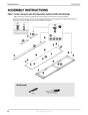
NS-HWG1865 ASSEMBLY INSTRUCTIONS Step 1: Screw cam pins onto the top panel, bottom shelf, and skirtings Tip: Assemble your stand on a carpeted floor or the empty TV stand carton to avoid scratching it. • Securely screw the cam pins (P) into the designated small holes on the top panel (A), bottom shelf (E), front skirting (F) and side skirtings (H and I) using a Phillips screwdriver. You'll need: P (22) Phillips screwdriver 6 www.insigniaproducts.com
NS-HWG1865 ASSEMBLY INSTRUCTIONS Step 1: Screw cam pins onto the top panel, bottom shelf, and skirtings Tip: Assemble your stand on a carpeted floor or the empty TV stand carton to avoid scratching it. • Securely screw the cam pins (P) into the designated small holes on the top panel (A), bottom shelf (E), front skirting (F) and side skirtings (H and I) using a Phillips screwdriver. You'll need: P (22) Phillips screwdriver 6 www.insigniaproducts.com
User Guide
Page 8
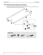
NS-HWG1865 Step 3: Attach the front skirting to the side skirtings 1 Glue two wood dowels (N) into the drilled holes on the front skirting (F). 2 Attach the front skirting (F) to the side skirtings (H and I) by inserting two cam locks (Q) and tightening with a screwdriver. Make sure that the cam screw holes face inward. You'll need: N (2) Q (2) CC (1) Phillips screwdriver 8 www.insigniaproducts.com
NS-HWG1865 Step 3: Attach the front skirting to the side skirtings 1 Glue two wood dowels (N) into the drilled holes on the front skirting (F). 2 Attach the front skirting (F) to the side skirtings (H and I) by inserting two cam locks (Q) and tightening with a screwdriver. Make sure that the cam screw holes face inward. You'll need: N (2) Q (2) CC (1) Phillips screwdriver 8 www.insigniaproducts.com
User Guide
Page 10
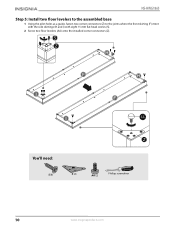
AA You'll need: S (8) Z (2) AA (2) Phillips screwdriver 10 www.insigniaproducts.com NS-HWG1865 Step 5: Install two floor levelers to the assembled base 1 Using the pilot holes as a guide, fasten two corner connectors (Z) to the joints where the front skirting (F) meet with the side skirtings (H and I) with eight 15 mm flat head screws (S). 2 Screw two floor levelers (AA) onto the installed corner connectors (Z).
AA You'll need: S (8) Z (2) AA (2) Phillips screwdriver 10 www.insigniaproducts.com NS-HWG1865 Step 5: Install two floor levelers to the assembled base 1 Using the pilot holes as a guide, fasten two corner connectors (Z) to the joints where the front skirting (F) meet with the side skirtings (H and I) with eight 15 mm flat head screws (S). 2 Screw two floor levelers (AA) onto the installed corner connectors (Z).
User Guide
Page 11
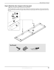
Wood & Glass TV Stand Step 6: Attach two door stoppers to the top panel Note: Keep the stopper template attached to the top panel (A). • Using the pilot holes as a guide, attach two door stoppers (U) onto the front supports on the top panel (A) with two 15 mm flat head screws (S) per stopper. You'll need: S (4) Phillips screwdriver U (2) www.insigniaproducts.com 11 Make sure that the right angle sides of the stoppers face the front of the unit.
Wood & Glass TV Stand Step 6: Attach two door stoppers to the top panel Note: Keep the stopper template attached to the top panel (A). • Using the pilot holes as a guide, attach two door stoppers (U) onto the front supports on the top panel (A) with two 15 mm flat head screws (S) per stopper. You'll need: S (4) Phillips screwdriver U (2) www.insigniaproducts.com 11 Make sure that the right angle sides of the stoppers face the front of the unit.
User Guide
Page 12
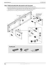
NS-HWG1865 Step 7: Align and attach the side panels to the top panel 1 Glue two wood dowels (N) into the holes on the top edge of the unit You'll need: N (4) Q (4) CC (1) Phillips screwdriver 12 www.insigniaproducts.com Make sure that the door hinge mounts are on the opposite end. Door stopper Door hinge mounts point towards the front of the left side panel (B). 2 Attach the left side panel to attach the right side panel (C) on the same side as the door stoppers. 3 Repeat this process to the top panel (A) by inserting two cam locks (Q) and tightening with a screwdriver.
NS-HWG1865 Step 7: Align and attach the side panels to the top panel 1 Glue two wood dowels (N) into the holes on the top edge of the unit You'll need: N (4) Q (4) CC (1) Phillips screwdriver 12 www.insigniaproducts.com Make sure that the door hinge mounts are on the opposite end. Door stopper Door hinge mounts point towards the front of the left side panel (B). 2 Attach the left side panel to attach the right side panel (C) on the same side as the door stoppers. 3 Repeat this process to the top panel (A) by inserting two cam locks (Q) and tightening with a screwdriver.

User Guide
Page 13
Door hinge mounting bases point towards the front of the partion panel (D). 2 Attach the partition panel to the top panel (A) by inserting two cam locks (Q) and tightening with a screwdriver. Wood & Glass TV Stand Step 8: Attach the partition panel to the top panel 1 Glue two wood dowels (N) into the inner holes on the top edge of the unit You'll need: N (2) Q (2) CC (1) Phillips screwdriver www.insigniaproducts.com 13
Door hinge mounting bases point towards the front of the partion panel (D). 2 Attach the partition panel to the top panel (A) by inserting two cam locks (Q) and tightening with a screwdriver. Wood & Glass TV Stand Step 8: Attach the partition panel to the top panel 1 Glue two wood dowels (N) into the inner holes on the top edge of the unit You'll need: N (2) Q (2) CC (1) Phillips screwdriver www.insigniaproducts.com 13
User Guide
Page 14
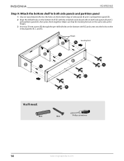
... bottom shelf (E) and screw into the holes on the bottom edge of side panels (B and C) and partition panel (D). 2 Align the drilled holes on the bottom shelf (E) with the installed wood dowels (N) on the vertical panels (B, C, and D). Hinges Leveling feet You'll need: N (6) R (6) Phillips screwdriver 14 www.insigniaproducts.com NS-HWG1865 Step 9: Attach the bottom shelf to both side panels and partition panel...
... bottom shelf (E) and screw into the holes on the bottom edge of side panels (B and C) and partition panel (D). 2 Align the drilled holes on the bottom shelf (E) with the installed wood dowels (N) on the vertical panels (B, C, and D). Hinges Leveling feet You'll need: N (6) R (6) Phillips screwdriver 14 www.insigniaproducts.com NS-HWG1865 Step 9: Attach the bottom shelf to both side panels and partition panel...

User Guide
Page 15
... is facing up. 3 Unfold the back panel (J) and align its holes with the pilot holes along the edges of the assembled unit. 4 Use the washer head screws (T) to secure the back panel to the assembled console frame 1 Go back and tighten all the parts are tight and there are no gaps between... the pieces. This will help keep the unit square. 2 Turn the assembled unit over so that all cam locks and screws. You'll need: T (22) Phillips screwdriver www.insigniaproducts.com 15 Wood & Glass TV Stand Step 10: Attach the back panel to the assembled...
... is facing up. 3 Unfold the back panel (J) and align its holes with the pilot holes along the edges of the assembled unit. 4 Use the washer head screws (T) to secure the back panel to the assembled console frame 1 Go back and tighten all the parts are tight and there are no gaps between... the pieces. This will help keep the unit square. 2 Turn the assembled unit over so that all cam locks and screws. You'll need: T (22) Phillips screwdriver www.insigniaproducts.com 15 Wood & Glass TV Stand Step 10: Attach the back panel to the assembled...

User Guide
Page 16
Make sure that you place the shelf supports at the same level so the shelves are not tilted. 4 Tilt and rest the adjustable shelves (K) onto the shelf supports (W). You'll need: V (6) W (8) 16 www.insigniaproducts.com NS-HWG1865 Step 11: Attach adjustable shelves 1 Stand the assembled unit upright. 2 Insert the cam lock covers (V) into the cross slots on the visible cam locks on the vertical panels (B, C, and D). 3 Insert eight shelf supports (W) into the holes in the sides of the compartments.
Make sure that you place the shelf supports at the same level so the shelves are not tilted. 4 Tilt and rest the adjustable shelves (K) onto the shelf supports (W). You'll need: V (6) W (8) 16 www.insigniaproducts.com NS-HWG1865 Step 11: Attach adjustable shelves 1 Stand the assembled unit upright. 2 Insert the cam lock covers (V) into the cross slots on the visible cam locks on the vertical panels (B, C, and D). 3 Insert eight shelf supports (W) into the holes in the sides of the compartments.

User Guide
Page 17
...Tip: If you need : Push in the back of the hinge arm to secure it to the mounting base. If necessary, adjust the screws on the knobs (X). 2 Attach a door (L) to the right side panel (C) by engaging both door hinges together as shown: A Extend both hinges of the door (L) ... side panel (B) and partition panel (D). x 4 Mounting base Hinge arm Release lever You'll need to remove a door, press the release lever on the ends of the mounting bases. Wood & Glass TV Stand Step 12: Attach doors to the vertical panels 1 Push the knob bolts (Y) through the inside of each door (L), then screw on ...
...Tip: If you need : Push in the back of the hinge arm to secure it to the mounting base. If necessary, adjust the screws on the knobs (X). 2 Attach a door (L) to the right side panel (C) by engaging both door hinges together as shown: A Extend both hinges of the door (L) ... side panel (B) and partition panel (D). x 4 Mounting base Hinge arm Release lever You'll need to remove a door, press the release lever on the ends of the mounting bases. Wood & Glass TV Stand Step 12: Attach doors to the vertical panels 1 Push the knob bolts (Y) through the inside of each door (L), then screw on ...
User Guide
Page 18
...BB) to help adhesion. 2 On the back of your stand. NS-HWG1865 Step 13: Attach the stopper to remove the stopper template. Press down on the stopper (BB) to help adhesion. 4 Repeat this process to "Step 14: Change the door panel" on top of the top panel (A), carefully pull out the thumb tacks to the top... prevent your TV from tipping, you must follow these instructions if you place a TV on page 19. If your TV has one of your TV has two bases: 1 On the back of the top panel (A), carefully pull out the thumb tacks to remove the stopper template. 2 Align the template at the position ...
...BB) to help adhesion. 2 On the back of your stand. NS-HWG1865 Step 13: Attach the stopper to remove the stopper template. Press down on the stopper (BB) to help adhesion. 4 Repeat this process to "Step 14: Change the door panel" on top of the top panel (A), carefully pull out the thumb tacks to the top... prevent your TV from tipping, you must follow these instructions if you place a TV on page 19. If your TV has one of your TV has two bases: 1 On the back of the top panel (A), carefully pull out the thumb tacks to remove the stopper template. 2 Align the template at the position ...

User Guide
Page 19
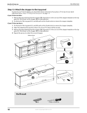
Otherwise, skip to "Step 15: Position the TV stand and install the tipping restraint hardware kit" on page 20. 1 Open a door (L) and loosen the screws on the inside of the door frame. 2 Rotate the clips to remove the old panel. 3 Insert the new panel, then rotate the clips and tighen screws to secure the panel in the door frame. 4 Repeat this...
Otherwise, skip to "Step 15: Position the TV stand and install the tipping restraint hardware kit" on page 20. 1 Open a door (L) and loosen the screws on the inside of the door frame. 2 Rotate the clips to remove the old panel. 3 Insert the new panel, then rotate the clips and tighen screws to secure the panel in the door frame. 4 Repeat this...

User Guide
Page 20
... do this could result in your TV stand falling forward, resulting in damage to the wall and the stand. NS-HWG1865 Step 15: Position the TV stand and install the tipping restraint hardware kit 1 Position the assembled stand against the wall where you plan to use it. 2 Adjust the leveling feet to level the TV stand. 3 Follow the instructions printed on the bag containing the...
... do this could result in your TV stand falling forward, resulting in damage to the wall and the stand. NS-HWG1865 Step 15: Position the TV stand and install the tipping restraint hardware kit 1 Position the assembled stand against the wall where you plan to use it. 2 Adjust the leveling feet to level the TV stand. 3 Follow the instructions printed on the bag containing the...
User Guide
Page 21
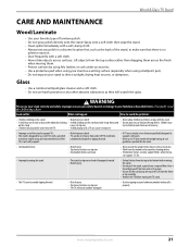
... frequently with the stand. • A child may on furniture specifically designed to support a television. • Never use with TVs with a soft, damp cloth. • Always test any other object by using felt, leather, or cork under accessories. • Use a protective pad when using the top shelf. Look out for: What can happen: How to avoid the problem: • Children climbing...
... frequently with the stand. • A child may on furniture specifically designed to support a television. • Never use with TVs with a soft, damp cloth. • Always test any other object by using felt, leather, or cork under accessories. • Use a protective pad when using the top shelf. Look out for: What can happen: How to avoid the problem: • Children climbing...

User Guide
Page 22
... web site. Contact Insignia: For customer service please call 1-866-BESTBUY. Where is packaged with the Product. AA, AAA, C etc.) • Products where the factory applied serial number has been altered or removed • Loss or Theft of Best Buy and its sole option): (1) repair the Product with new or rebuilt comparable products or parts. INSIGNIA SHALL NOT BE...
... web site. Contact Insignia: For customer service please call 1-866-BESTBUY. Where is packaged with the Product. AA, AAA, C etc.) • Products where the factory applied serial number has been altered or removed • Loss or Theft of Best Buy and its sole option): (1) repair the Product with new or rebuilt comparable products or parts. INSIGNIA SHALL NOT BE...

