Instruction Manual
Page 3
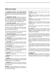
...transceiver's surfaces. NEVER touch the transceiver top cover when transmitting continuously for long period of the transceiver. R NEVER block any problems caused by unauthorized internal adjustment. ally desire to rain, snow or any liquids. AVOID placing the transceiver in excessively dusty environments... AVOID using or storing the transceiver in an electric shock or damage to the IC-7800 may be hot. AVOID placing the transceiver against continuous high volume operation. Use Icom microphones only (supplied or optional). The top cover may damage the transceiver or ...
...transceiver's surfaces. NEVER touch the transceiver top cover when transmitting continuously for long period of the transceiver. R NEVER block any problems caused by unauthorized internal adjustment. ally desire to rain, snow or any liquids. AVOID placing the transceiver in excessively dusty environments... AVOID using or storing the transceiver in an electric shock or damage to the IC-7800 may be hot. AVOID placing the transceiver against continuous high volume operation. Use Icom microphones only (supplied or optional). The top cover may damage the transceiver or ...

Instruction Manual
Page 22
... EXT MAX1A METER KEYPAD KEY RELAY ALC ALC ADJ B ACC 2 ACC 1 A ACC 2 ACC 1 E X T- Activated by voltage applied to prevent electrical shocks, TVI, BCI and other problems. y CIRCUIT BREAKER Cuts off the AC input when over-current occurs.
... EXT MAX1A METER KEYPAD KEY RELAY ALC ALC ADJ B ACC 2 ACC 1 A ACC 2 ACC 1 E X T- Activated by voltage applied to prevent electrical shocks, TVI, BCI and other problems. y CIRCUIT BREAKER Cuts off the AC input when over-current occurs.
Instruction Manual
Page 28
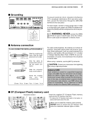
... Standing Wave Ratio (VSWR) for transmitting. Low SWR allows full power for your transceiver from lightning by using 1 antenna, use the [ANT1] connector. The IC-7800 has an SWR meter to protect the final transistors. NEVER insert or remove the CF memory card when the read/write indicator lights or blinks... or strap to install the memory card correctly. 2 INSTALLATION AND CONNECTIONS I Grounding To prevent electrical shock, television interference (TVI), broadcast interference (BCI) and other problems, ground the transceiver through the GROUND terminal on and solder it.
... Standing Wave Ratio (VSWR) for transmitting. Low SWR allows full power for your transceiver from lightning by using 1 antenna, use the [ANT1] connector. The IC-7800 has an SWR meter to protect the final transistors. NEVER insert or remove the CF memory card when the read/write indicator lights or blinks... or strap to install the memory card correctly. 2 INSTALLATION AND CONNECTIONS I Grounding To prevent electrical shock, television interference (TVI), broadcast interference (BCI) and other problems, ground the transceiver through the GROUND terminal on and solder it.

Instruction Manual
Page 29
... MAIN Ground (p. 2-3) Use the heaviest gauge wire or strap available and make the connection as short as possible. Grounding prevents electrical shocks, TVI and other problems. Straight key AC outlet R WARNING: Use the supplied AC power cable only. 2-4 2 INSTALLATION AND CONNECTIONS I /O 10MHz -10dBm DC OUT 15V EXT MAX1A METER KEYPAD KEY...
... MAIN Ground (p. 2-3) Use the heaviest gauge wire or strap available and make the connection as short as possible. Grounding prevents electrical shocks, TVI and other problems. Straight key AC outlet R WARNING: Use the supplied AC power cable only. 2-4 2 INSTALLATION AND CONNECTIONS I /O 10MHz -10dBm DC OUT 15V EXT MAX1A METER KEYPAD KEY...
Instruction Manual
Page 173
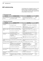
...for the operating p. 10-2 frequency. • Push [TUNER] for 1 sec. 13 MAINTENANCE I Troubleshooting The following chart is designed to help you correct problems which are • Push [SPLIT] and/or [DUALWATCH] to turn the pgs. 5-16, activated. the speaker. • The squelch is closed. &#... CAUSE Power does not come out from • Volume level is not properly tuned. • Rotate [RF PWR] clockwise. If you nearest Icom Dealer or Service Center. p. 3-9 tening level. • Turn [SQL] to 10 o'clock position to open the p. 3-9 squelch. • Push [TRANSMIT] to...
...for the operating p. 10-2 frequency. • Push [TUNER] for 1 sec. 13 MAINTENANCE I Troubleshooting The following chart is designed to help you correct problems which are • Push [SPLIT] and/or [DUALWATCH] to turn the pgs. 5-16, activated. the speaker. • The squelch is closed. &#... CAUSE Power does not come out from • Volume level is not properly tuned. • Rotate [RF PWR] clockwise. If you nearest Icom Dealer or Service Center. p. 3-9 tening level. • Turn [SQL] to 10 o'clock position to open the p. 3-9 squelch. • Push [TRANSMIT] to...

Instruction Manual
Page 174
MAINTENANCE 13 D Scanning PROBLEM POSSIBLE CAUSE SOLUTION REF. not stop. • Set [SQL] to comfortable tension level while turning the dial continuously and evenly in scan edge p. 8-4 not start ... select channels. p. 13-7 I Voice synthesizer operation [SPEECH] for main [SPEECH] for sub The IC-7800 has built-in level set mode. (p. 12-5) 13-3 Slide the brake adjustment to the threshold point. Programmed scan does • Squelch is activated. D Display PROBLEM POSSIBLE CAUSE The displayed frequency • The dial lock function is open. memory...
MAINTENANCE 13 D Scanning PROBLEM POSSIBLE CAUSE SOLUTION REF. not stop. • Set [SQL] to comfortable tension level while turning the dial continuously and evenly in scan edge p. 8-4 not start ... select channels. p. 13-7 I Voice synthesizer operation [SPEECH] for main [SPEECH] for sub The IC-7800 has built-in level set mode. (p. 12-5) 13-3 Slide the brake adjustment to the threshold point. Programmed scan does • Squelch is activated. D Display PROBLEM POSSIBLE CAUSE The displayed frequency • The dial lock function is open. memory...


