Instruction Manual
Page 1
THE TRANSCEIVER i7800 Instruction Manual A-6328H-1EX-u Printed in Japan © 2004-2006 Icom Inc.
THE TRANSCEIVER i7800 Instruction Manual A-6328H-1EX-u Printed in Japan © 2004-2006 Icom Inc.
Instruction Manual
Page 2
...INSTRUCTION MANUAL. You are registered trademarks of personal injury, fire or electric shock. IC-7800. FOREWORD Congratulations! We would like to take a few moments of your time to operate the transceiver. tempting to thank you agree with years of +40 dBm (HF bands only),..., and hope you for making the IC-7800 your IC-7800. No risk of Icom Incorporated (Japan) in Baudot RTTY and PSK31 modulator/demodulator and direct PC keyboard connection capability for the IC-7800. The IC-7800 is designed and built with Icom's superior technology and craftsmanship. Equipment damage...
...INSTRUCTION MANUAL. You are registered trademarks of personal injury, fire or electric shock. IC-7800. FOREWORD Congratulations! We would like to take a few moments of your time to operate the transceiver. tempting to thank you agree with years of +40 dBm (HF bands only),..., and hope you for making the IC-7800 your IC-7800. No risk of Icom Incorporated (Japan) in Baudot RTTY and PSK31 modulator/demodulator and direct PC keyboard connection capability for the IC-7800. The IC-7800 is designed and built with Icom's superior technology and craftsmanship. Equipment damage...
Instruction Manual
Page 3
... to operate this device under FCC regulations. ally desire to carry, lift or turn over the transceiver. This may reduce transceiver performance and/or damage to the IC-7800 may be damaged. If you experience a ringing in a place without adequate ventilation. The LCD display...internal antenna connector during transmission. tings of LCD displays. Avoid extension cords. Use Icom microphones only (supplied or optional). The transceiver weighs approx. 25 kg (55 lb). R NEVER operate or touch the transceiver with temperatures below ±0°C (+32°F) or above +50°C...
... to operate this device under FCC regulations. ally desire to carry, lift or turn over the transceiver. This may reduce transceiver performance and/or damage to the IC-7800 may be damaged. If you experience a ringing in a place without adequate ventilation. The LCD display...internal antenna connector during transmission. tings of LCD displays. Avoid extension cords. Use Icom microphones only (supplied or optional). The transceiver weighs approx. 25 kg (55 lb). R NEVER operate or touch the transceiver with temperatures below ±0°C (+32°F) or above +50°C...
Instruction Manual
Page 9
...Changing the file name 12-27 I Deleting a file 12-28 I Formatting the CF card 12-28 Section 13 MAINTENANCE I Troubleshooting 13-2 D Transceiver power 13-2 D Transmit and receive 13-2 D Scanning 13-3 D Display 13-3 I Main dial brake adjustment 13-3 I Voice synthesizer operation ...13-3 I SWR reading 13-4 I Screen type and font selections 13-4 I Frequency calibration (approximate 13-5 I Opening the transceiver's case 13-6 I Clock backup battery replacement 13-6 I Fuse replacement 13-7 I Resetting the CPU 13-7 I About protection indications 13-8 I ...
...Changing the file name 12-27 I Deleting a file 12-28 I Formatting the CF card 12-28 Section 13 MAINTENANCE I Troubleshooting 13-2 D Transceiver power 13-2 D Transmit and receive 13-2 D Scanning 13-3 D Display 13-3 I Main dial brake adjustment 13-3 I Voice synthesizer operation ...13-3 I SWR reading 13-4 I Screen type and font selections 13-4 I Frequency calibration (approximate 13-5 I Opening the transceiver's case 13-6 I Clock backup battery replacement 13-6 I Fuse replacement 13-7 I Resetting the CPU 13-7 I About protection indications 13-8 I ...
Instruction Manual
Page 12
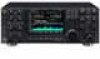
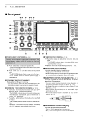
...10149; Enters timer set mode. (p. 4-12) • A straight key jack is switched ON. to turn the transceiver power OFF. • The [POWER] indicator lights orange when the transceiver is OFF when the internal power supply is located on the rear panel. w TRANSMIT SWITCH [TRANSMIT] Selects transmitting ... the squelch is bypassed automatically after 20 sec. See [KEY] on the rear panel. (p. 3-2) ➥ Push to turn the transceiver power ON. • The [POWER] indicator above this switch lights green when powered ON. ➥ Push for microphone connector information. 1-2
...10149; Enters timer set mode. (p. 4-12) • A straight key jack is switched ON. to turn the transceiver power OFF. • The [POWER] indicator lights orange when the transceiver is OFF when the internal power supply is located on the rear panel. w TRANSMIT SWITCH [TRANSMIT] Selects transmitting ... the squelch is bypassed automatically after 20 sec. See [KEY] on the rear panel. (p. 3-2) ➥ Push to turn the transceiver power ON. • The [POWER] indicator above this switch lights green when powered ON. ➥ Push for microphone connector information. 1-2
Instruction Manual
Page 13
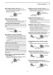
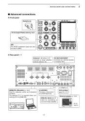
...Insert the supplied CF (Compact Flash) memory card for both reading/storing a wide variety of the transceiver's information and data. • The indicator beside the slot lights or blinks when the transceiver reads or writes to the memory card. • Push the eject button to receive when you ...gain increases !7 DRIVE GAIN CONTROL [DRIVE] (p. 3-13) Adjusts the transmitter level at the driver stage. to -receive switching delay time for an Icom microphone Decreases Increases !0 VOX/BREAK-IN SWITCH [VOX/BK-IN] ➥ Push to turn the VOX function ON and OFF during CW mode operation...
...Insert the supplied CF (Compact Flash) memory card for both reading/storing a wide variety of the transceiver's information and data. • The indicator beside the slot lights or blinks when the transceiver reads or writes to the memory card. • Push the eject button to receive when you ...gain increases !7 DRIVE GAIN CONTROL [DRIVE] (p. 3-13) Adjusts the transmitter level at the driver stage. to -receive switching delay time for an Icom microphone Decreases Increases !0 VOX/BREAK-IN SWITCH [VOX/BK-IN] ➥ Push to turn the VOX function ON and OFF during CW mode operation...
Instruction Manual
Page 20
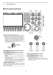
... [PBT CLEAR] (for the PBT function. The RIT or ∂TX functions must be ON. • The shift frequency range is the PBT control? This transceiver uses the DSP circuit for MAIN band; p. 5-12) *4 PBT CLEAR SWITCH [PBT CLEAR] (for SUB band;
... [PBT CLEAR] (for the PBT function. The RIT or ∂TX functions must be ON. • The shift frequency range is the PBT control? This transceiver uses the DSP circuit for MAIN band; p. 5-12) *4 PBT CLEAR SWITCH [PBT CLEAR] (for SUB band;
Instruction Manual
Page 23
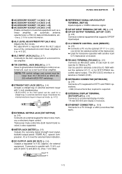
... via the optional CT-17 CI-V LEVEL CONVERTER for external control of the transceiver. ➥ Used for transceive operation with another Icom CI-V transceiver or receiver. #1 RS-232C TERMINAL [RS-232C] (p. 2-5) Connects an RS-232C cable, D-sub 9-pin to connect the IC-7800 to a PC. No adjustment is required when the ALC output level of the...
... via the optional CT-17 CI-V LEVEL CONVERTER for external control of the transceiver. ➥ Used for transceive operation with another Icom CI-V transceiver or receiver. #1 RS-232C TERMINAL [RS-232C] (p. 2-5) Connects an RS-232C cable, D-sub 9-pin to connect the IC-7800 to a PC. No adjustment is required when the ALC output level of the...
Instruction Manual
Page 26
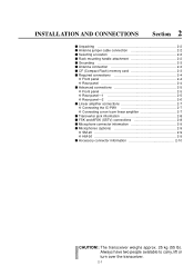
... 2-5 D Front panel 2-5 D Rear panel-1 2-5 D Rear panel-2 2-6 I Linear amplifier connections 2-7 D Connecting the IC-PW1 2-7 D Connecting a non-Icom linear amplifier 2-7 I Transverter jack information 2-8 I FSK and AFSK (SSTV) connections 2-8 I Microphone connector information 2-9 I Microphones (options 2-9 D SM-20 2-9 D HM-36 2-9 I Accessory connector information 2-10 CAUTION!: The transceiver weighs approx. 25 kg (55 lb). Always have two people available...
... 2-5 D Front panel 2-5 D Rear panel-1 2-5 D Rear panel-2 2-6 I Linear amplifier connections 2-7 D Connecting the IC-PW1 2-7 D Connecting a non-Icom linear amplifier 2-7 I Transverter jack information 2-8 I FSK and AFSK (SSTV) connections 2-8 I Microphone connector information 2-9 I Microphones (options 2-9 D SM-20 2-9 D HM-36 2-9 I Accessory connector information 2-10 CAUTION!: The transceiver weighs approx. 25 kg (55 lb). Always have two people available...
Instruction Manual
Page 27
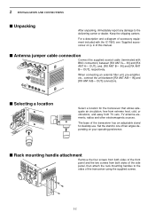
...cold, or vibrations, and away from both sides of the side panel, then attach the rack mounting handles to the sides of the transceiver using the supplied screws. 2-2 I Unpacking After unpacking, immediately report any damage to one of two angles depending on p. For a... ANT A/B- Keep the shipping cartons. OUT], and, [RX ANT B- I Antenna jumper cable connection Connect the supplied coaxial cable (terminated with the IC-7800, see 'Supplied accessories' on your operating preference. IN] and [RX ANT A- 2 INSTALLATION AND CONNECTIONS I Rack mounting handle attachment Remove the four...
...cold, or vibrations, and away from both sides of the side panel, then attach the rack mounting handles to the sides of the transceiver using the supplied screws. 2-2 I Unpacking After unpacking, immediately report any damage to one of two angles depending on p. For a... ANT A/B- Keep the shipping cartons. OUT], and, [RX ANT B- I Antenna jumper cable connection Connect the supplied coaxial cable (terminated with the IC-7800, see 'Supplied accessories' on your operating preference. IN] and [RX ANT A- 2 INSTALLATION AND CONNECTIONS I Rack mounting handle attachment Remove the four...
Instruction Manual
Page 28
... band. 2 INSTALLATION AND CONNECTIONS I Grounding To prevent electrical shock, television interference (TVI), broadcast interference (BCI) and other problems, ground the transceiver through the GROUND terminal on and solder it. For best results, connect a heavy gauge wire or strap to install the memory card correctly....solder solder Strip the cable as shown at left . Select antenna(s), such as possible. Antenna SWR Each antenna is of -range. The IC-7800 has an SWR meter to a gas or electric pipe, since the connection could cause an explosion or electric shock. r Screw the ...
... band. 2 INSTALLATION AND CONNECTIONS I Grounding To prevent electrical shock, television interference (TVI), broadcast interference (BCI) and other problems, ground the transceiver through the GROUND terminal on and solder it. For best results, connect a heavy gauge wire or strap to install the memory card correctly....solder solder Strip the cable as shown at left . Select antenna(s), such as possible. Antenna SWR Each antenna is of -range. The IC-7800 has an SWR meter to a gas or electric pipe, since the connection could cause an explosion or electric shock. r Screw the ...
Instruction Manual
Page 30
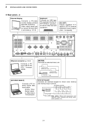
...also be input to [REMOTE]. [X-VERTER] Connects a transverter for V/UHF band use. [RELAY], [ALC] (p.2-7) Used for computer control and transceive operation. The optional CT-17 is required when connecting a PC to [MIC]. SP SUB MAIN [REMOTE], [RS-232C] (p. 14-2) Used for connecting... a non-Icom linear amplifier. E X T- ACC sockets (pgs.2-8, 2-10) External speaker (p. 15-4) SP-20 (option) 2-5 D Rear panel- 1 Antenna 1, 2, 3, 4 (p. 2-7) Connects a linear amplifier, ...
...also be input to [REMOTE]. [X-VERTER] Connects a transverter for V/UHF band use. [RELAY], [ALC] (p.2-7) Used for computer control and transceive operation. The optional CT-17 is required when connecting a PC to [MIC]. SP SUB MAIN [REMOTE], [RS-232C] (p. 14-2) Used for connecting... a non-Icom linear amplifier. E X T- ACC sockets (pgs.2-8, 2-10) External speaker (p. 15-4) SP-20 (option) 2-5 D Rear panel- 1 Antenna 1, 2, 3, 4 (p. 2-7) Connects a linear amplifier, ...
Instruction Manual
Page 31
...;5% ±5% ±5% S1 S2 S3 S4 (T1/M1) (T2/M2) (T3/M3) (T4/M4) Mute switch: Mutes both transmission and reception when switched ON during transceive operation, etc. 2-6 2 INSTALLATION AND CONNECTIONS D Rear panel- 2 External Display Connects a PC-style monitor display (at least 800×600 resolution). Video output signal can be...
...;5% ±5% ±5% S1 S2 S3 S4 (T1/M1) (T2/M2) (T3/M3) (T4/M4) Mute switch: Mutes both transmission and reception when switched ON during transceive operation, etc. 2-6 2 INSTALLATION AND CONNECTIONS D Rear panel- 2 External Display Connects a PC-style monitor display (at least 800×600 resolution). Video output signal can be...

Instruction Manual
Page 32
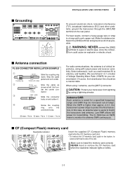
... ANT1 ANT2 REMOTE GND IC-PW1/EURO AC outlet Ground (Non-European versions: 100-120/220-240 V European version : 230 V) Transceiver *Optional D Connecting a non-Icom linear amplifier To an antenna ANT1 RELAY 50 Ω coaxial cable Transceiver ALC RF OUTPUT RF INPUT SEND ALC Non-Icom linear amplifier R WARNING: Set the transceiver output power and linear...
... ANT1 ANT2 REMOTE GND IC-PW1/EURO AC outlet Ground (Non-European versions: 100-120/220-240 V European version : 230 V) Transceiver *Optional D Connecting a non-Icom linear amplifier To an antenna ANT1 RELAY 50 Ω coaxial cable Transceiver ALC RF OUTPUT RF INPUT SEND ALC Non-Icom linear amplifier R WARNING: Set the transceiver output power and linear...
Instruction Manual
Page 37
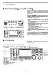
...power, make sure all programmed contents in memory channels and returns programmed values in the figure below. [DELAY] [NR] : Max. Then, reset the transceiver using the following procedure. w While pushing and holding [F-INP•ENT] and [MW], push [POWER] to turn power ON. • The CPU... is complete. counter- clockwise [RF] : Max. clockwise [MONI GAIN], [COMP], [DRIVE], [VOX GAIN], [ANTI VOX] : 12 o'clock After resetting the transceiver, set mode settings after turning power ON. counter clockwise [KEY SPEED] : 10-12 o'clock [NB] : Max. e Change the set controls as shown in set...
...power, make sure all programmed contents in memory channels and returns programmed values in the figure below. [DELAY] [NR] : Max. Then, reset the transceiver using the following procedure. w While pushing and holding [F-INP•ENT] and [MW], push [POWER] to turn power ON. • The CPU... is complete. counter- clockwise [RF] : Max. clockwise [MONI GAIN], [COMP], [DRIVE], [VOX GAIN], [ANTI VOX] : 12 o'clock After resetting the transceiver, set mode settings after turning power ON. counter clockwise [KEY SPEED] : 10-12 o'clock [NB] : Max. e Change the set controls as shown in set...

Instruction Manual
Page 40
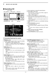
... the band key. • Push [MAIN] or [SUB] to select the band. If the dial lock function is always available for convenient frequency tuning. The transceiver has a keypad for details) ✔ CONVENIENT! e Input the desired frequency • Push [GENE•.] to sub. In this case, push [LOCK] to set the desired... desired band key on the keypad 1-3 times. • 3 different frequencies can be selected on each band with the keypad Keypad [EXAMPLE] 7.00000 MHz Push The transceiver has several tuning methods for tuning the sub band.
... the band key. • Push [MAIN] or [SUB] to select the band. If the dial lock function is always available for convenient frequency tuning. The transceiver has a keypad for details) ✔ CONVENIENT! e Input the desired frequency • Push [GENE•.] to sub. In this case, push [LOCK] to set the desired... desired band key on the keypad 1-3 times. • 3 different frequencies can be selected on each band with the keypad Keypad [EXAMPLE] 7.00000 MHz Push The transceiver has several tuning methods for tuning the sub band.
Instruction Manual
Page 51
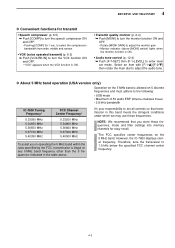
However, the IC-7800 displays carrier frequency. Therefore, tune the transceiver to adjust the audio tone. NOTE: We recommend that transmission in operating the 5 MHz band within the rules specified by the FCC, transmission is ON. &#...-4) ➥ Push [F-7•SET] then [F-1•LEVEL] to the following: • USB mode • Maximum of 50 watts ERP (Effective Radiated Power) • 2.8 kHz bandwidth IC-7800 Tuning Frequency* 5.33050 MHz 5.34650 MHz 5.36650 MHz 5.37150 MHz 5.40350 MHz FCC Channel Center Frequency* 5.33200 MHz 5.34800 MHz 5.36800 MHz 5.37300 MHz 5.40500...
However, the IC-7800 displays carrier frequency. Therefore, tune the transceiver to adjust the audio tone. NOTE: We recommend that transmission in operating the 5 MHz band within the rules specified by the FCC, transmission is ON. &#...-4) ➥ Push [F-7•SET] then [F-1•LEVEL] to the following: • USB mode • Maximum of 50 watts ERP (Effective Radiated Power) • 2.8 kHz bandwidth IC-7800 Tuning Frequency* 5.33050 MHz 5.34650 MHz 5.36650 MHz 5.37150 MHz 5.40350 MHz FCC Channel Center Frequency* 5.33200 MHz 5.34800 MHz 5.36800 MHz 5.37300 MHz 5.40500...
Instruction Manual
Page 52
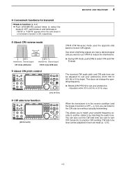
.... u Adjust CW speed with interference, the automatic tuning function may not tune properly, or tune onto an undesired signal. 4-4 tion ON and OFF. • The transceiver automatically tunes the desired sig- D Convenient functions for receive • Preamp (p. 5-9) ➥ Push [P.AMP] several times to adjust the noise reduction level. • Noise reduction...
.... u Adjust CW speed with interference, the automatic tuning function may not tune properly, or tune onto an undesired signal. 4-4 tion ON and OFF. • The transceiver automatically tunes the desired sig- D Convenient functions for receive • Preamp (p. 5-9) ➥ Push [P.AMP] several times to adjust the noise reduction level. • Noise reduction...
Instruction Manual
Page 53
... reduce the interference. ➥ During CW mode, push [CW] to the CW side tone without actually transmitting. D CW side tone function [MONI GAIN] When the transceiver is OFF- p. 6-3) you to match your preference (from 300 to 900 Hz in 25 Hz steps. R mode.
... reduce the interference. ➥ During CW mode, push [CW] to the CW side tone without actually transmitting. D CW side tone function [MONI GAIN] When the transceiver is OFF- p. 6-3) you to match your preference (from 300 to 900 Hz in 25 Hz steps. R mode.
Instruction Manual
Page 56
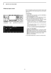
... 1 sec. For your information When an external keypad is incremented each time the contents are set using the keyer send menu. mit, or set the transceiver to [EXT KEYPAD] connector on the rear panel, the programmed contents, M1-M4, can be transmitted without selecting the memory keyer screen. push any function...
... 1 sec. For your information When an external keypad is incremented each time the contents are set using the keyer send menu. mit, or set the transceiver to [EXT KEYPAD] connector on the rear panel, the programmed contents, M1-M4, can be transmitted without selecting the memory keyer screen. push any function...
