Instruction Manual
Page 2
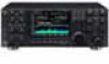
... and operating instructions for making the IC-7800 your IC-7800. With proper care, this product should provide you agree with Icom's philosophy of your time to operate the transceiver. tempting to thank you for the IC-7800. SAVE THIS INSTRUCTION MANUAL. EXPLICIT DEFINITIONS WORD R WARNING CAUTION NOTE DEFINITION Personal injury, fire hazard or electric shock may occur. TRADEMARKS Icom, Icom Inc. center frequency and fix frequency modes, plus mini-scope displays...
... and operating instructions for making the IC-7800 your IC-7800. With proper care, this product should provide you agree with Icom's philosophy of your time to operate the transceiver. tempting to thank you for the IC-7800. SAVE THIS INSTRUCTION MANUAL. EXPLICIT DEFINITIONS WORD R WARNING CAUTION NOTE DEFINITION Personal injury, fire hazard or electric shock may occur. TRADEMARKS Icom, Icom Inc. center frequency and fix frequency modes, plus mini-scope displays...
Instruction Manual
Page 3
... set the transceiver's RF output power to the transceiver. R NEVER let metal, wire or other audio accessories at high volume levels. R NEVER block any cooling vents on the rear panel) OFF and/or disconnect the AC power cable from the magnetic navigation compass to rain, snow or any problems caused by Icom Inc., could void your ears, reduce the volume or discontinue use the transceiver...
... set the transceiver's RF output power to the transceiver. R NEVER let metal, wire or other audio accessories at high volume levels. R NEVER block any cooling vents on the rear panel) OFF and/or disconnect the AC power cable from the magnetic navigation compass to rain, snow or any problems caused by Icom Inc., could void your ears, reduce the volume or discontinue use the transceiver...
Instruction Manual
Page 8
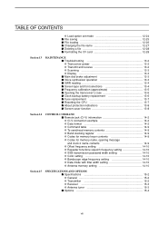
... a frequency from a memo pad 8-7 Section 9 SCANS I Scan types 9-2 I Preparation 9-2 I Voice squelch control function 9-3 I Scan set mode 9-3 I Programmed scan operation 9-4 I ∂F scan operation 9-4 I Fine programmed scan/∂F scan 9-5 I Memory scan operation 9-6 I Select memory scan operation 9-6 I Setting select memory channels 9-7 D Setting in scan screen 9-7 D Setting in memory list screen 9-7 D Erasing the select scan setting 9-7 I Tone scan 9-8 Section 10 ANTENNA TUNER OPERATION I Antenna connection and selection 10-2 I Antenna memory settings 10-3 D Antenna...
... a frequency from a memo pad 8-7 Section 9 SCANS I Scan types 9-2 I Preparation 9-2 I Voice squelch control function 9-3 I Scan set mode 9-3 I Programmed scan operation 9-4 I ∂F scan operation 9-4 I Fine programmed scan/∂F scan 9-5 I Memory scan operation 9-6 I Select memory scan operation 9-6 I Setting select memory channels 9-7 D Setting in scan screen 9-7 D Setting in memory list screen 9-7 D Erasing the select scan setting 9-7 I Tone scan 9-8 Section 10 ANTENNA TUNER OPERATION I Antenna connection and selection 10-2 I Antenna memory settings 10-3 D Antenna...
Instruction Manual
Page 9
... I Formatting the CF card 12-28 Section 13 MAINTENANCE I Troubleshooting 13-2 D Transceiver power 13-2 D Transmit and receive 13-2 D Scanning 13-3 D Display 13-3 I Main dial brake adjustment 13-3 I Voice synthesizer operation 13-3 I SWR reading 13-4 I Screen type and font selections 13-4 I Frequency calibration (approximate 13-5 I Opening the transceiver's case 13-6 I Clock backup battery replacement 13-6 I Fuse replacement 13-7 I Resetting the CPU 13-7 I About protection indications 13-8 I Screen...
... I Formatting the CF card 12-28 Section 13 MAINTENANCE I Troubleshooting 13-2 D Transceiver power 13-2 D Transmit and receive 13-2 D Scanning 13-3 D Display 13-3 I Main dial brake adjustment 13-3 I Voice synthesizer operation 13-3 I SWR reading 13-4 I Screen type and font selections 13-4 I Frequency calibration (approximate 13-5 I Opening the transceiver's case 13-6 I Clock backup battery replacement 13-6 I Fuse replacement 13-7 I Resetting the CPU 13-7 I About protection indications 13-8 I Screen...
Instruction Manual
Page 13
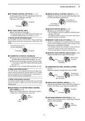
... VOX set mode. (p. 6-2) ✔ What is the break-in function? The VOX function (voice operated transmission) starts transmission without pushing the transmit switch or PTT switch when you stop speaking. ✔ What is the VOX function? Min. 6 wpm Max. 60 wpm !2 BREAK-IN DELAY CONTROL [DELAY] (p. 6-3) Adjusts the transmit-to-receive switching delay time for an Icom microphone Decreases Increases !0 VOX/BREAK-IN SWITCH [VOX/BK-IN] ➥ Push to turn the VOX...
... VOX set mode. (p. 6-2) ✔ What is the break-in function? The VOX function (voice operated transmission) starts transmission without pushing the transmit switch or PTT switch when you stop speaking. ✔ What is the VOX function? Min. 6 wpm Max. 60 wpm !2 BREAK-IN DELAY CONTROL [DELAY] (p. 6-3) Adjusts the transmit-to-receive switching delay time for an Icom microphone Decreases Increases !0 VOX/BREAK-IN SWITCH [VOX/BK-IN] ➥ Push to turn the VOX...
Instruction Manual
Page 16
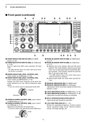
... OPERATION INDICATOR [SPLIT] Lights during split frequency operation. $8 LCD FUNCTION DISPLAY (p. 1-14) Shows the operating frequency, function switch menus, spectrum scope screen, memory channel screen, set mode when pushed for 1 sec. $3 RECEIVE INDICATOR [RX] (for MAIN band) $4 RECEIVE INDICATOR [RX] (for SUB band) Lights green while receiving a signal and when the squelch is in use this control, push the appropriate band's [NR]. p. 5-17) $2 NOISE BLANKER SWITCH [NB] (for MAIN band; for MAIN band; p. 5-18) Lights...
... OPERATION INDICATOR [SPLIT] Lights during split frequency operation. $8 LCD FUNCTION DISPLAY (p. 1-14) Shows the operating frequency, function switch menus, spectrum scope screen, memory channel screen, set mode when pushed for 1 sec. $3 RECEIVE INDICATOR [RX] (for MAIN band) $4 RECEIVE INDICATOR [RX] (for SUB band) Lights green while receiving a signal and when the squelch is in use this control, push the appropriate band's [NR]. p. 5-17) $2 NOISE BLANKER SWITCH [NB] (for MAIN band; for MAIN band; p. 5-18) Lights...
Instruction Manual
Page 23
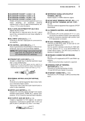
... transceiver. ➥ Used for RTTY/PSK31 decoded signal output. Can be used for remotely control the IC-7800 without the optional CT-17, or for transceive operation with another Icom CI-V transceiver or receiver. #1 RS-232C TERMINAL [RS-232C] (p. 2-5) Connects an RS-232C cable, D-sub 9-pin to connect the IC-7800 to a PC through a LAN (Local Area Network). 1-13 Deactivate the internal electronic keyer in keyer set mode...
... transceiver. ➥ Used for RTTY/PSK31 decoded signal output. Can be used for remotely control the IC-7800 without the optional CT-17, or for transceive operation with another Icom CI-V transceiver or receiver. #1 RS-232C TERMINAL [RS-232C] (p. 2-5) Connects an RS-232C cable, D-sub 9-pin to connect the IC-7800 to a PC through a LAN (Local Area Network). 1-13 Deactivate the internal electronic keyer in keyer set mode...
Instruction Manual
Page 28
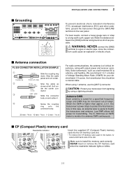
... desired band. When the SWR is of -range. I Antenna connection PL-259 CONNECTOR INSTALLATION EXAMPLE q Coupling ring w e 30 mm 10 mm (soft solder) Slide the coupling ring down. Make sure to protect the final transistors. NEVER insert or remove the CF memory card when the read/write indicator lights or blinks. 2-3 Soft solder the center conductor. Low SWR allows full power...
... desired band. When the SWR is of -range. I Antenna connection PL-259 CONNECTOR INSTALLATION EXAMPLE q Coupling ring w e 30 mm 10 mm (soft solder) Slide the coupling ring down. Make sure to protect the final transistors. NEVER insert or remove the CF memory card when the read/write indicator lights or blinks. 2-3 Soft solder the center conductor. Low SWR allows full power...
Instruction Manual
Page 37
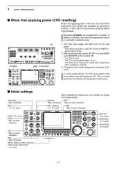
... dark and unstable after resetting, if desired. counter- e Change the set controls as shown in set mode to default values. [POWER] [I/O] [MW] [F-INP•ENT] q Turn the main power ON with [I/O] on the rear panel. • The transceiver power is still OFF and the [POWER] indicator lights orange. Then, reset the transceiver using the following procedure. 3 BASIC OPERATIONS I Initial settings [RF PWR] : Max. Resetting CLEARS all connections required for your...
... dark and unstable after resetting, if desired. counter- e Change the set controls as shown in set mode to default values. [POWER] [I/O] [MW] [F-INP•ENT] q Turn the main power ON with [I/O] on the rear panel. • The transceiver power is still OFF and the [POWER] indicator lights orange. Then, reset the transceiver using the following procedure. 3 BASIC OPERATIONS I Initial settings [RF PWR] : Max. Resetting CLEARS all connections required for your...
Instruction Manual
Page 50
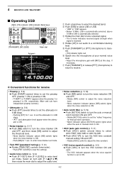
...] for receive • Preamp (p. 5-9) ➥ Push [P.AMP] several times to set to transmit. • [TX] indicator lights red. D Convenient functions for 1 sec. to set mode. above [NR] switch) lights when the noise reduction is ON. • Auto notch filter (p. 5-19) ➥ Push [NOTCH] switch to turn the auto or manual notch function ON and OFF. • Rotate [NOTCH] control to set the "valley" frequency for 1 sec...
...] for receive • Preamp (p. 5-9) ➥ Push [P.AMP] several times to set to transmit. • [TX] indicator lights red. D Convenient functions for 1 sec. to set mode. above [NR] switch) lights when the noise reduction is ON. • Auto notch filter (p. 5-19) ➥ Push [NOTCH] switch to turn the auto or manual notch function ON and OFF. • Rotate [NOTCH] control to set the "valley" frequency for 1 sec...
Instruction Manual
Page 51
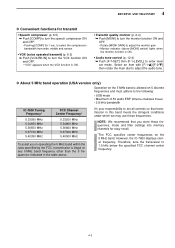
... to set mode. NOTE: We recommend that transmission in this band meets the stringent conditions under which we may use these frequencies, mode and filter settings into memory channels for easy recall. *The FCC specifies center frequencies on any 5 MHz band frequency other than the 5 frequencies indicated in the table above [MONI] switch) lights when the monitor function is ON. • Transmit quality monitor (p. 6-4) ➥ Push [MONI] to turn the...
... to set mode. NOTE: We recommend that transmission in this band meets the stringent conditions under which we may use these frequencies, mode and filter settings into memory channels for easy recall. *The FCC specifies center frequencies on any 5 MHz band frequency other than the 5 frequencies indicated in the table above [MONI] switch) lights when the monitor function is ON. • Transmit quality monitor (p. 6-4) ➥ Push [MONI] to turn the...
Instruction Manual
Page 53
.... The received CW audio pitch and CW side tone can be adjusted in !) to turn OFF break-in level set mode (p. 12-5). 4-5 This allows you want to use the CW side tone (be adjusted to suit your preference (from 300 to another station's by matching the audio tone. CW side tone level can be sure to practice CW sending. This does not change the operating frequency...
.... The received CW audio pitch and CW side tone can be adjusted in !) to turn OFF break-in level set mode (p. 12-5). 4-5 This allows you want to use the CW side tone (be adjusted to suit your preference (from 300 to another station's by matching the audio tone. CW side tone level can be sure to practice CW sending. This does not change the operating frequency...
Instruction Manual
Page 54
... unit main power, if desired. • ON: 2-13.8 V DC input (more than 10 kΩ impedance) • OFF: Less than 2 V DC 4-6 q During CW mode, push [APF/TPF] to turn the audio peak filter ON and OFF. • " APF " appears in CW mode is used for transmit/receive control) *Transverter ON/OFF control signal related to [RELAY] (for the 137 kHz band operation...
... unit main power, if desired. • ON: 2-13.8 V DC input (more than 10 kΩ impedance) • OFF: Less than 2 V DC 4-6 q During CW mode, push [APF/TPF] to turn the audio peak filter ON and OFF. • " APF " appears in CW mode is used for transmit/receive control) *Transverter ON/OFF control signal related to [RELAY] (for the 137 kHz band operation...
Instruction Manual
Page 59
...: Morse code "K" Weight setting: 1:1:3 (default) DOT (fixed*) DASH DASH Weight setting: Adjusted Adjustable range SPACE (fixed*) *SPACE and DOT length can be adjusted with [KEY SPEED] only. • 1:1:2.8 to 1:1:4.5 (in 1 sec. 4 RECEIVE AND TRANSMIT D Keyer set mode [F-1•Y] [F-2•Z][F-4•DEF] [EXIT/SET] Main dial • Keyer set mode screen This set mode is used to set mode. steps can be continued... r Set the desired condition using the repeat timer, this item sets the time between...
...: Morse code "K" Weight setting: 1:1:3 (default) DOT (fixed*) DASH DASH Weight setting: Adjusted Adjustable range SPACE (fixed*) *SPACE and DOT length can be adjusted with [KEY SPEED] only. • 1:1:2.8 to 1:1:4.5 (in 1 sec. 4 RECEIVE AND TRANSMIT D Keyer set mode [F-1•Y] [F-2•Z][F-4•DEF] [EXIT/SET] Main dial • Keyer set mode screen This set mode is used to set mode. steps can be continued... r Set the desired condition using the repeat timer, this item sets the time between...

Instruction Manual
Page 65
... the Channel 1 (RT1) is selected. • Selectable characters (with the main dial); 4 RECEIVE AND TRANSMIT D Editing RTTY memory [123]/[Symbol] [ABC]/[abc] [F-3•DEL] [F-4•SPACE] [F-1•Ω] [F-2•≈] [F-5•Ω≈] [EXIT/SET][F-7•RT1..RT8] • RTTY memory edit screen • Pre-programmed contents CH Name Contents RT1 MYCALLx2 ↵DE ICOM ICOM K↵...
... the Channel 1 (RT1) is selected. • Selectable characters (with the main dial); 4 RECEIVE AND TRANSMIT D Editing RTTY memory [123]/[Symbol] [ABC]/[abc] [F-3•DEL] [F-4•SPACE] [F-1•Ω] [F-2•≈] [F-5•Ω≈] [EXIT/SET][F-7•RT1..RT8] • RTTY memory edit screen • Pre-programmed contents CH Name Contents RT1 MYCALLx2 ↵DE ICOM ICOM K↵...
Instruction Manual
Page 73
...edit screen. • PSK memory contents of the Channel 1 (PT1) is selected. u Repeat steps t and y to set using the memory edit menu. The memory can also be edited from the keyboard. i Push [EXIT/SET] to input the desired characters. r Push [F-5&#...Icom Icom Icom K↵ PT7 RIG&ANT ↵My transceiver is IC-7800 & Antenna is a 3-element triband yagi.↵ PT8 EQUIP. ↵My PSK equipment is internal modulator & demodulator of the IC-7800.↵ The contents of the memory is 70 characters per memory channel. • Programming contents q During PSK mode operation...
...edit screen. • PSK memory contents of the Channel 1 (PT1) is selected. u Repeat steps t and y to set using the memory edit menu. The memory can also be edited from the keyboard. i Push [EXIT/SET] to input the desired characters. r Push [F-5&#...Icom Icom Icom K↵ PT7 RIG&ANT ↵My transceiver is IC-7800 & Antenna is a 3-element triband yagi.↵ PT8 EQUIP. ↵My PSK equipment is internal modulator & demodulator of the IC-7800.↵ The contents of the memory is 70 characters per memory channel. • Programming contents q During PSK mode operation...
Instruction Manual
Page 101
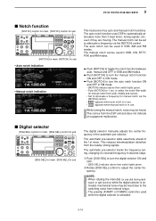
.... • Set to attenuate a frequency via the [NOTCH] control. • " " appears when auto notch is in SSB, AM and FM modes. q Push [DIGI-SEL] to turn the digital selector ON and OFF. • [DIGI-SEL] indicator above their switch lights green. While tuning the manual notch, noise may be used in use . This reduces intermodulation distortion from the DSP unit and...
.... • Set to attenuate a frequency via the [NOTCH] control. • " " appears when auto notch is in SSB, AM and FM modes. q Push [DIGI-SEL] to turn the digital selector ON and OFF. • [DIGI-SEL] indicator above their switch lights green. While tuning the manual notch, noise may be used in use . This reduces intermodulation distortion from the DSP unit and...

Instruction Manual
Page 123
... list screen is convenient for selecting the de- This is impossible. nel readout (below the frequency readout appears if the selected memory channel is useful for transferring programmed contents to VFO. This is a blank channel. q Select VFO mode with [Y]/[Z] in memory mode. • And, set the frequency or operating mode if required. When you have changed the frequency or operating mode in the selected memory channel: • Displayed frequency, mode...
... list screen is convenient for selecting the de- This is impossible. nel readout (below the frequency readout appears if the selected memory channel is useful for transferring programmed contents to VFO. This is a blank channel. q Select VFO mode with [Y]/[Z] in memory mode. • And, set the frequency or operating mode if required. When you have changed the frequency or operating mode in the selected memory channel: • Displayed frequency, mode...
Instruction Manual
Page 168
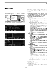
...completed, return to CF card set mode. can be saved into the CF (Compact Flash) memory card for backup. [F-4•EDIT] [F-5•OPTION] [F-7•WIDE]/[F-7•CANCEL] [F-1•DIR/FILE] [F-6•SAVE]/[F-6•OK] [EXIT/SET] Main dial q During set the file name. • ... twice to delete the folder. • Push [F-6•MAKE] for 1 sec. c Push [EXIT/SET] to return to the previous indication. • Saving location z Push [F-1•DIR/FILE] to save screen. SET MODE 12 I File saving Memory channel contents, set menu screen. x Push [ABC], [123] or [Symbol...
...completed, return to CF card set mode. can be saved into the CF (Compact Flash) memory card for backup. [F-4•EDIT] [F-5•OPTION] [F-7•WIDE]/[F-7•CANCEL] [F-1•DIR/FILE] [F-6•SAVE]/[F-6•OK] [EXIT/SET] Main dial q During set the file name. • ... twice to delete the folder. • Push [F-6•MAKE] for 1 sec. c Push [EXIT/SET] to return to the previous indication. • Saving location z Push [F-1•DIR/FILE] to save screen. SET MODE 12 I File saving Memory channel contents, set menu screen. x Push [ABC], [123] or [Symbol...
Instruction Manual
Page 173
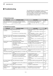
...; Reset the frequency using set the circuit - p. 3-8 or distorted. • PBT function is not connected properly. p. 3-2 • Check for 1 sec. p. 5-12 • Noise blanker is turned ON when receiving a • Push [NB] to a suitable position. when the [POWER] switch • The internal power supply is set too far clockwise or distorted. • Set [MIC] to turn the function ON • Programmed subaudible tone frequency is too low. function OFF. 6-4 Transmit signal...
...; Reset the frequency using set the circuit - p. 3-8 or distorted. • PBT function is not connected properly. p. 3-2 • Check for 1 sec. p. 5-12 • Noise blanker is turned ON when receiving a • Push [NB] to a suitable position. when the [POWER] switch • The internal power supply is set too far clockwise or distorted. • Set [MIC] to turn the function ON • Programmed subaudible tone frequency is too low. function OFF. 6-4 Transmit signal...


